CN202088643U - Silk screen printing jig - Google Patents
Silk screen printing jig Download PDFInfo
- Publication number
- CN202088643U CN202088643U CN2011201361475U CN201120136147U CN202088643U CN 202088643 U CN202088643 U CN 202088643U CN 2011201361475 U CN2011201361475 U CN 2011201361475U CN 201120136147 U CN201120136147 U CN 201120136147U CN 202088643 U CN202088643 U CN 202088643U
- Authority
- CN
- China
- Prior art keywords
- fixed
- web plate
- silk
- rotating shaft
- balancing weight
- Prior art date
- Legal status (The legal status is an assumption and is not a legal conclusion. Google has not performed a legal analysis and makes no representation as to the accuracy of the status listed.)
- Expired - Fee Related
Links
Images
Abstract
The utility model relates to a silk screen printing jig, which comprises two fixing pillars, a balancing weight, a screen board fixing bracket and a rotating shaft, wherein two shaft sleeves are fixed on the two fixing pillars respectively through tighten screws; the rotating shaft is connected between the two shaft sleeves; an extension rod is fixedly connected on one side of the middle part of the rotating shaft, and the other side is connected with the screen board fixing bracket; a bayonet is arranged on the screen board fixing bracket, and the screen board is inserted and fixed into the bayonet; and the balancing weight is fixed on the extension rod. The silk screen printing jig is characterized in that a fixing frame is included, and the fixing frame is connected fixedly with the fixing pillars. Due to the adoption of the silk screen printing jig, the stability is greatly improved, the convenient and time-saving and labor-saving regulation is achieved, the labor intensity of the operators is reduced, the production efficiency is enhanced, the rejection rate of the screen board is reduced, and the cost is saved.
Description
Technical field
The utility model relates to a kind of silk-screen tool, belongs to the screen printing device technical field.
Background technology
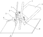
Fig. 1 is the structural representation of traditional silk-screen tool.
As shown in Figure 1: the silk-screen tool comprises two fixed legs 1, balancing weight 2, a web plate fixed mount 7 and a rotating shaft, wherein, be fixed with two axle sleeves 5 by screwing screw respectively on two fixed legs 1, be connected with rotating shaft 4 between two axle sleeves 5, centre position one side of rotating shaft 4 is fixedly connected with an extension rod 6, opposite side then is connected with web plate fixed mount 7, above-mentioned web plate fixed mount 7 is provided with a bayonet socket 8, described web plate 3 is inserted in the bayonet socket 8 and fixes, and above-mentioned balancing weight 2 then is fixed on the extension rod 6.
Above-mentioned balancing weight 2, rotating shaft 4 and the web plate 3 that is connected on the web plate fixed mount 7 form lever construction together, wherein, rotating shaft 4 forms the pivot point of lever, wherein the weight of balancing weight 2 is greater than web plate 3, under untapped state, because the gravity effect of balancing weight 2, balancing weight 2 is downward-sloping, be its extension rod 6 against on the ground, the web plate 3 of the other end then is outstanding high.When needs carry out the silk-screen operation, operating personnel are depressed into operating position with web plate 3, carry out the silk-screen operation, when the silk-screen operation is finished, operating personnel unclamp web plate, under the effect of balancing weight 2, web plate 3 is got back to original position, in this tool, because the lever weight between balancing weight 2 and the web plate 3 differs smaller, therefore, operating personnel do not need can realize with very big power in operation web plate 3.
Above-mentioned silk-screen tool, because it adopts two fixed legs 1 to fix, therefore its stability is bad, the situation of overturning takes place easily, especially when the axle sleeve of regulating on the fixed leg 15, make rotating shaft 4 raise, after soon web plate 3 highly raises, the stability of whole tool will be poorer, in addition, because after needing the product of silk-screen to be placed on web plate 3 bottoms,, need regulate the direction of web plate 3 if the position places is not very accurately under the situation, and the web plate of above-mentioned silk-screen tool is when putting down, if find that the position of itself and product is inconsistent, then need iron hammer to knock the adjusting that product carries out product space, this kind regulative mode is not only wasted time and energy, and, because web plate and product are very approaching, when product mobile, be easy to the scratch web plate and the situation of cost of idleness.
Summary of the invention
The purpose of this utility model is to provide a kind of good stability, and convenient, the easy silk-screen tool of web plate position adjustments.
The utility model is achieved through the following technical solutions:
A kind of silk-screen tool, comprise two fixed legs, balancing weight, a web plate fixed mount and a rotating shaft, wherein, be fixed with two axle sleeves by screwing screw respectively on two fixed legs, be connected with rotating shaft between two axle sleeves, centre position one side of rotating shaft is fixedly connected with an extension rod, opposite side then is connected with the web plate fixed mount, above-mentioned web plate fixed mount is provided with a bayonet socket, described web plate is inserted in the bayonet socket and fixes, and above-mentioned balancing weight then is fixed on the extension rod, it is characterized in that, also comprise a fixed frame, described fixed frame and fixed leg are connected and fixed.
Above-mentioned fixed frame comprises connecting plate and base, and wherein connecting plate is arranged on the outside of fixed leg, and be arranged in parallel with fixed leg, and the fixed leg connection corresponding with it of its upper end, and base is fixedlyed connected with the bottom of connecting plate and fixed leg.
The top of above-mentioned base also is provided with a product standing groove, and the edge of product standing groove is provided with a plurality of screws that screw.
The cross section of the bayonet socket of above-mentioned web plate fixed mount is a u type structure, and the u type limit of a side is provided with and screws screw.
The beneficial effects of the utility model are: the utility model is by adding fixed frame, make center of gravity of the present utility model on the base of fixed frame, because base is one to have the plate body on big plane, therefore, its area that contacts with ground is far longer than the area that original fixed leg contacts with ground, has therefore increased stability of the present utility model greatly; In addition, because base is provided with the product standing groove, and its edge is provided with a plurality of screws that screw, after product is put into the product standing groove, can be by regulating the position that screw is regulated product that screws on the product standing groove edge, can remove to beat product with hammer again product is regulated, make that like this adjusting is very convenient, and time saving and energy saving, reduced labor intensity of operating personnel, improve production efficiency, reduced the scrappage of web plate, saved cost.
Description of drawings
Fig. 1 is the structural representation of traditional silk-screen tool;
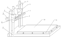
Fig. 2 is the structural representation of the utility model one embodiment.
The implication of main Reference numeral is among the figure:
1, fixed leg 2, balancing weight 3, web plate 4, rotating shaft
5, axle sleeve 6, extension rod 7, web plate fixed mount 8, bayonet socket
9, connecting plate 10, base 11, product standing groove 12, product.
The specific embodiment
Describe the specific embodiment of the present utility model in detail below in conjunction with the drawings and specific embodiments:
Fig. 2 is the structural representation of the utility model one embodiment.
As shown in Figure 2: a kind of silk-screen tool, comprise two fixed legs 1, a balancing weight 2, an one web plate fixed mount 7 and a rotating shaft 4, wherein, be fixed with two axle sleeves 5 by screwing screw respectively on two fixed legs 1, be connected with rotating shaft 4 between two axle sleeves 5, centre position one side of rotating shaft 4 is fixedly connected with an extension rod 6, opposite side then is connected with web plate fixed mount 7, above-mentioned web plate fixed mount 7 is provided with a bayonet socket 8, described web plate 3 is inserted in the bayonet socket 8 and fixes, and above-mentioned balancing weight 2 then is fixed on the extension rod 6, in addition, the utility model also comprises a fixed frame, and described fixed frame and fixed leg 1 are connected and fixed.
In the present embodiment, fixed frame comprises connecting plate 9 and base 10, wherein connecting plate 9 is arranged on the outside of fixed leg 1, and be arranged in parallel with fixed leg 1, and its upper end fixed leg 1 corresponding with it connects, base 10 is fixedlyed connected with the bottom of fixed leg 1 with connecting plate 9, and also be provided with product standing groove 11 on the base 10, the edge of product standing groove 11 is provided with a plurality of screws that screw, in the present embodiment, former and later two edges of product standing groove 11 are respectively arranged with three and screw screw, about two edges be respectively arranged with two and screw screw, and evenly be provided with, carry out balance and screw being arranged on products 12 in the product standing groove 11 guaranteeing, certainly, screw screw and be not restricted to the number that each edge is provided with, it can carry out number as required and limit for the stress balance of product.
In addition, the cross section of the bayonet socket 8 of above-mentioned web plate fixed mount 7 is a u type structure, and the u type limit of a side is provided with and screws screw, in the present embodiment, in opening u type structure to the right, it screws on the u type limit that screw is arranged on upside, and it is screwed down fixedly web plate 3, and in the present embodiment, the described screw that screws that is used for fixing web plate 3 is provided with three, certainly, in actual production process, can select the number that screws screw as required.
Above-mentioned balancing weight 2, rotating shaft 4 and the web plate 3 that is connected on the web plate fixed mount 7 form lever construction together, wherein, rotating shaft 4 forms the pivot point of lever, wherein the weight of balancing weight 2 is greater than web plate 3, under untapped state, because the gravity effect of balancing weight 2, balancing weight 2 is downward-sloping, be its extension rod 6 on ground, the web plate 3 of the other end then is outstanding high.When needs carry out the silk-screen operation, operating personnel are depressed into operating position with web plate 3, carry out the silk-screen operation, when the silk-screen operation is finished, operating personnel unclamp web plate 3, under the effect of balancing weight 2, web plate 3 is got back to original position, in this tool, because the lever weight between balancing weight 2 and the web plate 3 differs smaller, therefore, operating personnel do not need can realize with very big power in operation web plate 3.
In addition, if desired the position of product 12 is regulated, promptly come product 12 is carried out position adjustments, after regulating, can carry out the silk-screen operation to the greatest extent by the screw that screws of regulating product standing groove edge on the base 10.
The utility model is by adding fixed frame, make center of gravity of the present utility model on the base 10 of fixed frame, because base 10 is one to have the plate body on big plane, therefore, its area that contacts with ground is far longer than the area that original fixed leg 1 contacts with ground, has therefore increased stability of the present utility model greatly; In addition, because the top of base 10 is provided with product standing groove 11, the edge of product standing groove 11 is provided with and screws screw, therefore, after product is placed into product standing groove 11, can be by regulating the position that screw is regulated product 12 that screws at product standing groove 11 edges, can remove to beat 12 pairs of products 12 of product with hammer again regulates, make that like this adjusting is very convenient, and time saving and energy saving, reduced labor intensity of operating personnel, improved production efficiency, reduce the scrappage of web plate, saved cost.
The foregoing description does not limit the utility model in any form, and all employings are equal to the technical scheme that mode obtained of replacement or equivalent transformation, all drop in the protection domain of the present utility model.
Claims (5)
1. silk-screen tool, comprise two fixed legs, balancing weight, a web plate fixed mount and a rotating shaft, wherein, be fixed with two axle sleeves by screwing screw respectively on two fixed legs, be connected with rotating shaft between two axle sleeves, centre position one side of rotating shaft is fixedly connected with an extension rod, opposite side then is connected with the web plate fixed mount, above-mentioned web plate fixed mount is provided with a bayonet socket, described web plate is inserted in the bayonet socket and fixes, and above-mentioned balancing weight then is fixed on the extension rod, it is characterized in that, also comprise a fixed frame, described fixed frame and fixed leg are connected and fixed.
2. a kind of silk-screen tool according to claim 1, it is characterized in that, described fixed frame comprises connecting plate and base, wherein connecting plate is arranged on the outside of fixed leg, and be arranged in parallel with fixed leg, and its upper end fixed leg corresponding with it connects, and base is fixedlyed connected with the bottom of connecting plate and fixed leg.
3. a kind of silk-screen tool according to claim 2 is characterized in that the top of described base also is provided with a product standing groove.
4. a kind of silk-screen tool according to claim 3 is characterized in that the edge of described product standing groove is provided with a plurality of screws that screw.
5. a kind of silk-screen tool according to claim 1 is characterized in that, the cross section of the bayonet socket of described web plate fixed mount is a u type structure, and the u type limit of a side is provided with and screws screw.
Priority Applications (1)
| Application Number | Priority Date | Filing Date | Title |
|---|---|---|---|
| CN2011201361475U CN202088643U (en) | 2011-05-03 | 2011-05-03 | Silk screen printing jig |
Applications Claiming Priority (1)
| Application Number | Priority Date | Filing Date | Title |
|---|---|---|---|
| CN2011201361475U CN202088643U (en) | 2011-05-03 | 2011-05-03 | Silk screen printing jig |
Publications (1)
| Publication Number | Publication Date |
|---|---|
| CN202088643U true CN202088643U (en) | 2011-12-28 |
Family
ID=45363732
Family Applications (1)
| Application Number | Title | Priority Date | Filing Date |
|---|---|---|---|
| CN2011201361475U Expired - Fee Related CN202088643U (en) | 2011-05-03 | 2011-05-03 | Silk screen printing jig |
Country Status (1)
| Country | Link |
|---|---|
| CN (1) | CN202088643U (en) |
Cited By (1)
| Publication number | Priority date | Publication date | Assignee | Title |
|---|---|---|---|---|
| CN102241184A (en) * | 2011-05-03 | 2011-11-16 | 兴威电脑(昆山)有限公司 | Screen print jig |
-
2011
- 2011-05-03 CN CN2011201361475U patent/CN202088643U/en not_active Expired - Fee Related
Cited By (1)
| Publication number | Priority date | Publication date | Assignee | Title |
|---|---|---|---|---|
| CN102241184A (en) * | 2011-05-03 | 2011-11-16 | 兴威电脑(昆山)有限公司 | Screen print jig |
Similar Documents
| Publication | Publication Date | Title |
|---|---|---|
| CN201872154U (en) | Variable-height slide rail regulating platform | |
| CN202668522U (en) | Height-variable slide rail installing and adjusting platform | |
| CN204277870U (en) | A kind of distribution box assembling fixture | |
| CN203433792U (en) | Simple musical instrument bracket | |
| CN102241184A (en) | Screen print jig | |
| CN205159883U (en) | Portable high voltage isolator examines and repair work platform | |
| CN202088643U (en) | Silk screen printing jig | |
| CN204277474U (en) | Liftable type lathe | |
| CN203672471U (en) | Independent damping type balance platform | |
| CN205104359U (en) | Three -dimensional quick positioning and fixing device of iron core that rolls up of triangle -shaped | |
| CN204338443U (en) | A kind of Universal base for TPU point glue location | |
| CN203356541U (en) | Sand core receiving manipulator | |
| CN204295741U (en) | A kind of photovoltaic module splitting machine | |
| CN204366552U (en) | A kind of fixture based on Internet of Things | |
| CN203843745U (en) | Assembling and disassembling fixture for electric generator of loader | |
| CN201684865U (en) | Bending and reshaping fixture for pin of optical device | |
| CN202655686U (en) | Suspended drilling adjusting bracket | |
| CN105202322A (en) | Multi-angle fixing rack | |
| CN202174396U (en) | Pressure balancing stand | |
| CN205793870U (en) | A kind of Simple adjustable tool paying circuit board for fixing lock | |
| CN204633683U (en) | A kind of novel portable solar photovoltaic bracket | |
| CN205092813U (en) | Assembly of solar cell panel frame | |
| CN204349724U (en) | Generator stator rotor combination assembly tooling | |
| CN204324339U (en) | A kind of clamping mechanism on solar cell board assembly line | |
| CN203622590U (en) | Bamboo knocking machine structure |
Legal Events
| Date | Code | Title | Description |
|---|---|---|---|
| C14 | Grant of patent or utility model | ||
| GR01 | Patent grant | ||
| CF01 | Termination of patent right due to non-payment of annual fee |
Granted publication date: 20111228 Termination date: 20160503 |
|
| CF01 | Termination of patent right due to non-payment of annual fee |