CN202084814U - Crowbar for switch cabinet energy storage spring assembling and disassembling tool - Google Patents
Crowbar for switch cabinet energy storage spring assembling and disassembling tool Download PDFInfo
- Publication number
- CN202084814U CN202084814U CN2011202177493U CN201120217749U CN202084814U CN 202084814 U CN202084814 U CN 202084814U CN 2011202177493 U CN2011202177493 U CN 2011202177493U CN 201120217749 U CN201120217749 U CN 201120217749U CN 202084814 U CN202084814 U CN 202084814U
- Authority
- CN
- China
- Prior art keywords
- crowbar
- connecting plate
- energy storage
- switch cabinet
- ripping bar
- Prior art date
- Legal status (The legal status is an assumption and is not a legal conclusion. Google has not performed a legal analysis and makes no representation as to the accuracy of the status listed.)
- Expired - Lifetime
Links
Images

Landscapes
- Working Measures On Existing Buildindgs (AREA)
Abstract
本实用新型公开了一种开关柜储能弹簧拆装工具用的撬棍,包括撬杆和撬杆一端的撬头,所述撬头向撬杆一侧弯曲,撬杆的另一侧设有一连接板,所述连接板的一边沿与撬杆固定,在连接板上开有数个通孔。本实用新型加工更加方便,且能够根据实际情况调整撬棍,更加灵活,并且操作也更加方便。
The utility model discloses a crowbar for disassembling and assembling a switch cabinet energy storage spring, which comprises a crowbar and a crowbar at one end of the crowbar. The crowbar is bent toward one side of the crowbar, and a A connecting plate, one edge of the connecting plate is fixed with a pry bar, and several through holes are opened on the connecting plate. The utility model has more convenient processing, and can adjust the crowbar according to the actual situation, is more flexible, and the operation is also more convenient.
Description
技术领域 technical field
本实用新型涉及一种开关柜储能弹簧拆装工具上的部件,尤其涉及一种开关柜储能弹簧拆装工具用的撬棍。 The utility model relates to a component on a switch cabinet energy storage spring disassembly tool, in particular to a crowbar used for a switch cabinet energy storage spring disassembly tool.
背景技术 Background technique
在变电设备检修中,都会涉及到弹簧操作机构的检修,要拆装弹簧非常的麻烦,尤其是开关柜储能弹簧,因此有人设计了一种拆装工具,包括连接杆,在连接杆上端设置夹板,通过夹板将该工具固定在开关柜支架或外壳上,然后在连接杆下端转动连接一撬棍,通过撬棍将弹簧拆卸或安装,目前的撬棍在安装时采用的是在连接杆下端开设一凹槽,然后通过轴将撬棍安装与该凹槽内,使的撬棍能够绕轴转动。但是这样的撬棍安装到连接杆上时需要在撬棍上开一通孔,加工非常麻烦,安装好后,无法调整其位置,对于一些设备使用就不方便,不够灵活。 In the maintenance of substation equipment, the maintenance of the spring operating mechanism will be involved. It is very troublesome to disassemble and assemble the spring, especially the energy storage spring of the switch cabinet. Therefore, someone has designed a disassembly tool, including the connecting rod. Set the splint, fix the tool on the switch cabinet bracket or shell through the splint, and then rotate and connect a crowbar at the lower end of the connecting rod, and disassemble or install the spring through the crowbar. The current crowbar is installed on the connecting rod A groove is opened at the lower end, and then the crowbar is installed in the groove through the shaft, so that the crowbar can rotate around the shaft. But when such crowbar is installed on the connecting rod, a through hole needs to be opened on the crowbar, and the processing is very troublesome. After installation, its position cannot be adjusted, which is inconvenient and not flexible enough for some equipment.
实用新型内容 Utility model content
针对现有技术存在的上述不足,本实用新型的目的就在于提供一种开关柜储能弹簧拆装工具用的撬棍,加工和使用更方便,更加灵活。 In view of the above-mentioned deficiencies in the prior art, the purpose of this utility model is to provide a crowbar for dismounting and assembling the switchgear energy storage spring, which is more convenient and flexible to process and use.
为了实现上述目的,本实用新型采用的技术方案是这样的:开关柜储能弹簧拆装工具用的撬棍,包括撬杆和撬杆一端的撬头,所述撬头向撬杆一侧弯曲,撬杆的另一侧设有一连接板,所述连接板的一边沿与撬杆固定,在连接板上开有数个通孔。 In order to achieve the above object, the technical solution adopted by the utility model is as follows: the crowbar used for the switch cabinet energy storage spring dismounting tool includes a crowbar and a crowbar at one end of the crowbar, and the crowbar is bent to one side of the crowbar , The other side of the pry bar is provided with a connecting plate, one edge of the connecting plate is fixed with the pry bar, and several through holes are opened on the connecting plate.
进一步地,所述通孔沿撬杆的长度方向均匀分布,结构更加合理。 Further, the through holes are evenly distributed along the length direction of the pry bar, and the structure is more reasonable.
所述连接板为长方形板,其一长边沿与撬杆相连。 The connecting plate is a rectangular plate, one long edge of which is connected with the pry bar.
与现有技术相比,本实用新型的优点在于:加工更加方便,且能够根据实际情况调整撬棍,更加灵活,并且操作也更加方便。 Compared with the prior art, the utility model has the advantages that the processing is more convenient, the crowbar can be adjusted according to the actual situation, the utility model is more flexible, and the operation is more convenient.
附图说明 Description of drawings
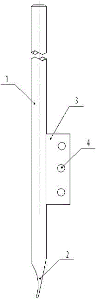
图1为本实用新型的主视图; Fig. 1 is the front view of the utility model;
图2为图1的侧视图。 FIG. 2 is a side view of FIG. 1 .
具体实施方式 Detailed ways
下面将结合附图对本实用新型作进一步说明。 The utility model will be further described below in conjunction with accompanying drawing.
实施例:参见图1、图2,本实用新型一种开关柜储能弹簧拆装工具用的撬棍,包括撬杆1和撬杆1一端的撬头2,所述撬头2向撬杆1一侧弯曲,撬杆1的另一侧设有一连接板3,所述连接板3的一边沿与撬杆1固定,作为优选,该连接板3为长方形板,其一长边沿与撬杆1相连,该连接板3与撬杆1可通过焊接的方式固定在一起,在连接板3上开有数个通孔4,所述通孔4沿撬杆2的长度方向均匀分布,撬头2前端扁平部铣有一槽口,结构更加合理,更加实用。这样通过轴将连接板3安装于连接杆下端的凹槽内更加方便,且在板上开孔相对于直接在撬杆1上开孔也更方便,使用过程中能够根据实际情况调整撬棍,更加灵活。 Embodiment: Referring to Fig. 1 and Fig. 2, the utility model is a crowbar for disassembling and assembling a switch cabinet energy storage spring, including a crowbar 1 and a crowbar 2 at one end of the crowbar 1, and the crowbar 2 is directed toward the crowbar. One side of 1 is bent, and the other side of the pry bar 1 is provided with a connecting plate 3, and one edge of the connecting plate 3 is fixed with the pry bar 1. As preferably, the connecting plate 3 is a rectangular plate, and one long edge thereof is connected with the pry bar. 1 connected, the connection plate 3 and the pry bar 1 can be fixed together by welding, and several through holes 4 are opened on the connection plate 3, and the through holes 4 are evenly distributed along the length direction of the pry bar 2, and the pry head 2 A notch is milled on the flat part of the front end, which makes the structure more reasonable and practical. In this way, it is more convenient to install the connecting plate 3 in the groove at the lower end of the connecting rod through the shaft, and it is also more convenient to open holes on the plate than directly opening holes on the crowbar 1, and the crowbar can be adjusted according to the actual situation during use. more flexible.
在实际使用过程中,可以采用螺栓代替轴,这样操作更方便,更快捷。 In actual use, bolts can be used instead of shafts, which makes the operation more convenient and faster.
Claims (3)
Priority Applications (1)
| Application Number | Priority Date | Filing Date | Title |
|---|---|---|---|
| CN2011202177493U CN202084814U (en) | 2011-06-24 | 2011-06-24 | Crowbar for switch cabinet energy storage spring assembling and disassembling tool |
Applications Claiming Priority (1)
| Application Number | Priority Date | Filing Date | Title |
|---|---|---|---|
| CN2011202177493U CN202084814U (en) | 2011-06-24 | 2011-06-24 | Crowbar for switch cabinet energy storage spring assembling and disassembling tool |
Publications (1)
| Publication Number | Publication Date |
|---|---|
| CN202084814U true CN202084814U (en) | 2011-12-21 |
Family
ID=45345431
Family Applications (1)
| Application Number | Title | Priority Date | Filing Date |
|---|---|---|---|
| CN2011202177493U Expired - Lifetime CN202084814U (en) | 2011-06-24 | 2011-06-24 | Crowbar for switch cabinet energy storage spring assembling and disassembling tool |
Country Status (1)
| Country | Link |
|---|---|
| CN (1) | CN202084814U (en) |
Cited By (1)
| Publication number | Priority date | Publication date | Assignee | Title |
|---|---|---|---|---|
| CN104319135A (en) * | 2014-09-26 | 2015-01-28 | 国网安徽省电力公司阜阳供电公司 | Energy storing spring dismounting device of vacuum circuit breaker mechanism |
-
2011
- 2011-06-24 CN CN2011202177493U patent/CN202084814U/en not_active Expired - Lifetime
Cited By (1)
| Publication number | Priority date | Publication date | Assignee | Title |
|---|---|---|---|---|
| CN104319135A (en) * | 2014-09-26 | 2015-01-28 | 国网安徽省电力公司阜阳供电公司 | Energy storing spring dismounting device of vacuum circuit breaker mechanism |
Similar Documents
| Publication | Publication Date | Title |
|---|---|---|
| CN202556045U (en) | Disassembling tool for isolation switch connection rod cylindrical pin | |
| CN203835025U (en) | Linear rod cross arm capable of being conveniently connected | |
| CN102779672B (en) | Tool special for assembling and disassembling contact finger of disconnecting switch | |
| CN201079945Y (en) | Puller | |
| CN202084813U (en) | Assembling and disassembling tool for switch cabinet energy-storage spring | |
| CN102649226A (en) | Detaching tool of cylindrical pin of connecting rod of disconnecting switch | |
| CN203109899U (en) | Insulation tool for installing bird repellent without power failure | |
| CN203752092U (en) | Spring disassembling mechanism | |
| CN202513517U (en) | Bracket arm hoop | |
| CN201332228Y (en) | Special tool for disassembling crank arm copper sleeves arranged at the base of oil-minimum breaker | |
| CN204230770U (en) | A kind of bird-scaring unit erecting tools | |
| CN201444459U (en) | Stable Connection Mechanism Device for High Voltage Switch Operation Knife Switch and Auxiliary Switch | |
| CN203367866U (en) | Live-line assembling/disassembling cotter pin device | |
| CN201815503U (en) | Reversible spray valve plate support of color sorting machine | |
| CN204066938U (en) | A kind of instrument panel structure of wind power generation combined type transformer low pressure storehouse | |
| CN204597333U (en) | A kind of low-voltage drawer type power distributing cabinet drawer is with exempting to weld hinge | |
| CN204517170U (en) | Outdoor vacuum switch insulating support | |
| CN201594703U (en) | 35kV switchgear current transformer installation trailer | |
| CN203406022U (en) | Transformer substation isolating disconnecting link nameplate installing support | |
| CN203992704U (en) | A kind of reflow machine | |
| CN2850079Y (en) | Anti-drop off power distributor | |
| CN203822792U (en) | Novel split pin | |
| CN202684813U (en) | Electric wrench connector | |
| CN214125710U (en) | Door type panel and electrical cabinet | |
| CN201539126U (en) | Repair tower valve installation trimmer |
Legal Events
| Date | Code | Title | Description |
|---|---|---|---|
| C14 | Grant of patent or utility model | ||
| GR01 | Patent grant | ||
| ASS | Succession or assignment of patent right |
Owner name: STATE GRID CORPORATION OF CHINA Effective date: 20121218 |
|
| C41 | Transfer of patent application or patent right or utility model | ||
| TR01 | Transfer of patent right |
Effective date of registration: 20121218 Address after: 400053 Chongqing Jiulongpo Huangjueping power five Village No. 50 Patentee after: Chongqing Power Education & Training Center Patentee after: State Grid Corporation of China Address before: 400053 Chongqing Jiulongpo Huangjueping power five Village No. 50 Patentee before: Chongqing Power Education & Training Center |
|
| CX01 | Expiry of patent term | ||
| CX01 | Expiry of patent term |
Granted publication date: 20111221 |