CN202073806U - Heat radiation fan - Google Patents
Heat radiation fan Download PDFInfo
- Publication number
- CN202073806U CN202073806U CN201120145895XU CN201120145895U CN202073806U CN 202073806 U CN202073806 U CN 202073806U CN 201120145895X U CN201120145895X U CN 201120145895XU CN 201120145895 U CN201120145895 U CN 201120145895U CN 202073806 U CN202073806 U CN 202073806U
- Authority
- CN
- China
- Prior art keywords
- impeller
- auxiliary axis
- heat
- dissipating fan
- cover plate
- Prior art date
- Legal status (The legal status is an assumption and is not a legal conclusion. Google has not performed a legal analysis and makes no representation as to the accuracy of the status listed.)
- Expired - Lifetime
Links
- 230000005855 radiation Effects 0.000 title abstract 6
- 241000883990 Flabellum Species 0.000 claims description 48
- NJPPVKZQTLUDBO-UHFFFAOYSA-N novaluron Chemical compound C1=C(Cl)C(OC(F)(F)C(OC(F)(F)F)F)=CC=C1NC(=O)NC(=O)C1=C(F)C=CC=C1F NJPPVKZQTLUDBO-UHFFFAOYSA-N 0.000 claims description 37
- 230000000694 effects Effects 0.000 abstract description 19
- 238000004519 manufacturing process Methods 0.000 abstract description 5
- 230000017525 heat dissipation Effects 0.000 abstract 2
- 238000006073 displacement reaction Methods 0.000 description 9
- 230000000630 rising effect Effects 0.000 description 9
- NHDHVHZZCFYRSB-UHFFFAOYSA-N pyriproxyfen Chemical compound C=1C=CC=NC=1OC(C)COC(C=C1)=CC=C1OC1=CC=CC=C1 NHDHVHZZCFYRSB-UHFFFAOYSA-N 0.000 description 5
- 241001075561 Fioria Species 0.000 description 2
- 239000000463 material Substances 0.000 description 2
- 239000007769 metal material Substances 0.000 description 2
- 230000000153 supplemental effect Effects 0.000 description 2
- 238000005516 engineering process Methods 0.000 description 1
- 239000012530 fluid Substances 0.000 description 1
- 230000006698 induction Effects 0.000 description 1
- 230000005389 magnetism Effects 0.000 description 1
- 238000000034 method Methods 0.000 description 1
Images


Classifications
-
- F—MECHANICAL ENGINEERING; LIGHTING; HEATING; WEAPONS; BLASTING
- F04—POSITIVE - DISPLACEMENT MACHINES FOR LIQUIDS; PUMPS FOR LIQUIDS OR ELASTIC FLUIDS
- F04D—NON-POSITIVE-DISPLACEMENT PUMPS
- F04D25/00—Pumping installations or systems
- F04D25/02—Units comprising pumps and their driving means
- F04D25/06—Units comprising pumps and their driving means the pump being electrically driven
- F04D25/0606—Units comprising pumps and their driving means the pump being electrically driven the electric motor being specially adapted for integration in the pump
- F04D25/0613—Units comprising pumps and their driving means the pump being electrically driven the electric motor being specially adapted for integration in the pump the electric motor being of the inside-out type, i.e. the rotor is arranged radially outside a central stator
- F04D25/062—Details of the bearings
-
- F—MECHANICAL ENGINEERING; LIGHTING; HEATING; WEAPONS; BLASTING
- F04—POSITIVE - DISPLACEMENT MACHINES FOR LIQUIDS; PUMPS FOR LIQUIDS OR ELASTIC FLUIDS
- F04D—NON-POSITIVE-DISPLACEMENT PUMPS
- F04D29/00—Details, component parts, or accessories
- F04D29/04—Shafts or bearings, or assemblies thereof
-
- F—MECHANICAL ENGINEERING; LIGHTING; HEATING; WEAPONS; BLASTING
- F04—POSITIVE - DISPLACEMENT MACHINES FOR LIQUIDS; PUMPS FOR LIQUIDS OR ELASTIC FLUIDS
- F04D—NON-POSITIVE-DISPLACEMENT PUMPS
- F04D17/00—Radial-flow pumps, e.g. centrifugal pumps; Helico-centrifugal pumps
- F04D17/02—Radial-flow pumps, e.g. centrifugal pumps; Helico-centrifugal pumps having non-centrifugal stages, e.g. centripetal
- F04D17/04—Radial-flow pumps, e.g. centrifugal pumps; Helico-centrifugal pumps having non-centrifugal stages, e.g. centripetal of transverse-flow type
-
- F—MECHANICAL ENGINEERING; LIGHTING; HEATING; WEAPONS; BLASTING
- F04—POSITIVE - DISPLACEMENT MACHINES FOR LIQUIDS; PUMPS FOR LIQUIDS OR ELASTIC FLUIDS
- F04D—NON-POSITIVE-DISPLACEMENT PUMPS
- F04D17/00—Radial-flow pumps, e.g. centrifugal pumps; Helico-centrifugal pumps
- F04D17/08—Centrifugal pumps
- F04D17/16—Centrifugal pumps for displacing without appreciable compression
-
- F—MECHANICAL ENGINEERING; LIGHTING; HEATING; WEAPONS; BLASTING
- F04—POSITIVE - DISPLACEMENT MACHINES FOR LIQUIDS; PUMPS FOR LIQUIDS OR ELASTIC FLUIDS
- F04D—NON-POSITIVE-DISPLACEMENT PUMPS
- F04D25/00—Pumping installations or systems
- F04D25/02—Units comprising pumps and their driving means
-
- F—MECHANICAL ENGINEERING; LIGHTING; HEATING; WEAPONS; BLASTING
- F04—POSITIVE - DISPLACEMENT MACHINES FOR LIQUIDS; PUMPS FOR LIQUIDS OR ELASTIC FLUIDS
- F04D—NON-POSITIVE-DISPLACEMENT PUMPS
- F04D27/00—Control, e.g. regulation, of pumps, pumping installations or pumping systems specially adapted for elastic fluids
- F04D27/008—Stop safety or alarm devices, e.g. stop-and-go control; Disposition of check-valves
-
- F—MECHANICAL ENGINEERING; LIGHTING; HEATING; WEAPONS; BLASTING
- F04—POSITIVE - DISPLACEMENT MACHINES FOR LIQUIDS; PUMPS FOR LIQUIDS OR ELASTIC FLUIDS
- F04D—NON-POSITIVE-DISPLACEMENT PUMPS
- F04D29/00—Details, component parts, or accessories
- F04D29/05—Shafts or bearings, or assemblies thereof, specially adapted for elastic fluid pumps
- F04D29/051—Axial thrust balancing
-
- F—MECHANICAL ENGINEERING; LIGHTING; HEATING; WEAPONS; BLASTING
- F04—POSITIVE - DISPLACEMENT MACHINES FOR LIQUIDS; PUMPS FOR LIQUIDS OR ELASTIC FLUIDS
- F04D—NON-POSITIVE-DISPLACEMENT PUMPS
- F04D29/00—Details, component parts, or accessories
- F04D29/05—Shafts or bearings, or assemblies thereof, specially adapted for elastic fluid pumps
- F04D29/052—Axially shiftable rotors
-
- H—ELECTRICITY
- H02—GENERATION; CONVERSION OR DISTRIBUTION OF ELECTRIC POWER
- H02K—DYNAMO-ELECTRIC MACHINES
- H02K7/00—Arrangements for handling mechanical energy structurally associated with dynamo-electric machines, e.g. structural association with mechanical driving motors or auxiliary dynamo-electric machines
- H02K7/14—Structural association with mechanical loads, e.g. with hand-held machine tools or fans
-
- H—ELECTRICITY
- H05—ELECTRIC TECHNIQUES NOT OTHERWISE PROVIDED FOR
- H05K—PRINTED CIRCUITS; CASINGS OR CONSTRUCTIONAL DETAILS OF ELECTRIC APPARATUS; MANUFACTURE OF ASSEMBLAGES OF ELECTRICAL COMPONENTS
- H05K7/00—Constructional details common to different types of electric apparatus
- H05K7/20—Modifications to facilitate cooling, ventilating, or heating
Abstract
The utility model relates to a heat dissipation fan technical field specifically discloses a heat dissipation fan, and it contains: a base; the cover plate is positioned at the top of the base; the fan wheel is movably pivoted on the base through a rotating shaft, the fan wheel is provided with a highest part T, and a first gap G1 is formed between the highest part T of the fan wheel and the bottom of the cover plate; and the auxiliary shaft is arranged between the top of the hub of the impeller and the bottom of the cover plate, a second gap G2 is formed between the auxiliary shaft and the top of the hub or the bottom of the cover plate, and the second gap G2 is smaller than the first gap G1. The heat radiation fan of the utility model has the advantages that the auxiliary shaft is arranged on the top of the fan wheel hub, so that the top of the fan wheel hub and the top of the fan blade can not collide with the bottom of the cover plate, the noise caused by collision when the fan wheel rotates can be avoided, the damage rate of the heat radiation fan and the fan wheel can be reduced, the structure of the heat radiation fan is simplified, and the heat radiation fan has the effect of reducing the manufacturing cost of the heat radiation fan; the auxiliary shaft can be propped against the bottom of the cover plate, and the fan wheel has a more stable effect when rotating.
Description
Technical field
The utility model relates to a kind of heat-dissipating fan, especially its cover plate bottom heat-dissipating fan is collided at a kind of this impeller wheel hub top or its flabellum top of can preventing, this heat-dissipating fan utilizes auxiliary axis between this impeller wheel hub and cover plate, can prevent that flabellum top or wheel hub top from colliding this cover plate bottom.
Background technique
Please read shown in Figure 1, it is a kind of usage mode of existing heat-dissipating fan, this heat-dissipating fan 9 is placed in the casing 90, in order to provide heat sinking function to a heater element 91, this heat-dissipating fan 9 is provided with a central siphon 93 by a pedestal 92, these central siphon 93 periphery walls are for stator group 94 combinations, these central siphon 93 inner circle walls are established the rotatingshaft 961 movable rotations of bearing 95 for impeller 96, this impeller 96 is by the several flabellums 963 of being provided with of wheel hub 962 periphery wall radials, this is counted that flabellum 963 tops are not protruded or is concordant with these wheel hub 962 tops, and this stator pack 94 can drive impeller 96 rotations with permanent magnet 964.Leave a spacing P between wheel hub 962 tops of this impeller 96 and the cover plate 97, when making these impeller 96 rotations, can prevent these wheel hub 962 tops and flabellum 963 tops and cover plate 97 collisions.What is more, the rotatingshaft 961 of this impeller 96 can protrude in these bearing 95 bottoms, and be provided with positioning elements such as clasp (figure does not illustrate) at the rotatingshaft 961 of this protrusion, when preventing these impeller 96 rotations, collide with cover plate 97 at these wheel hub 962 tops and flabellum 963 tops.
Between this impeller 96 is only by wheel hub 962 tops and flabellum 963 tops and cover plate 97, leave a spacing P, when preventing 97 collisions of these wheel hub 962 tops and flabellum 963 tops and cover plate, though this impeller 96 can be by permanent magnet 964 and stator pack 94 induction magnetic, to avoid the collision of these wheel hub 962 tops and flabellum 963 tops and cover plate 97.Only this permanent magnet 964 is limited with the induced magnetism suction of stator pack 94, therefore, this impeller 96 still has and moves phenomenon, cause the situation that still can bump between these wheel hub 962 tops and flabellum 963 tops and the cover plate 97, can produce noise when causing these impeller 96 rotations, and flabellum and this heat-dissipating fan of this impeller easily form damage.
Moreover, when being provided with positioning elements such as clasp by rotatingshaft 961 at this protrusion, move on this impeller 96 preventing, and when avoiding these wheel hub 962 tops and flabellum 963 tops and casing 90 collisions, it will cause the structure of this heat-dissipating fan 9 to become complicated, and the manufacture cost of this heat-dissipating fan 9 also can increase relatively.
The model utility content
The technical problems to be solved in the utility model is: a kind of heat-dissipating fan is provided, and the impeller wheel hub top of this heat-dissipating fan and flabellum top can not collided with the cover plate bottom.
Another technical problem to be solved in the utility model is: a kind of heat-dissipating fan is provided, the impeller wheel hub top of this heat-dissipating fan and flabellum top can not collided with the cover plate bottom, produce collision noise when avoiding the rotation of this impeller, and reduce the flabellum of this impeller and the spoilage of this heat-dissipating fan.
Another technical problem to be solved in the utility model is: a kind of heat-dissipating fan is provided, and the structure of this heat-dissipating fan is comparatively simple, to reduce the manufacture cost of this heat-dissipating fan.
Another technical problem to be solved in the utility model is: a kind of impeller of heat-dissipating fan is provided, and the impeller of this heat-dissipating fan has auxiliary axis, and this auxiliary axis can be replaced and peak at this cover plate bottom, makes the rotation of this impeller can be more firm.
For solving the problems of the technologies described above, heat-dissipating fan of the present utility model comprises: a pedestal; A cover plate is positioned at the top of pedestal; An impeller, by the pedestal that is articulated in of the movable rotation of rotatingshaft, this impeller has high-order bit T, and the high-order bit T of this impeller has one first clearance G 1 between bottom cover plate; And an auxiliary axis, be located between the wheel hub top and cover plate bottom of impeller, between this auxiliary axis and wheel hub top or the cover plate bottom one second clearance G 2 is arranged, this second clearance G 2 is less than above-mentioned first clearance G 1.
Heat-dissipating fan of the present utility model; wherein, also be provided with a protecting sheet on this pedestal, this protecting sheet is positioned at the flabellum top of this impeller; form one first clearance G 1 ' between high-order bit T of this impeller and protecting sheet bottom, this second clearance G 2 is less than above-mentioned first clearance G 1 '.
Heat-dissipating fan of the present utility model, wherein, this auxiliary axis is made of one first auxiliary axis and one second auxiliary axis, this first auxiliary axis is established at this wheel hub top, and be provided with this second auxiliary axis in the bottom of cover plate, form one second clearance G 2 between this first auxiliary axis and second auxiliary axis, this second clearance G 2 is less than above-mentioned first clearance G 1.
Heat-dissipating fan of the present utility model, wherein, this auxiliary axis is located at the wheel hub top of impeller.
Heat-dissipating fan of the present utility model, wherein, this auxiliary axis, first auxiliary axis and impeller are one-body molded.
Heat-dissipating fan of the present utility model, wherein, this auxiliary axis is located at the bottom of cover plate, and this auxiliary axis and cover plate are one-body molded.
Heat-dissipating fan of the present utility model, wherein, this auxiliary axis is positioned at the rotating center position of this impeller.
Heat-dissipating fan of the present utility model, wherein, this auxiliary axis is directly extended to form by this rotatingshaft.
Heat-dissipating fan of the present utility model, wherein, this auxiliary axis forms circular-arc, taper or pointed in abutting connection with an end of cover plate bottom.
Heat-dissipating fan of the present utility model, wherein, the abutting end of this first auxiliary axis and second auxiliary axis, the one end forms circular-arc, taper or pointed at least.
Heat-dissipating fan of the present utility model, wherein, this cover plate bottom is provided with antifriction spare, and this antifriction spare is for an end butt of auxiliary axis.
Heat-dissipating fan of the present utility model, wherein, this cover plate is incorporated into pedestal.
Heat-dissipating fan of the present utility model, wherein, this heat-dissipating fan is incorporated into casing, and this cover plate is the machine plate for this casing.
Heat-dissipating fan of the present utility model, wherein, this pedestal is provided with the air channel, and this air channel has at least one first air port and at least one second air port, and is provided with axle bed on this pedestal in addition, and this impeller is in this axle bed by rotation axis hinge joint.
Heat-dissipating fan of the present utility model, wherein, this first air port and second air port are formed on same substantially horizontal.
Heat-dissipating fan of the present utility model, wherein, this first air port and second air port are formed on same axial direction.
Heat-dissipating fan of the present utility model, wherein, this first air port and second air port are formed on mutually perpendicular direction.
A kind of impeller of heat-dissipating fan, this impeller has rotatingshaft and wheel hub, and this wheel hub is provided with several flabellums, these several flabellums have blade protrusion height H, this wheel hub top is provided with auxiliary axis, and this auxiliary axis has predetermined length L, and this predetermined length L is greater than blade protrusion height H.
The impeller of heat-dissipating fan of the present utility model, wherein, this impeller is axial flow fan impeller or centrifugal fan impeller or blowing-type fan impeller or advection formula fan impeller.
The impeller of heat-dissipating fan of the present utility model, wherein, this auxiliary axis is directly extended to form by this rotatingshaft.
The impeller of heat-dissipating fan of the present utility model, wherein, this auxiliary axis is positioned at the rotating center position of this impeller.
The impeller of heat-dissipating fan of the present utility model, wherein, this auxiliary axis and impeller are one-body molded.
Heat-dissipating fan of the present utility model because this impeller wheel hub top is provided with auxiliary axis, therefore has impeller wheel hub top and flabellum top and can not produce the effect of collision with the cover plate bottom.
Heat-dissipating fan of the present utility model, the impeller wheel hub top of this heat-dissipating fan and flabellum top and cover plate bottom can not collided, and therefore have to avoid this impeller noise generated because of colliding when rotation, and can reduce the effect of this heat-dissipating fan and impeller spoilage.
Heat-dissipating fan of the present utility model, owing to only increase by an auxiliary axis, so the heat-dissipating fan structure can simplify, and has the effect that reduces this heat-dissipating fan manufacture cost.
Heat-dissipating fan of the present utility model and impeller, owing to can be provided with an auxiliary axis at the wheel hub top of impeller, this auxiliary axis is to be resisted against this cover plate bottom, so during the rotation of the impeller of heat-dissipating fan, has more firm effect.
Description of drawings
Fig. 1: the front section view of existing heat-dissipating fan structure.
Fig. 2: the utility model first embodiment's three-dimensional exploded view.
Fig. 3: the utility model first embodiment's combination front section view.
Fig. 4: by auxiliary axis rising displacement situation figure shown in Figure 3.
Fig. 5: the utility model second embodiment's combination front section view.
Fig. 6: the utility model the 3rd embodiment's combination front section view.
Fig. 7: the utility model the 4th embodiment's combination front section view.
Fig. 8: of the present utility model one makes the use-case stereogram.
Fig. 9: by combination front section view shown in Figure 8.
Figure 10: of the present utility model another makes the use-case stereogram.
Figure 11: by combination front section view shown in Figure 10.
The primary component symbol description:
The utility model


Embodiment
For above-mentioned and other purpose of the present utility model, feature and advantage can be become apparent, preferred embodiment of the present utility model cited below particularly, and conjunction with figs. are described in detail below:
Please refer to Fig. 2, shown in Figure 3, it is heat-dissipating fan one preferred embodiment of the present utility model, and it comprises a pedestal 1, a cover plate 2, an impeller 3 and an auxiliary axis 4.This cover plate 2 is to being positioned at this impeller 3 tops, to protect this impeller 3; This impeller 3 is can be with respect to pedestal 1 rotation, and this auxiliary axis 4 can not collide this cover plate 2 to guarantee this impeller 3 between this cover plate 2 and impeller 3.
This pedestal 1 is provided with an air channel 10, and this air channel 10 has at least one first air port 11 and at least one second air port 12, can also be provided with an axle bed 13 on this pedestal 1, can be provided with pivot connecting element 14 and stator pack 15 such as bearing on this axle bed 13.
This cover plate 2 is the tops that are positioned at this pedestal 1, and as shown in the figure, this cover plate 2 is that the element 21 that can be positioned is combined in pedestal 1, and this combination can be existing buckle, adhesion or other various means of fixation.These cover plate 2 bottoms are to establish an antifriction spare 22 again, and this antifriction spare 22 can be for an end butt of an auxiliary axis 4, and so, this antifriction spare 22 has the effect of these impeller 3 stable rotations of supplemental support with auxiliary axis 4.
This impeller 3 is can be with respect to pedestal 1 rotation by a rotatingshaft 31, this rotatingshaft 31 be can movable rotation the axle bed that is articulated in this pedestal 1 13, and this rotatingshaft 31 and 13 of axle beds can also be provided with pivot connecting element 14, makes the rotation of this impeller 3 more smooth and easy.This impeller 3 has a wheel hub 32, and this wheel hub 32 is provided with several flabellums 33, and this counts flabellum 33 can protrude from this wheel hub 32 tops, to form a blade protrusion height H.These wheel hub 32 inner circle walls are provided with permanent magnet 34, this permanent magnet 34 is corresponding to the stator pack 15 of pedestal 1, make this stator pack 15 can drive this impeller 3 rotations, flow in the air channel 10 of this pedestal 1 in order to drive air-flow, air-flow can be flowed towards second air port 12 by first air port 11 of this pedestal 1, or flow towards first air port 11 by this second air port 12.
This impeller 3 has the high-order bit T of an impeller, forms one first clearance G 1 between the bottom of high-order bit T of this impeller and cover plate 2.
This auxiliary axis 4 is to be located between wheel hub 32 tops and cover plate 2 bottoms of impeller 3, and this auxiliary axis 4 can be located at wheel hub 32 tops of impeller 3, or is located at the bottom of cover plate 2, or is located at wheel hub 32 tops of impeller 3 and the bottom of cover plate 2 simultaneously.In the middle of present embodiment, this auxiliary axis 4 is wheel hub 32 tops of being located at impeller 3, and this auxiliary axis 4 is directly to be extended to form by this rotatingshaft 31.This auxiliary axis 4 is preferably corresponding, and this auxiliary axis 4 has a predetermined length L in the rotating center position of this impeller 3, and the length L of this auxiliary axis 4 is preferably greater than above-mentioned blade protrusion height H.Have one second clearance G 2 between one end of this auxiliary axis 4 and the bottom of this cover plate 2, this second clearance G 2 is less than above-mentioned first clearance G 1.The size of this second clearance G 2 can be more than or equal to zero (G2 〉=0), when this second clearance G 2 equals zero, one end of this auxiliary axis 4 can be resisted against the bottom or the antifriction spare 22 of this cover plate 2, and so, this auxiliary axis 4 has the effect of auxiliary these impeller 3 stable rotations.This auxiliary axis 4 preferably forms circular-arc, taper or pointed in abutting connection with an end of cover plate 2 bottoms, the surface friction drag when contacting with cover plate 2 bottoms or antifriction spare 22 to reduce this auxiliary axis 4.
Please read shown in Figure 3, it is heat-dissipating fan one a preferred embodiment combination situations of the present utility model, this impeller 3 is the pivot connecting elements 14 that are articulated in this pedestal 1 by rotatingshaft 31, the stator pack 15 of this pedestal 1 can drive this impeller 3 rotations, one first clearance G 1 is formed on the bottom of high-order bit T of this impeller and cover plate 2, one second clearance G 2 is formed on the bottom of these auxiliary axis 4 tops and this cover plate 2, and this second clearance G 2 is less than first clearance G 1 (G2<G1).
Please read shown in Figure 4, when 3 pairs of pedestals of this impeller 1 produce the rising displacement, because this second clearance G 2 is less than first clearance G 1 (G2<G1), or these auxiliary axis 4 length L greater than blade protrusion height H (L>H), therefore, the impeller 3 of this rising displacement, only can be resisted against the bottom of this cover plate 2 by these auxiliary axis 4 one ends, so, can avoid the high-order bit T of this impeller to collide the bottom (in the middle of present embodiment, the bottom that can avoid flabellum 33 tops of this impeller 3 to collide this cover plate 2) of this cover plate 2.Moreover when the bottom of this cover plate 2 was provided with antifriction spare 22, when auxiliary axis 4 one ends of this rising displacement can be with antifriction spare 22 butts, this auxiliary axis 4 had effects of these impeller 3 stable rotations of supplemental support with antifriction spare 22.
Please read shown in Figure 5, it is auxiliary axis 4 second preferred embodiments of the present utility model, this auxiliary axis 4 is can be molded directly within on this impeller 3, promptly this auxiliary axis 4 is can be one-body molded for a metal material and impeller 3, or as shown in the figure, identical with these impeller 3 materials, be molded directly within the top surface of this wheel hub 32.The bottom of high-order bit T of this impeller and cover plate 2 has one first clearance G 1, and this second clearance G 2 is formed on the bottom of these auxiliary axis 4 tops and this cover plate 2, and this second clearance G 2 is less than first clearance G 1 (G2<G1); Or these auxiliary axis 4 length L are greater than blade protrusion height H (L>H).Therefore, the impeller 3 of this rising displacement only can be resisted against the bottom of this cover plate 2 by these auxiliary axis 4 one ends, so, can avoid the high-order bit T of this impeller to collide the effect (in the middle of present embodiment, the bottom that can avoid flabellum 33 tops of this impeller 3 to collide this cover plate 2) of these cover plate 2 bottoms.
Please read shown in Figure 6ly, it is the 3rd preferred embodiment of the present utility model, and this heat-dissipating fan includes a pedestal 1, a cover plate 2, an impeller 3 and an auxiliary axis 4.This pedestal 1 is identical with first embodiment with impeller 3, do not give unnecessary details for this reason, in the middle of present embodiment, this auxiliary axis 4 includes one first auxiliary axis 41 and one second auxiliary axis 42, this first auxiliary axis 41 is the top surfaces that protrude at this wheel hub 32, and this first auxiliary axis 41 is directly to be extended to form by this rotatingshaft 31, and this first auxiliary axis 41 has a predetermined length L1; This second auxiliary axis 42 is the bottoms that are positioned at this cover plate 2, and this second auxiliary axis 42 has a predetermined length L2, and the length L 1 of this first auxiliary axis 41 and the length L 2 of second auxiliary axis 42 form a length L altogether.The total length L of this first auxiliary axis 41 and second auxiliary axis 42 can be greater than this blade protrusion height H (L>H).Perhaps, form one second clearance G 2 between this first auxiliary axis 41 and second auxiliary axis 42, one first clearance G 1 is formed on the bottom of high-order bit T of this impeller and cover plate 2, and this second clearance G 2 is less than first clearance G 1 (G2<G1).This first auxiliary axis 41 and second auxiliary axis 42 are preferable on same center line.The abutting end of this first auxiliary axis 41 and second auxiliary axis 42, the one end preferably forms circular-arc, taper or pointed at least, so, the surface friction drag in the time of can reducing this first auxiliary axis 41 and contact with second auxiliary axis 42.Therefore, the impeller 3 of this rising displacement, also only can be resisted against the bottom of this second auxiliary axis 42 by an end of this first auxiliary axis 41, so, can avoid the high-order bit T of this impeller to collide the effect (in the middle of present embodiment, the bottom that can avoid flabellum 33 tops of this impeller 3 to collide this cover plate 2) of these cover plate 2 bottoms.
Please read shown in Figure 7ly, it is the 4th preferred embodiment of the present utility model, and this heat-dissipating fan includes a pedestal 1, a cover plate 2, an impeller 3 and an auxiliary axis 4.This pedestal 1 is identical with first embodiment with impeller 3, do not give unnecessary details for this reason, in the middle of present embodiment, this auxiliary axis 4 is to be molded directly within on this cover plate 2, promptly this auxiliary axis 4 is can be one-body molded for a metal material and cover plate 2, or as shown in the figure, identical with these cover plate 2 materials, be molded directly within the lower surface of this cover plate 2.This second clearance G 2 is formed on wheel hub 32 tops of these auxiliary axis 4 bottoms and this impeller 3, and in addition, the bottom of high-order bit T of this impeller and cover plate 2 has one first clearance G 1, and this second clearance G 2 is less than first clearance G 1 (G2<G1); Perhaps, these auxiliary axis 4 length L are greater than blade protrusion height H (L>H).Therefore, the impeller 3 of this rising displacement, only can be resisted against the bottom of this auxiliary axis 4 by wheel hub 32 tops of this impeller 3, so, can also avoid the high-order bit T of this impeller to collide the bottom (in the middle of present embodiment, the bottom that can avoid flabellum 33 tops of this impeller 3 to collide this cover plate 2) of this cover plate 2.
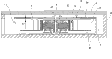
Please read Fig. 8, shown in Figure 9, it is that heat-dissipating fan one of the present utility model makes use-case, this impeller 3 is to be articulated in 1 one-tenth movable rotation of this pedestal, can drive air-flow by this flabellum 33 is moved towards second air port 12 by first air port 11, and the heater element 5 of being located at this second air port 12 dispelled the heat, this pedestal 1 and heater element 5 are to be incorporated into a casing 51, originally make in the middle of the use-case, this cover plate 2 is a machine plate of this casing 51, and form one first clearance G 1 between high-order bit T of this impeller and cover plate 2 bottoms, and 2 of an end of this auxiliary axis 4 and cover plates form this second clearance G 2, because this second clearance G 2 is less than first clearance G 1 (G2<G1), or these auxiliary axis 4 length L are greater than blade protrusion height H (L>H), originally it is concordant with impeller wheel hub top to make use-case middle fan leaf only be positioned at the impeller wheel hub side of this heat-dissipating fan, or the top of saying this flabellum do not protrude from the top of impeller wheel hub, so this flabellum protrusion height H=0.Therefore, when these impeller 3 rising displacements, only an end of this auxiliary axis 4 can be resisted against the bottom of this cover plate 2, so, the bottom (in the middle of present embodiment, can avoid flabellum 33 tops of this impeller 3 and the bottom that this cover plate 2 is collided at wheel hub 32 tops) that can avoid the high-order bit T of this impeller to collide this cover plate 2.
Please read shown in Figure 10; it is the another use-case that makes of heat-dissipating fan of the present utility model; be to constitute a heat-dissipating fan by an impeller 3 and a pedestal 1, and this heat-dissipating fan is provided with a protecting sheet 16 in addition, this protecting sheet 16 can be combined in pedestal 1 with existing buckle, adhesion or other various means of fixation.This protecting sheet 16 is positioned at flabellum 33 tops of this impeller 3; and form first air port 11 by this protecting sheet 16; fluid can be moved towards second air port 12 by first air port 11; promptly the thermal source that generated of this heater element 5 can be introduced by this first air port 11; and send by second air port 12 and to dispel the heat; this pedestal 1 and heater element 5 are incorporated into a casing 51, and this combination can be existing buckle, adhesion or other various means of fixation.Originally make in the middle of the use-case, this cover plate 2 is a machine plate of this casing 51.
Please read shown in Figure 11; this auxiliary axis 4 tools one length L; can form one second clearance G 2 between these auxiliary axis 4 one ends and cover plate 2 bottoms; form one first clearance G 1 ' between high-order bit T of this impeller and protecting sheet 16 bottoms; this second clearance G 2 is less than first clearance G 1 ' (G2<G1 '); or these auxiliary axis 4 length L are greater than blade protrusion height H (L>H); originally it is concordant with impeller wheel hub top to make use-case middle fan leaf only be positioned at the impeller wheel hub side of this heat-dissipating fan; or the top of saying this flabellum do not protrude from the top of impeller wheel hub, so this flabellum protrusion height H=0.Therefore; when these impeller 3 rising displacements, only an end of this auxiliary axis 4 can be resisted against the bottom of this cover plate 2, so; the bottom that still can avoid wheel hub 32 tops of this impeller 3 to collide this cover plate 2, and the bottom that can avoid these flabellum 33 tops to collide this protecting sheet 16.
Heat-dissipating fan described in the utility model, can be existing axial flow fan, centrifugal fan, blowing-type fan, advection formula fan etc., and this heat-dissipating fan is can drive air-flow to move in an air channel, this air-flow is flowed towards one the second air port in this air channel by at least one first air port in this air channel at least, is to have the knack of this technical field personage can expect and understanding.
Heat-dissipating fan described in the utility model can be existing external rotor type heat-dissipating fan, or be existing internal rotor type heat-dissipating fan, is to have the knack of this technical field personage can expect and understanding.
Top described in the utility model, bottom and side are according to drawing, and an end that is positioned at an object top position is the top, and an end that is positioned at a lower position is the bottom, are side connecting between this top and bottom.
Air channel described in the utility model, have first air port and second air port, this first air port and second air port can be formed on same substantially horizontal, or can be formed on same axial direction, or can be formed on non-same level and axial direction, or can be formed on mutually perpendicular direction, or can form the setting of any angle angle.
Cover plate described in the utility model can be for a plate that is formed on this heat-dissipating fan top, to protect the impeller of this heat-dissipating fan; Perhaps, this cover plate can be the machine plate for a casing of this heat-dissipating fan combination.
Flabellum described in the utility model, can be positioned at the impeller wheel hub side of this heat-dissipating fan, maybe can be positioned at the impeller wheel hub side of this heat-dissipating fan and protrude from the wheel hub top, maybe can be positioned at the impeller wheel hub side of this heat-dissipating fan and top, maybe can be positioned at the impeller wheel hub top of this heat-dissipating fan, be to have the knack of this technical field personage to be appreciated that.
Flabellum protrusion height H described in the utility model, be meant that this flabellum protrudes from the height at impeller wheel hub top, the impeller wheel hub side that only is positioned at this heat-dissipating fan when this flabellum is concordant with impeller wheel hub top, or the top of this flabellum is not when protruding from the top of impeller wheel hub, and this flabellum protrusion height H is zero.
Auxiliary axis described in the utility model, can be single element, or constituted by one first auxiliary axis and one second auxiliary axis, this auxiliary axis has a predetermined length L, or this first auxiliary axis is a predetermined length L1, this second auxiliary axis is a predetermined length L2, and the total length of this first auxiliary axis length L 1 and the second auxiliary axis length L 2 still is called length L, is to have the knack of this technical field personage to be appreciated that.
The high-order bit T of impeller described in the utility model is meant to protrude from the high-order bit of this impeller that when the top of this flabellum protruded from the wheel hub of this impeller, the high-order bit T of this impeller was the top of this flabellum; When the top of this flabellum did not protrude from the wheel hub top of this impeller, the high-order bit T of this impeller was the top of this wheel hub.The high-order bit T of impeller described in the utility model does not comprise the auxiliary axis that is positioned at this wheel hub top.
First clearance G 1 ' described in the utility model is meant the distance between high-order bit T of this impeller and the protecting sheet bottom.
Heat-dissipating fan of the present utility model, because this impeller wheel hub top is provided with auxiliary axis, therefore, heat-dissipating fan of the present utility model is to have the effect that impeller wheel hub top and flabellum top can not produce the collision effect with the cover plate bottom.
Heat-dissipating fan of the present utility model, the impeller wheel hub top of this heat-dissipating fan and flabellum top and cover plate bottom can not collided, therefore, heat-dissipating fan of the present utility model is to avoid this impeller noise generated because of colliding when rotation, and can reduce the effect of this heat-dissipating fan and impeller spoilage effect.
Heat-dissipating fan of the present utility model, owing to only increase by an auxiliary axis, therefore, heat-dissipating fan structure of the present utility model can be simplified, and the utlity model has the effect that reduces this heat-dissipating fan manufacture cost effect.
Heat-dissipating fan of the present utility model and impeller, owing to can be provided with an auxiliary axis at the wheel hub top of impeller, this auxiliary axis is to be resisted against this cover plate bottom, therefore, during the rotation of the impeller of heat-dissipating fan of the present utility model, has the effect of more firm effect.
Only the above person only is preferred embodiment of the present utility model, when not limiting the utility model practical range with this; So all simple equivalent of doing according to the utility model claim and description change and modify, all should still belong in the scope that the utility model patent contains.
Claims (18)
1. a heat-dissipating fan is characterized in that, comprising:
A pedestal;
A cover plate is positioned at the top of pedestal;
An impeller, by a rotatingshaft can movable rotation be articulated in pedestal, this impeller has high-order bit T, the high-order bit T of this impeller has one first clearance G 1 between bottom cover plate; And
An auxiliary axis is located between the wheel hub top and cover plate bottom of impeller, between this auxiliary axis and wheel hub top or the cover plate bottom one second clearance G 2 is arranged, and this second clearance G 2 is less than above-mentioned first clearance G 1.
2. heat-dissipating fan as claimed in claim 1; it is characterized in that this pedestal is provided with a protecting sheet, this protecting sheet is positioned at the flabellum top of this impeller; form one first clearance G 1 ' between high-order bit T of this impeller and the protecting sheet bottom, this second clearance G 2 is less than above-mentioned first clearance G 1 '.
3. heat-dissipating fan as claimed in claim 1, it is characterized in that, this auxiliary axis is made of one first auxiliary axis and one second auxiliary axis, this wheel hub top is provided with this first auxiliary axis, be provided with this second auxiliary axis in the bottom of cover plate, form second clearance G 2 between this first auxiliary axis and second auxiliary axis, this second clearance G 2 is less than above-mentioned first clearance G 1.
4. as claim 1,2 or 3 described heat-dissipating fan, it is characterized in that this impeller has a flabellum protrusion height H, this auxiliary axis has a length L, and this flabellum protrusion height H is less than the auxiliary axis length L.
5. heat-dissipating fan as claimed in claim 1 or 2 is characterized in that, this auxiliary axis is located at the wheel hub top of impeller.
6. heat-dissipating fan as claimed in claim 5 is characterized in that this auxiliary axis and impeller are one-body molded.
7. heat-dissipating fan as claimed in claim 1 or 2 is characterized in that this auxiliary axis is located at the bottom of cover plate.
8. as claim 1,2 or 3 described heat-dissipating fan, it is characterized in that this auxiliary axis is positioned at the rotating center position of this impeller.
9. as claim 1,2 or 3 described heat-dissipating fan, it is characterized in that this auxiliary axis is directly extended to form by this rotatingshaft.
10. heat-dissipating fan as claimed in claim 1 or 2 is characterized in that, this auxiliary axis forms circular-arc, taper or pointed in abutting connection with an end of cover plate bottom.
11. heat-dissipating fan as claimed in claim 3 is characterized in that, the abutting end of this first auxiliary axis and second auxiliary axis has at least an end to form circular-arc, taper or pointed.
12. heat-dissipating fan as claimed in claim 1 or 2 is characterized in that, this cover plate bottom is provided with an antifriction spare, and this antifriction spare can be for an end butt of auxiliary axis.
13., it is characterized in that this cover plate is combined on the pedestal as claim 1,2 or 3 described heat-dissipating fan.
14., it is characterized in that this heat-dissipating fan is incorporated into a casing as claim 1,2 or 3 described heat-dissipating fan, this cover plate is a machine plate of this casing.
15. as claim 1,2 or 3 described heat-dissipating fan, it is characterized in that this pedestal is provided with an air channel, this air channel has at least one first air port and at least one second air port, and be provided with an axle bed on this pedestal in addition, this impeller by a rotation axis hinge joint in this axle bed.
16. heat-dissipating fan as claimed in claim 15 is characterized in that, this first air port and second air port are formed on same substantially horizontal.
17. heat-dissipating fan as claimed in claim 15 is characterized in that, this first air port and second air port are formed on same axial direction.
18. heat-dissipating fan as claimed in claim 15 is characterized in that, this first air port and second air port are formed on mutually perpendicular direction.
Applications Claiming Priority (2)
| Application Number | Priority Date | Filing Date | Title |
|---|---|---|---|
| TW100114352 | 2011-04-25 | ||
| TW100114352A TWI453346B (en) | 2011-04-25 | 2011-04-25 | Cooling fan |
Publications (1)
| Publication Number | Publication Date |
|---|---|
| CN202073806U true CN202073806U (en) | 2011-12-14 |
Family
ID=44999649
Family Applications (2)
| Application Number | Title | Priority Date | Filing Date |
|---|---|---|---|
| CN201110119357.8A Expired - Fee Related CN102758784B (en) | 2011-04-25 | 2011-05-10 | Heat radiation fan |
| CN201120145895XU Expired - Lifetime CN202073806U (en) | 2011-04-25 | 2011-05-10 | Heat radiation fan |
Family Applications Before (1)
| Application Number | Title | Priority Date | Filing Date |
|---|---|---|---|
| CN201110119357.8A Expired - Fee Related CN102758784B (en) | 2011-04-25 | 2011-05-10 | Heat radiation fan |
Country Status (6)
| Country | Link |
|---|---|
| US (1) | US9140266B2 (en) |
| EP (1) | EP2518324B1 (en) |
| JP (1) | JP5308496B2 (en) |
| KR (1) | KR101256428B1 (en) |
| CN (2) | CN102758784B (en) |
| TW (1) | TWI453346B (en) |
Cited By (4)
| Publication number | Priority date | Publication date | Assignee | Title |
|---|---|---|---|---|
| CN102758784A (en) * | 2011-04-25 | 2012-10-31 | 建准电机工业股份有限公司 | Heat radiation fan |
| CN103511338A (en) * | 2012-06-29 | 2014-01-15 | 协禧电机股份有限公司 | Fan structure |
| CN103541916A (en) * | 2012-07-09 | 2014-01-29 | 建准电机工业股份有限公司 | Blowing type heat radiation fan |
| CN109654041A (en) * | 2017-10-10 | 2019-04-19 | 英业达科技有限公司 | Fan mould group |
Families Citing this family (10)
| Publication number | Priority date | Publication date | Assignee | Title |
|---|---|---|---|---|
| JP5665802B2 (en) * | 2012-07-05 | 2015-02-04 | ミネベア株式会社 | Centrifugal fan |
| CN104343702A (en) * | 2013-07-25 | 2015-02-11 | 纬创资通股份有限公司 | Fan device and electronic device |
| CN104684309A (en) * | 2013-11-29 | 2015-06-03 | 英业达科技有限公司 | Electronic device |
| TWI501718B (en) * | 2013-12-17 | 2015-09-21 | Inventec Corp | Electronic device |
| JP2018178802A (en) * | 2017-04-07 | 2018-11-15 | 日本電産株式会社 | Fan motor |
| CN112081762B (en) * | 2019-06-13 | 2023-01-31 | 苏州凯航电机有限公司 | Electric fan and cleaning equipment |
| TWI725683B (en) | 2019-12-24 | 2021-04-21 | 建準電機工業股份有限公司 | Impeller and cooling fan including the same |
| CN113225996A (en) * | 2021-05-13 | 2021-08-06 | 吉林师范大学 | Computer network signal transmission stabilising arrangement |
| US20230089324A1 (en) * | 2021-09-17 | 2023-03-23 | Rakuten Mobile, Inc. | Sentiment analysis |
| US11835287B2 (en) | 2022-02-02 | 2023-12-05 | Whirlpool Corporation | Refrigeration unit |
Family Cites Families (17)
| Publication number | Priority date | Publication date | Assignee | Title |
|---|---|---|---|---|
| TW314223U (en) * | 1995-11-06 | 1997-08-21 | Nippon Keiki Works Co Ltd | Cooling radiator |
| JP3307847B2 (en) * | 1997-01-31 | 2002-07-24 | ホシザキ電機株式会社 | Blowers such as refrigerators |
| JPH1175340A (en) * | 1997-06-17 | 1999-03-16 | Nippon Densan Corp | Motor |
| DE29914693U1 (en) * | 1998-09-01 | 2000-01-13 | Papst Motoren Gmbh & Co Kg | Axial fan with an external rotor drive motor |
| TW581158U (en) * | 2003-03-31 | 2004-03-21 | Delta Electronics Inc | Side-blown fan |
| US7416388B2 (en) | 2003-07-02 | 2008-08-26 | Delta Electronics, Inc. | Fan |
| TWI222263B (en) * | 2003-08-15 | 2004-10-11 | Delta Electronics Inc | Non-bearing motor |
| US20050265834A1 (en) * | 2004-05-28 | 2005-12-01 | Harvatek Corporation | Fan structure |
| US20060078423A1 (en) * | 2004-10-08 | 2006-04-13 | Nonlinear Tech, Inc. | Bi-directional Blowers for Cooling Laptop Computers |
| US7390166B2 (en) * | 2005-11-15 | 2008-06-24 | Zippy Technology Corp. | Rotary structure for radiation fans |
| US20070166156A1 (en) | 2006-01-13 | 2007-07-19 | Chih-Min Li | Cooling fan with dynamic and static blades |
| US20080181772A1 (en) | 2007-01-29 | 2008-07-31 | Wen-Hao Liu | Conductive device for cooling fan with luminous figures |
| CN101382154B (en) | 2007-09-07 | 2011-06-08 | 富准精密工业(深圳)有限公司 | Centrifugal fan |
| TW200928113A (en) | 2007-12-26 | 2009-07-01 | Delta Electronics Inc | Heat dissipation module and fan thereof |
| TWM351277U (en) * | 2008-09-25 | 2009-02-21 | Risun Expanse Corp | Positioning structure of fan |
| TWM371180U (en) * | 2009-06-26 | 2009-12-21 | Micro Star Int Co Ltd | Position-limiting structure of fan |
| TWI453346B (en) * | 2011-04-25 | 2014-09-21 | Sunonwealth Electr Mach Ind Co | Cooling fan |
-
2011
- 2011-04-25 TW TW100114352A patent/TWI453346B/en not_active IP Right Cessation
- 2011-05-10 CN CN201110119357.8A patent/CN102758784B/en not_active Expired - Fee Related
- 2011-05-10 CN CN201120145895XU patent/CN202073806U/en not_active Expired - Lifetime
- 2011-08-08 US US13/204,755 patent/US9140266B2/en not_active Expired - Fee Related
- 2011-09-22 JP JP2011206888A patent/JP5308496B2/en not_active Expired - Fee Related
- 2011-10-20 EP EP11008430.8A patent/EP2518324B1/en not_active Not-in-force
- 2011-10-26 KR KR1020110109733A patent/KR101256428B1/en active IP Right Grant
Cited By (7)
| Publication number | Priority date | Publication date | Assignee | Title |
|---|---|---|---|---|
| CN102758784A (en) * | 2011-04-25 | 2012-10-31 | 建准电机工业股份有限公司 | Heat radiation fan |
| CN102758784B (en) * | 2011-04-25 | 2015-04-15 | 建准电机工业股份有限公司 | Heat radiation fan |
| CN103511338A (en) * | 2012-06-29 | 2014-01-15 | 协禧电机股份有限公司 | Fan structure |
| CN103541916A (en) * | 2012-07-09 | 2014-01-29 | 建准电机工业股份有限公司 | Blowing type heat radiation fan |
| CN103541916B (en) * | 2012-07-09 | 2016-04-06 | 建准电机工业股份有限公司 | Blowing type heat radiation fan |
| CN109654041A (en) * | 2017-10-10 | 2019-04-19 | 英业达科技有限公司 | Fan mould group |
| CN109654041B (en) * | 2017-10-10 | 2020-12-29 | 英业达科技有限公司 | Fan module |
Also Published As
| Publication number | Publication date |
|---|---|
| CN102758784B (en) | 2015-04-15 |
| KR20120120887A (en) | 2012-11-02 |
| EP2518324A2 (en) | 2012-10-31 |
| TWI453346B (en) | 2014-09-21 |
| EP2518324B1 (en) | 2016-09-28 |
| KR101256428B1 (en) | 2013-04-18 |
| US20120269617A1 (en) | 2012-10-25 |
| CN102758784A (en) | 2012-10-31 |
| JP2012229689A (en) | 2012-11-22 |
| JP5308496B2 (en) | 2013-10-09 |
| US9140266B2 (en) | 2015-09-22 |
| TW201243166A (en) | 2012-11-01 |
| EP2518324A3 (en) | 2013-08-14 |
Similar Documents
| Publication | Publication Date | Title |
|---|---|---|
| CN202073806U (en) | Heat radiation fan | |
| CN101382154B (en) | Centrifugal fan | |
| CN203707950U (en) | Motor with thrust bearing | |
| JP2006226211A (en) | Blower | |
| CN103441612A (en) | Magnetic suspension permanent-magnet synchronous high-power high-speed draught fan | |
| CN104454635B (en) | Blower fan | |
| CN201391489Y (en) | Dustproof heat radiating fan | |
| CN204376573U (en) | Motor and cooling fan with same | |
| CN105308326A (en) | Pump arrangement and method for producing a containment shell for the pump arrangement | |
| CN203163108U (en) | Outdoor unit of top air-blowing air conditioner | |
| CN205013334U (en) | axial induction motor fan | |
| CN203482014U (en) | Magnetic suspension permanent-magnet synchronous high-power high-speed draught fan | |
| CN205195441U (en) | Brushless fan motor of direct current and fan | |
| CN209692435U (en) | Default sub-component and blade and outer rotor integral fan | |
| CN202178632U (en) | Motor capable of preventing rotor from being separated and separation-preventing assembly thereof | |
| CN207968111U (en) | Motor rotor | |
| CN107070127A (en) | Rotor guider is used in the assembling of internal rotor traction machine | |
| CN203774938U (en) | Motor with thrust bearing | |
| CN206571739U (en) | A kind of new motor shell flabellum | |
| CN203214420U (en) | Propeller type fan and air conditioner | |
| CN106762826B (en) | Novel motor shell fan blade | |
| CN108631493B (en) | Motor end cover and reluctance motor | |
| CN213541082U (en) | Air bearing | |
| CN103711729A (en) | Centrifugal radiating fan system and centrifugal radiating fan thereof | |
| CN102111023B (en) | Motor rotating part |
Legal Events
| Date | Code | Title | Description |
|---|---|---|---|
| C14 | Grant of patent or utility model | ||
| GR01 | Patent grant | ||
| AV01 | Patent right actively abandoned |
Granted publication date: 20111214 Effective date of abandoning: 20150415 |
|
| AV01 | Patent right actively abandoned |
Granted publication date: 20111214 Effective date of abandoning: 20150415 |
|
| RGAV | Abandon patent right to avoid regrant |