CN202067659U - Current transformer - Google Patents
Current transformer Download PDFInfo
- Publication number
- CN202067659U CN202067659U CN2011201008229U CN201120100822U CN202067659U CN 202067659 U CN202067659 U CN 202067659U CN 2011201008229 U CN2011201008229 U CN 2011201008229U CN 201120100822 U CN201120100822 U CN 201120100822U CN 202067659 U CN202067659 U CN 202067659U
- Authority
- CN
- China
- Prior art keywords
- current transformer
- coil
- circuit board
- electronic circuit
- housing
- Prior art date
- Legal status (The legal status is an assumption and is not a legal conclusion. Google has not performed a legal analysis and makes no representation as to the accuracy of the status listed.)
- Expired - Lifetime
Links
Images

Abstract
A current transformer relates to the field of low-voltage apparatus and comprises a shell, a containing cavity is formed inside the shell, a coil is disposed inside the containing cavity, an electronic circuit board electrically connected with the coil and provided with a rectifier circuit is further mounted in the containing cavity, and a socket is mounted on the electronic circuit board. By adopting the technical scheme, the current transformer without outgoing lines is convenient in mounting during production or change in after-sale service, rejection of the whole current transformer due to damage of the outgoing lines of the current transformer is avoided, and cost consumption in production is reduced. The rectifier circuit is disposed inside the current transformer, so that energy signals of the current transformer are outputted as pulse signals, size of an intelligent controller is reduced, and implementation of miniature of the intelligent controller is benefited.
Description
Technical field
The utility model relates to a kind of current transformer, belongs to the low-voltage electrical apparatus field.
Background technology
The lead-out wire of existing circuit breaker Current Transformer directly is connected to intelligent controller, misoperation or the current transformer lead-out wire that causes lack of standardization is installed is damaged in the circuit breaker production process, this current transformer just can't continue to use so, must dismantle circuit breaker again and new current transformer is installed, increase production cost thus, locate the user, if the current transformer of circuit breaker breaks down, the on-the-spot very trouble of changing of after-sale service personnel, except needs from circuit breaker rear dismounting current transformer, also need from parts such as circuit breaker the place ahead dismounting intelligent controllers.And the structure of present current transformer is not suitable for the requirement of current circuit breaker miniaturization.
Summary of the invention
The utility model is to overcome the deficiencies in the prior art, provides a kind of and can make the circuit breaker miniaturization, and change simply the current transformer that reduces production costs.
The utility model is achieved through the following technical solutions: a kind of current transformer, comprise shell, described enclosure forms a cavity volume, the inner coil of placing of described cavity volume, the electronic circuit board that is electrically connected with coil also is installed in the described cavity volume, described electronic circuit board is provided with socket, and this socket is used to connect the current transformer lead-out wire.
Also have a rectification circuit on the described electronic circuit board, the input of described rectification circuit is connected with coil, and the output of described rectification circuit is connected with socket.
Described shell is fastened and connected and is formed by first housing, second housing.
Described first housing offers a groove.
Be equipped with two draw-in grooves that electronic circuit board is installed in the described groove.
Also offer the cavity that holds socket on the described groove.
The present invention adopts technique scheme, compared with prior art has following advantage:
The utility model is owing to adopt technique scheme, current transformer does not have lead-out wire, in the production process or after-sale service easy for installation when changing, avoid because the damage of current transformer lead-out wire causes whole current transformer to be scrapped cost depletions in the reduction production process.Rectification circuit is built in the current transformer, makes the current transformer energy signal be output as fluctuating signal, has saved the volume of intelligent controller, helps intelligent controller and realizes miniaturization.
Description of drawings
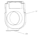
Fig. 1 is the utility model structural representation
Fig. 2 is the schematic diagram of housing 11 of the present utility model
Fig. 3 is the schematic diagram of housing 12 of the present utility model
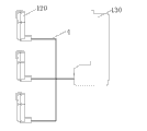
Fig. 4 is the schematic diagram that the utility model is connected with the external smart controller
Wherein, 1, shell 3, coil 4, connecting line assembly 5, silicon steel sheet 6, insulating cell 7, wiring board 11, first housing 12, second housing 13, cavity volume 14, busbar resigning hole 31, energy coil 32, measure coil 71, socket 111, groove 112, two draw-in grooves 113, cavity 114, window 120, current transformer 121, baffle plate 130, intelligent controller
Embodiment
In order to make the public can fully understand technical spirit of the present utility model and beneficial effect; to describe in detail embodiment of the present utility model in conjunction with the accompanying drawings below; but to the description of embodiment is not restriction to technical scheme, anyly makes form but not the variation of essence all should be considered as protection range of the present utility model according to the utility model design.
See also Fig. 1, a kind of current transformer, comprise by first housing 11, the shell 1 of the busbar resigning hole 14 that is used to wear on the busbar is formed and had to second housing 12, housing 11 and housing 12 constitute a cavity volume 13, be packaged in the coil 3 in the cavity volume 13, described coil 3 comprises energy coil 31 and measures coil 32, also be packaged with the silicon steel sheet 5 that is arranged in the energy coil 31 in the cavity volume 13, be used to separate energy coil 31 and the insulating cell 6 of measuring coil 32, the electronic circuit board 7 that is electrically connected and has rectification circuit with coil 3 also is installed in the described cavity volume 13, is equiped with socket 71 on the described electronic circuit board 7 and is used to connect the current transformer lead-out wire.
See also Fig. 2, offer a groove 111 on the described housing 11.Be equipped with two draw-in grooves 112 that electronic circuit board 7 is installed in the described groove 111.Offer the cavity 113 that holds socket 71 on the described groove 111.Also offer one on the outer wall of described groove 111 and the lead-out wire of energy coil 31 is welded to window 114 on the electronic circuit board 7 after being convenient in electronic circuit board 7 is installed to groove 111.
See also Fig. 3, be equipped with one on the described housing 12 and be used for the baffle plate 121 that matches with described window 114.
See also Fig. 1,2,3,4, the silicon steel sheet 5 that at first will be equipped with energy coil 31 is installed in the housing 12, installing the back fixes with the silica gel embedding, then will measure in the housing 11 of packing into after the socket 71 of coil 32 on the electronic circuit board 7 with rectification circuit is electrically connected, electronic circuit board 7 is installed in the groove of offering on the housing 11 111 by two draw-in grooves 112 on the housing 11, the output socket that be installed in the socket 71 on the electronic circuit board 7 this moment just in time falls in the cavity of offering on the groove 111 113, and the output socket of socket 71 can be connected with the external smart controller by coupling assembling 4.Then again with the lead-out wire of energy coil 31 with after electronic circuit board 7 is electrically connected, export socket 71 to after the rectification circuit rectification by electronic circuit board 7, pass through socket 71 again and be connected with the external smart controller with connecting line assembly 4.Wherein socket 71 is six needle sockets.Last will be used to separate energy coil 31 and the insulating cell 6 of measuring coil 32 again and pack between energy coil 3 and the measurement coil 4 after, housing 11 and housing 12 usefulness are clamped or put mode such as glue installation and be installed together, form a current transformer.
Claims (8)
1. current transformer, comprise shell (1), the inner cavity volume (13) that forms of described shell (1), the inner coil (3) of placing of described cavity volume (13), it is characterized in that, the electronic circuit board (7) that is electrically connected with coil (3) also is installed in the described cavity volume (13), and described electronic circuit board (7) is provided with socket (71).
2. a kind of current transformer according to claim 1, it is characterized in that, described electronic circuit board also has a rectification circuit on (7), and the input of described rectification circuit is connected with coil (3), and the output of described rectification circuit is connected with socket (71).
3. a kind of current transformer according to claim 1 is characterized in that, described shell (1) is fastened and connected and is formed by first housing (11), second housing (12).
4. a kind of current transformer according to claim 2 is characterized in that, offers a groove (111) on the described housing (11).
5. a kind of current transformer according to claim 3 is characterized in that, is equipped with two draw-in grooves (112) that electronic circuit board (7) is installed in the described groove (111).
6. according to claim 3 or 4 described a kind of current transformers, it is characterized in that, also offer the cavity (113) that holds socket (71) on the described groove (111).
7. according to claim 3 or 4 described a kind of current transformers, it is characterized in that, also offer window (114) on the outer wall of described groove (111).
8. a kind of current transformer according to claim 2 is characterized in that, is equipped with one on the described housing (12) and is used for the baffle plate (121) that matches with described window (114).
Priority Applications (1)
| Application Number | Priority Date | Filing Date | Title |
|---|---|---|---|
| CN2011201008229U CN202067659U (en) | 2011-04-08 | 2011-04-08 | Current transformer |
Applications Claiming Priority (1)
| Application Number | Priority Date | Filing Date | Title |
|---|---|---|---|
| CN2011201008229U CN202067659U (en) | 2011-04-08 | 2011-04-08 | Current transformer |
Publications (1)
| Publication Number | Publication Date |
|---|---|
| CN202067659U true CN202067659U (en) | 2011-12-07 |
Family
ID=45061516
Family Applications (1)
| Application Number | Title | Priority Date | Filing Date |
|---|---|---|---|
| CN2011201008229U Expired - Lifetime CN202067659U (en) | 2011-04-08 | 2011-04-08 | Current transformer |
Country Status (1)
| Country | Link |
|---|---|
| CN (1) | CN202067659U (en) |
Cited By (2)
| Publication number | Priority date | Publication date | Assignee | Title |
|---|---|---|---|---|
| CN103795399A (en) * | 2014-01-17 | 2014-05-14 | 上海磊跃自动化设备有限公司 | Mutual inductor for rectifier type low-voltage circuit breaker |
| CN105575638A (en) * | 2014-10-12 | 2016-05-11 | 朱佳瑞 | Mutual inductor housing |
-
2011
- 2011-04-08 CN CN2011201008229U patent/CN202067659U/en not_active Expired - Lifetime
Cited By (2)
| Publication number | Priority date | Publication date | Assignee | Title |
|---|---|---|---|---|
| CN103795399A (en) * | 2014-01-17 | 2014-05-14 | 上海磊跃自动化设备有限公司 | Mutual inductor for rectifier type low-voltage circuit breaker |
| CN105575638A (en) * | 2014-10-12 | 2016-05-11 | 朱佳瑞 | Mutual inductor housing |
Similar Documents
| Publication | Publication Date | Title |
|---|---|---|
| CN203085344U (en) | Integrated digital current transformer | |
| CN201332015Y (en) | Electron type current transformer | |
| CN208314040U (en) | A kind of ammeter with harmonic measurement function | |
| CN202067659U (en) | Current transformer | |
| CN201893232U (en) | Open type current transformer | |
| CN102360871B (en) | Mutual inductor packaging assembly | |
| CN207691435U (en) | A kind of integral intelligent control metering reactive-load dynamic compensation unit | |
| CN202957335U (en) | Storage battery with battery management system module | |
| CN204809948U (en) | Wireless changer casing | |
| CN203607788U (en) | Novel wall bushing | |
| CN202816636U (en) | Novel casing pipe mutual inductor | |
| CN202189668U (en) | Mutual inductor encapsulation component | |
| CN204614654U (en) | A kind of instant-plugging current transformer device | |
| CN217980406U (en) | Wireless temperature vibration sensor | |
| CN202256433U (en) | Electric energy meter junction box and electric energy meter | |
| CN204441081U (en) | A kind of condenser bushing formula current transformer | |
| CN201203638Y (en) | Upper-in lower-out electronic single-phase electric energy gauge based on identical connection terminal seat | |
| CN204287353U (en) | Charger performance parameter testing system and tool | |
| CN204614653U (en) | Copper bar installed by a kind of instant-plugging current transformer | |
| CN208224430U (en) | A kind of patch capacitor performance evaluation device | |
| CN216410225U (en) | Quick response low-power consumption electric quantity transmitter device | |
| CN217819044U (en) | Temperature and acoustic leakage discharge telemetering module for box transformer substation and switching station cabinet | |
| CN201489995U (en) | Busbar nesting type low-voltage current transformer | |
| CN202384714U (en) | Wall feed-through sleeve provided with high voltage lead | |
| CN220020803U (en) | Energy-saving and environment-friendly dry-type transformer |
Legal Events
| Date | Code | Title | Description |
|---|---|---|---|
| C14 | Grant of patent or utility model | ||
| GR01 | Patent grant | ||
| CX01 | Expiry of patent term | ||
| CX01 | Expiry of patent term |
Granted publication date: 20111207 |