CN202065122U - Wind power generation device - Google Patents
Wind power generation device Download PDFInfo
- Publication number
- CN202065122U CN202065122U CN 201120186563 CN201120186563U CN202065122U CN 202065122 U CN202065122 U CN 202065122U CN 201120186563 CN201120186563 CN 201120186563 CN 201120186563 U CN201120186563 U CN 201120186563U CN 202065122 U CN202065122 U CN 202065122U
- Authority
- CN
- China
- Prior art keywords
- rotating disk
- links
- pendulum leaf
- permanent magnet
- generating unit
- Prior art date
- Legal status (The legal status is an assumption and is not a legal conclusion. Google has not performed a legal analysis and makes no representation as to the accuracy of the status listed.)
- Expired - Fee Related
Links
Images


Classifications
-
- Y—GENERAL TAGGING OF NEW TECHNOLOGICAL DEVELOPMENTS; GENERAL TAGGING OF CROSS-SECTIONAL TECHNOLOGIES SPANNING OVER SEVERAL SECTIONS OF THE IPC; TECHNICAL SUBJECTS COVERED BY FORMER USPC CROSS-REFERENCE ART COLLECTIONS [XRACs] AND DIGESTS
- Y02—TECHNOLOGIES OR APPLICATIONS FOR MITIGATION OR ADAPTATION AGAINST CLIMATE CHANGE
- Y02E—REDUCTION OF GREENHOUSE GAS [GHG] EMISSIONS, RELATED TO ENERGY GENERATION, TRANSMISSION OR DISTRIBUTION
- Y02E10/00—Energy generation through renewable energy sources
- Y02E10/70—Wind energy
- Y02E10/74—Wind turbines with rotation axis perpendicular to the wind direction
Abstract
The utility model discloses a wind power generation device, which belongs to the technical field of wind motors. The utility model provides the wind power generation device with a simple structure, working reliability, high wind energy use ratio and low noise. The wind power generation device comprises a substrate. The substrate is provided with a supporting rod. The wind power generation device has the structural main points that the lower part of the supporting rod is provided with a first turntable; a first cross beam is fixed at the outer side of the first turntable; the first cross beam is connected with one end of an arc-shaped camber beam with a stator winding; the other end of the arc-shaped camber beam is connected with a second cross beam on a second turntable through a pull rod, wherein the second turntable is arranged at the upper part of the supporting rod; the second cross beam at both sides of the supporting rod is symmetrically provided with swing blades; the upper ends of the swing blades are connected with the second cross beam through swing blade shafts; the lower ends of the swing blades are respectively provided with a permanent magnet corresponding to the stator winding; the tail end of the second cross beam is connected with a third turntable at the top part of the supporting rod through a tension cable; the third turntable is connected with a rudder; and the first turntable, the second turntable and the third turntable are connected through a connecting rod.
Description
Technical field
The utility model is divided by International Patent Classification (IPC) (IPC) and is belonged to mechanical engineering, illumination, heating, weapon, explosion portion, hydraulic machine or fluid motor; The big class of wind-force, elastic force or gravitation engine, wind motor group technical field relates in particular to a kind of wind generating unit.
Background technique
Existing wind generating unit mostly is a horizontal axis wind-driven generator, utilize pylon that oar blade type generator, booster engine etc. are installed in the air, this just makes requirement of mechanical strength to pylon than higher, and complex structure, high material consumption, gross mass are big generally, and some parts single-piece is heavy, volume is big.For the blower fan of MW class, even surpass hundred tons, the enterprise that possesses this throughput is very few, all is a test for the bearing capacity of crane tonnage and road.These reasons have caused the cost of aspects such as the production, construction, operation management of horizontal axis wind-driven generator higher.
In addition, existing generator operating range is narrow, and when wind speed was higher than rated wind speed, output power can surpass rated power, and generator will produce problems of excessive heat like this.Wind energy conversion system producer takes to limit wind energy conversion system with regard to having to rotating speed solves the overload problem of generator, and the energy changing scope that wind-driven generator is accepted will be at several times, tens times even more.The frequent variations of so going round and beginning again is difficult to adapt on the existing electric generator structure, and it is very difficult working in wide range like this, or even impossible.
And existing wind energy conversion system mostly adopts wind wheel type, and according to Bates (Bets) theory, there is a limiting value (59%) in the wind wheel type wind energy conversion system on capturing wind energy, and utilization ratio is low.
Summary of the invention
The utility model is exactly at the problems referred to above, and a kind of simple in structure, reliable operation, wind energy utilization height, wind generating unit that noise is little are provided.
For achieving the above object, the utility model adopts following technological scheme, the utility model comprises pedestal, pedestal is provided with strut, its structure outline strut bottom is provided with first rotating disk, first rotating disk outside is fixed with first crossbeam, and first crossbeam links to each other with an end of the arc camber beam with staor winding, and the other end of arc camber beam links to each other with second crossbeam on second rotating disk that is arranged on strut top by pull bar; Be symmetrically arranged with the pendulum leaf on second crossbeam of strut both sides, the upper end of pendulum leaf links to each other with second crossbeam by the pendulum rachis, and the lower end of pendulum leaf is provided with permanent magnet corresponding to staor winding; The end of second crossbeam links to each other with the 3rd rotating disk of support bar top by drag-line, and the 3rd rotating disk links to each other with rudder, and first rotating disk, second rotating disk, the 3rd rotating disk link to each other by connecting rod.
As a kind of preferred version, staor winding described in the utility model is at least one, arranges along the swinging track of pendulum leaf lower end.
As another kind of preferred version, permanent magnet described in the utility model comprises N utmost point permanent magnet and S utmost point permanent magnet, and N utmost point permanent magnet and S utmost point permanent magnet are oppositely arranged in the U-shaped framework, and U-shaped framework upper end links to each other with pendulum leaf lower end.
As another kind of preferred version, the blade of pendulum leaf described in the utility model is provided with the round table-like through hole of windward side opening area greater than the leeward side opening area.
As another kind of preferred version, the blade interior filling foamed plastics of pendulum leaf described in the utility model, surperficial coated metal covering.
As another kind of preferred version, the blade of pendulum leaf described in the utility model is provided with at least one movable gate.Piston rod by oil hydraulic cylinder stretch control movable gate unlatching with closed.
As another kind of preferred version, second rotating disk described in the utility model links to each other with strut by bearing, back-up ring.
As another kind of preferred version, staor winding described in the utility model links to each other with electrical network by rectification module, inversion module.
Secondly, the output terminal of rectification module described in the utility model links to each other with battery pack.
In addition, strut described in the utility model adopts steel pipe.
The utility model beneficial effect: (1) the utility model has been cancelled a series of members such as the blade that existing wind-driven generator had, wheel hub, pitched device, break, speed-changing gear box, rotary generator, yaw drive in that to utilize wind energy to change in the design of mechanical energy very big with the difference structurally of existing wind-driven generator.Though increased the pendulum leaf, pendulum leaf and blade quality are about the same; Dull and stereotyped generator (permanent magnet, staor winding) is installed in the bottom, unlike the existing level axis wind power generator, is installed in the top of pylon, has reduced center of gravity the force-bearing property of pylon is improved.So the utility model total quality greatly reduces, the quality of maximum single component is far smaller than existing wind-driven generator, the corresponding cost of having saved transportation, lifting.Saved the construction and the operation expense of wind energy turbine set generally significantly, strengthened competitive ability with thermoelectricity and the generating of other forms.
(2) the utility model generator does not have exciting winding, does not consume exciting power; Generator does not have slip ring, safety and reliability during running; Manufacturing process is simple, does not need basically to safeguard.
(3) operating range is wide.Because the utility model is the swing by permanent magnet the coil cutting magnetic line of staor winding is generated electricity, so the coil of staor winding can expose and be installed on the arc camber beam, rapid heat dissipation does not need speed limiting device.
(4) the startup wind speed is low, can do non-loaded startup.The utility model adopts swinging impeller structure, and low wind speed just can start; When the pendulum leaf is perpendicular to the ground, can not set sub-winding under the pendulum leaf, not generate electricity when starting like this, be easy to start.
(5) noise free pollutes, migration of birds is not had obstruction.Certain noise is arranged during the blade rotation of prior three-blade blower fan.The sound that the swing of the utility model pendulum leaf produces is than much smaller.When the blade rotation of three leaf blower fans was got up, the blade point had very high linear velocity, can cause injures and deaths when birds fly over, and also can cause certain infringement to blower fan.The utility model is tangible pendulum leaf, just can see from far, can avoid birds to bump against on the utility model.
(6) the utility model is because the parts of transformation of energy adopt is pendulum leaf rather than wind wheel, thereby can not be subjected to the restriction of limiting value 59% on wind energy utilization; The wind energy utilization height.
Description of drawings
Below in conjunction with the drawings and specific embodiments the utility model is described further.The utility model protection domain not only is confined to the statement of following content.
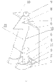
Fig. 1 is the utility model structural representation.
Fig. 2 is the utility model front view.
Fig. 3 is the left view of Fig. 2 under windless condition.
To be Fig. 2 reach a left view when regularly putting leaf and being blown up several angle at wind speed to Fig. 4.
Fig. 5 is the utility model staor winding and permanent magnet relative position structural representation.
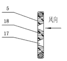
Fig. 6 is the utility model pendulum leaf blade structure schematic representation.
Fig. 7 is the B-B sectional view of Fig. 6.
Fig. 8 is the utility model swinging impeller structure schematic representation.
Fig. 9 is the utility model second crossbeam and strut Placement structural representation.
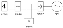
Figure 10 is the utility model electric energy transfer principle block diagram.
Figure 11 is the utility model movable gate opening state schematic representation.
Among the figure, 1 is that first crossbeam, 2 is that arc camber beam, 3 is that U-shaped framework, 4 is strut
, 5 for pendulum leaf, 6 be second crossbeam, 7 be second rotating disk, 8 for rudder, 9 be the 3rd rotating disk, 10 for drag-line, 11 be first rotating disk, 12 for pull bar, 13 for the pendulum rachis, 14 for N utmost point permanent magnet, 15 for staor winding, 16 for S utmost point permanent magnet, 17 for through hole, 18 for foamed plastics, 19 for back-up ring, 20 for bearing, 21 for connecting rod, 22 for pedestal, 23 for movable gate, 24 for draw ring, 25 for piston rod, 26 for oil hydraulic cylinder.
Embodiment
Shown in Fig. 1,2,3,4, the utility model comprises pedestal 22, pedestal 22 is provided with strut 4, strut 4 bottoms are provided with first rotating disk 11, first rotating disk, 11 outsides are fixed with first crossbeam 1, first crossbeam 1 links to each other with an end of the arc camber beam 2 with staor winding 15, and the other end of arc camber beam 2 links to each other with second crossbeam 6 on second rotating disk 7 that is arranged on strut 4 tops by pull bar 12; Be symmetrically arranged with pendulum leaf 5 on second crossbeam 6 of strut 4 both sides, the upper end of pendulum leaf 5 links to each other with second crossbeam 6 by pendulum rachis 13, and the lower end of pendulum leaf 5 is provided with permanent magnet corresponding to staor winding 15; The end of second crossbeam 6 links to each other with the 3rd rotating disk 9 at strut 4 tops by drag-line 10, the 3rd rotating disk 9 links to each other with rudder 8, first rotating disk 11, second rotating disk 7, the 3rd rotating disk 9 link to each other by connecting rod 21, make rudder 8, second crossbeam 6, connecting rod 21, first crossbeam 1 be fixed into one, can one common peripheral rotate around strut 4.
Described staor winding 15 is at least one, arranges along the swinging track of pendulum leaf 5 lower ends; A plurality of staor winding 15 are separate, and each staor winding 15 is equivalent to a little generator.
Described pedestal 22 can be reinforced concrete independence pedestal, and pedestal 22 can adopt stone bolt formula Connecting format with being connected of strut 4.
When described rudder 8 and wind direction are not parallel, will produce a moment of torsion, drive second crossbeam 6 and wait other rotary parts to rotate together to make pendulum leaf 5 aligning wind directions, need not external control can realize purpose to wind.
As shown in Figure 5, described permanent magnet comprises N utmost point permanent magnet 14 and S utmost point permanent magnet 16, and N utmost point permanent magnet 14 and S utmost point permanent magnet 16 are oppositely arranged in the U-shaped framework 3, and U-shaped framework 3 upper ends link to each other with pendulum leaf 5 lower ends; Distance between N utmost point permanent magnet 14 and the S utmost point permanent magnet 16 can slip over smoothly, not have jam and be as the criterion with staor winding 15.When permanent magnet during along with pendulum leaf 5 reciprocally swingings, thereby the stator coil between N utmost point permanent magnet 14 and S utmost point permanent magnet 16 is done the relative movement of the cutting magnetic field magnetic line of force and is produced electric current.
Described staor winding 15 is to coil on the iron core that is stamped to form.In order to improve generator efficiency, reduce the copper loss of stator, adopts bigger winding conductor cross section, the concrete number of turn and line are directly looked generator capacity and taking all factors into consideration then calmly economically.Staor winding 15 is by being bolted on the arc camber beam 2, and it is convenient to install, overhaul.Staor winding 15 is on the track that always is in space motion between N utmost point permanent magnet 14 and the S utmost point permanent magnet 16 on the spatial position, no matter where N utmost point permanent magnet 14 and S utmost point permanent magnet 16 are in pendulum leaf 5, always the Normal direction of staor winding 15 coil planes is located to such an extent that magnetic direction is vertical with the coil place.Stator coil is along the circular path layout of pendulum leaf 5 lower ends and divides into groups that the path length that takies is the amount doesn't matter, relatively flexibly, but should be greater than the permanent magnet length that pendulum leaf 5 lower ends are installed.During work, because wind speed is all to be at any time in the variation, single staor winding 15 can always not be in working state, but some staor winding 15 alternations.In addition, stator coil is exposed being installed on the arc camber beam 2, and radiating condition is better, this speed limit measure with regard to having avoided existing generator overheating problem and having had to take wind energy conversion system for fear of the problems of excessive heat of generator.
Shown in Fig. 6,7,8, the blade of described pendulum leaf 5 is provided with the round table-like through hole 17 of windward side opening area greater than the leeward side opening area; The blade interior filling foamed plastics 18 of described pendulum leaf 5, surperficial coated metal covering; Can increase and catch the wind effect.
As shown in figure 11, the blade of described pendulum leaf 5 is provided with at least one movable gate 23; To increase the amplitude of fluctuation and the frequency of pendulum leaf 5.
The middle part of described movable gate 23 is fixed with draw ring 24, and draw ring 24 links to each other with the oil hydraulic cylinder 26 of draw ring 24 tops by piston rod 25; By regulator solution cylinder pressure 26 length of piston rod 25 is set, thereby regulates the open angle of movable gate 23, can avoid when wind-force, wind direction change hour, the variation of the angle that pendulum leaf 5 put is less, influences the effect of generating electricity.
As shown in Figure 9, described second rotating disk 7 links to each other with strut 4 by bearing 20, back-up ring 19; First rotating disk 11 can adopt same way as with being connected also of strut 4.
As shown in figure 10, described staor winding 15 links to each other with electrical network by rectification module, inversion module; Because the utility model is bigger with the rotary generator difference of operation now, it is the staor winding 15 that constitutes by multi-thread circle, though the electric current that sends in each generating pitch of the laps also is to exchange, but the effective value of its voltage and wave mode must be handled the requirement that just can meet electrical network, the link that promptly will pass through commutation inversion (comprising transformation) through necessary technology.
The output terminal of described rectification module links to each other with battery pack.
Described strut 4 adopts steel pipe; Strut 4 bears blast and pendulum leaf 5 operating dynamic loads.Strut 4 will have certain height, makes pendulum leaf 5 be in reciprocally swinging on the comparatively desirable position so that capturing wind energy better must have enough fatigue resistances, can bear the oscillating load that pendulum leaf 5 causes.
Wind energy is a kind of clean energy resource, also is a kind of energy at random simultaneously.Though the characteristic of wind has certain statistical law to follow in one period long period haply, but its intensity and direction are all changing all the time, even with the year is that unit of time investigates, all can change every year, even in very short time, also exist irregular pulsatile change, when this when big little unstability utilize wind energy to bring very big difficulty for existing wind-driven generator, but the utility model swing blade type wind-driven generator has utilized this irregular pulsatile change exactly, make pendulum leaf 5 can not rest on a certain special position, always be in the state that swings up and down, be fixed on the also ceaselessly swing thereupon of permanent magnet of pendulum leaf 5 lower ends, and staor winding 15 is fixed, thereby produce the relative movement of the cutting magnetic field magnetic line of force, make to produce electric current in staor winding 15 coils, realized the transformation of wind energy to electric energy.We can say that this irregular pulsatile change of wind just provides the possibility of swing blade type wind-driven generator capturing wind energy.
Below in conjunction with course of action of description of drawings the utility model: when wind direction was not vertical with pendulum leaf 5, wind was to rudder 8, and rudder 8 drives second crossbeam 6 and rotates to an angle, and makes pendulum leaf 5 surperficial vertical with wind direction.Pendulum leaf 5 angle of put is relevant with wind speed, and wind speed is big more, and the angle of having put is big more, puts leaf 5 and swings drive lower end permanent magnets and swing together, between the magnetic field of permanent magnet and staor winding 15 coils a relative cutting magnetic line movement is arranged.First crossbeam 1 is connected as a single entity by first rotating disk 11, connecting rod 21 and second crossbeam 6, guarantee that staor winding 15 always can be with 6 rotations of second crossbeam, make staor winding 15 always be in the space between N utmost point permanent magnet 14 and the S utmost point permanent magnet 16, constantly do the motion of cutting magnetic line like this along with staor winding 15, just constantly produce the electric current of alternation on the coil, the electric current that produces charges a battery by rectification module, handle accordingly through inversion module again, after making voltage, waveform meet the electrical network requirement, send into electrical network.
Be with being appreciated that, more than about specific descriptions of the present utility model, only be used to the utility model is described and be not to be subject to the described technological scheme of the utility model embodiment, those of ordinary skill in the art is to be understood that, still can make amendment or be equal to replacement the utility model, to reach identical technique effect; Use needs as long as satisfy, all within protection domain of the present utility model.
Claims (10)
1. wind generating unit, comprise pedestal (22), pedestal (22) is provided with strut (4), it is characterized in that strut (4) bottom is provided with first rotating disk (11), first rotating disk (11) outside is fixed with first crossbeam (1), first crossbeam (1) links to each other with an end of the arc camber beam (2) with staor winding (15), and the other end of arc camber beam (2) links to each other with second crossbeam (6) on second rotating disk (7) that is arranged on strut (4) top by pull bar (12); Be symmetrically arranged with pendulum leaf (5) on second crossbeam (6) of strut (4) both sides, the upper end of pendulum leaf (5) links to each other with second crossbeam (6) by pendulum rachis (13), and the lower end of pendulum leaf (5) is provided with permanent magnet corresponding to staor winding (15); The end of second crossbeam (6) links to each other with the 3rd rotating disk (9) at strut (4) top by drag-line (10), the 3rd rotating disk (9) links to each other with rudder (8), and first rotating disk (11), second rotating disk (7), the 3rd rotating disk (9) link to each other by connecting rod (21).
2. according to the described a kind of wind generating unit of claim 1, it is characterized in that the quantity of described staor winding (15) is at least one, arrange along the swinging track of pendulum leaf (5) lower end.
3. according to the described a kind of wind generating unit of claim 1, it is characterized in that described permanent magnet comprises N utmost point permanent magnet (14) and S utmost point permanent magnet (16), N utmost point permanent magnet (14) and S utmost point permanent magnet (16) are oppositely arranged in the U-shaped framework (3), and U-shaped framework (3) upper end links to each other with pendulum leaf (5) lower end.
4. according to the described a kind of wind generating unit of claim 1, it is characterized in that the blade of described pendulum leaf (5) is provided with the round table-like through hole (17) of windward side opening area greater than the leeward side opening area.
5. according to the described a kind of wind generating unit of claim 1, it is characterized in that the blade interior filling foamed plastics (18) of described pendulum leaf (5), surperficial coated metal covering.
6. according to the described a kind of wind generating unit of claim 1, it is characterized in that the blade of described pendulum leaf (5) is provided with at least one movable gate (23).
7. according to the described a kind of wind generating unit of claim 1, it is characterized in that described second rotating disk (7) links to each other with strut (4) by bearing (20), back-up ring (19).
8. according to the described a kind of wind generating unit of claim 1, it is characterized in that described staor winding (15) links to each other with electrical network by rectification module, inversion module.
9. described according to Claim 8 a kind of wind generating unit is characterized in that the output terminal of described rectification module links to each other with battery pack.
10. according to the described a kind of wind generating unit of claim 1, it is characterized in that described strut (4) adopts steel pipe.
Priority Applications (1)
| Application Number | Priority Date | Filing Date | Title |
|---|---|---|---|
| CN 201120186563 CN202065122U (en) | 2011-06-03 | 2011-06-03 | Wind power generation device |
Applications Claiming Priority (1)
| Application Number | Priority Date | Filing Date | Title |
|---|---|---|---|
| CN 201120186563 CN202065122U (en) | 2011-06-03 | 2011-06-03 | Wind power generation device |
Publications (1)
| Publication Number | Publication Date |
|---|---|
| CN202065122U true CN202065122U (en) | 2011-12-07 |
Family
ID=45058987
Family Applications (1)
| Application Number | Title | Priority Date | Filing Date |
|---|---|---|---|
| CN 201120186563 Expired - Fee Related CN202065122U (en) | 2011-06-03 | 2011-06-03 | Wind power generation device |
Country Status (1)
| Country | Link |
|---|---|
| CN (1) | CN202065122U (en) |
Cited By (1)
| Publication number | Priority date | Publication date | Assignee | Title |
|---|---|---|---|---|
| CN108953059A (en) * | 2018-07-17 | 2018-12-07 | 安徽工业大学工商学院 | A kind of power transmission unit for wind-power electricity generation |
-
2011
- 2011-06-03 CN CN 201120186563 patent/CN202065122U/en not_active Expired - Fee Related
Cited By (2)
| Publication number | Priority date | Publication date | Assignee | Title |
|---|---|---|---|---|
| CN108953059A (en) * | 2018-07-17 | 2018-12-07 | 安徽工业大学工商学院 | A kind of power transmission unit for wind-power electricity generation |
| CN108953059B (en) * | 2018-07-17 | 2019-08-09 | 安徽工业大学工商学院 | A kind of power transmission unit for wind-power electricity generation |
Similar Documents
| Publication | Publication Date | Title |
|---|---|---|
| EP2463513B1 (en) | Wind generating device | |
| CN101881256A (en) | Wind power generator | |
| CN201574891U (en) | Wind-driven generator with multistage impellers | |
| CN101852179B (en) | Multi-stage impeller wind-driven generator | |
| CN103742356A (en) | Spindle coupling reciprocating type wind energy and tide energy conversion device | |
| CN106150918A (en) | A kind of direct-drive aerogenerator group | |
| CN101737261A (en) | Wind driven generator with multiple wind wheels | |
| CN102305188A (en) | Multi-rotor wind generating system capable of automatically facing wind | |
| CN102269113A (en) | Multi-rotor wind power generation system | |
| CN202065122U (en) | Wind power generation device | |
| CN102322400B (en) | Multi-rotor wind power generation system with tail vane | |
| CN206368770U (en) | Real-time pitch-adjusting wind wheel and wind-driven generator | |
| CN104895743A (en) | Stacked three-dimensional wind-driven power generator | |
| US20170298906A1 (en) | Wind-water-light-magnetism-air five-energy integrated power generation device | |
| CN107061148A (en) | Real-time pitch-adjusting wind wheel and wind-driven generator | |
| CN102305171A (en) | Multi-rotor wind generating system with connecting rods | |
| CN204615569U (en) | A kind of hydraulic moment changeable brushless synchronous electric excitation generator group | |
| CN206368773U (en) | Honeycomb wind power station | |
| CN202971048U (en) | Direct-drive wind power generator | |
| CN203081656U (en) | Inner rotor electric excited direct driving wind generation set | |
| CN201407128Y (en) | Large-scale wind energy collection device | |
| CN102305185A (en) | Multi-rotor wind generating system with suspenders | |
| CN102305173B (en) | Multi-rotor wind generating system capable of automatically facing wind | |
| CN215804939U (en) | Sail type wind driven generator | |
| CN102305186A (en) | Multi-rotor wind generating system |
Legal Events
| Date | Code | Title | Description |
|---|---|---|---|
| C14 | Grant of patent or utility model | ||
| GR01 | Patent grant | ||
| CF01 | Termination of patent right due to non-payment of annual fee |
Granted publication date: 20111207 Termination date: 20150603 |
|
| EXPY | Termination of patent right or utility model |