CN202032841U - Vacuum dryer - Google Patents
Vacuum dryer Download PDFInfo
- Publication number
- CN202032841U CN202032841U CN2011201309739U CN201120130973U CN202032841U CN 202032841 U CN202032841 U CN 202032841U CN 2011201309739 U CN2011201309739 U CN 2011201309739U CN 201120130973 U CN201120130973 U CN 201120130973U CN 202032841 U CN202032841 U CN 202032841U
- Authority
- CN
- China
- Prior art keywords
- vacuum
- insulation casing
- heat
- box body
- preservation box
- Prior art date
- Legal status (The legal status is an assumption and is not a legal conclusion. Google has not performed a legal analysis and makes no representation as to the accuracy of the status listed.)
- Expired - Fee Related
Links
Images


Landscapes
- Drying Of Solid Materials (AREA)
Abstract
he utility model relates to the technical field of drying equipment, in particular to a vacuum dryer, which comprises a heat preservation box body. The heat preservation box body is provided with a tube type drying frame provided with a drying tray, and a heat source inlet and a vacuum tube are arranged on a lower portion of the heat preservation box body. One end of the heat source inlet is connected with an evaporator, and the other end of the heat source inlet is communicated with the tube type drying frame. One end of the vacuum tube is connected with a vacuum pump, and a vacuum pumping opening and a heat source outlet are arranged on an upper portion of the heat preservation box body. The heat source outlet is communicated with the tube type drying frame. The tube type drying frame and the drying tray is arranged in the heat preservation box body of the vacuum dryer, the heat preservation box body is pumped to be vacuum through the vacuum pump, boiling points of materials are lowered under the vacuum condition, so that driving force for heat transfer of the evaporator is led to be improved, heat transfer area of the evaporator for a certain amount of heat transfer is saved, and heat loss of the evaporator is reduced. The vacuum dryer is applicable to drying of the materials which are easy to decompose and polymerize and metamorphic thermal sensitive materials under high temperature. The vacuum dryer belongs to the static vacuum dryer, so that shapes of dried materials cannot be damaged.
Description
Technical field
The utility model relates to die spotting hydraulic presses bed apparatus technical field, particularly a kind of vacuum drier.
Background technology
At present, the structure of existing vacuum drier generally comprises frame, is arranged on the drying oven on the frame and can drives the rotating shaft that drying oven rotates, the inside of described drying oven has cavity, on drying oven, also offer the charging aperture and the discharging opening that are connected with this cavity, on the furnace wall of drying oven, also be provided with heater, has bleed-off passage in the described rotating shaft, rotating shaft one end is fixed on the drying oven, and the bleed-off passage of rotating shaft is connected with the cavity of drying oven, and the other end of described rotating shaft links to each other with an evacuator.During use, the material that is dried is entered in the cavity of drying oven by charging aperture, utilize the dehumidifier of bleeding in the cavity of evacuator to drying oven, make and be in vacuum state in the cavity, subsequently, rotating shaft drives drying oven and rotates, and the heater on the drying oven furnace wall is to heating in the drying oven, thereby makes dry materials.The independent like this effect by the dehumidifier of bleeding in the cavity of evacuator to drying oven is relatively poor, and then influences the drying of material.In addition, this type of vacuum drier is special in the heat sensitive material drying for some, can make easily decomposition of material, polymerization and rotten, and body has damage simultaneously.
Summary of the invention
The purpose of this utility model is to overcome the fault of construction that prior art exists, a kind of heat transfer area that can save evaporimeter is provided, reduce evaporimeter heat loss, be suitable for can not sneaking in easy decomposition, polymerization and rotten heat sensitive material drying, the dry run vacuum drier that the body of impurity, dried material can not damage.
The purpose of this utility model is achieved in that
A kind of vacuum drier, comprise the insulation casing, be provided with the tubular type shelf in the insulation casing, the tubular type shelf is provided with drip pan, and described insulation lower box is provided with thermal source import and vacuum tube, and this thermal source import one end is connected with evaporimeter, the other end is communicated with described tubular type shelf, vacuum tube one end connects vavuum pump, and insulation casing top is provided with vacuum orifice and thermal source outlet, and this thermal source outlet is communicated with described tubular type shelf.
Wherein, be provided with condenser in the described insulation casing.
Wherein, described insulation casing top also is provided with the hot water mouth of pipe and relief valve connection.
Wherein, described insulation lower box also is provided with sewage draining exit, condensate pipe, cooling water pipe.
Wherein, a side of described insulation casing is provided with a revolving door, and this revolving door is articulated in the insulation casing.
Wherein, described revolving door is provided with vacuum meter and thermometer.
Wherein, described revolving door also is provided with visor and handle.
Wherein, described insulation casing bottom is provided with leg.
The beneficial effects of the utility model are: the utility model comprises the insulation casing, be provided with the tubular type shelf in the insulation casing, the tubular type shelf is provided with drip pan, described insulation lower box is provided with thermal source import and vacuum tube, this thermal source import one end is connected with evaporimeter, the other end is communicated with described tubular type shelf, vacuum tube one end connects vavuum pump, insulation casing top is provided with vacuum orifice and thermal source outlet, this thermal source outlet is communicated with described tubular type shelf, the utility model is provided with tubular type shelf and drip pan at the insulation casing, by vavuum pump insulation is evacuated in the casing, and the boiling point of material solution reduce under vacuum, and the driving force of heat transfer of evaporimeter is increased, therefore to certain heat output, can save the heat transfer area of evaporimeter, the heat loss of evaporimeter reduces, and is suitable for easy decomposition, polymerization and rotten heat sensitive material drying at high temperature, the utility model belongs to static vacuum drier, so the body of dried material can not damage.
Description of drawings
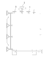
Fig. 1 is a structural representation of the present utility model.
Fig. 2 is a vertical view of the present utility model.
Fig. 3 is a left view of the present utility model.
Reference numeral:
1---insulation casing 2---tubular type shelf
3---drip pan 4---thermal source import
5---vacuum tube 6---vavuum pump
The outlet of 7---vacuum orifice 8---thermal source
9---revolving door 10---vacuum meter
11---thermometer 12---visor
13---handle 14---leg.
The specific embodiment
The utility model is described in further detail with embodiment below, is not practical range of the present utility model is limited to this.
As shown in Figure 1 to Figure 3, a kind of vacuum drier, comprise insulation casing 1, be provided with tubular type shelf 2 in the insulation casing 1, tubular type shelf 2 is provided with drip pan 3, described insulation casing 1 bottom is provided with thermal source import 4 and vacuum tube 5, these thermal source import 4 one ends are connected with evaporimeter, the other end is communicated with described tubular type shelf 2, vacuum tube 5 one ends connect vavuum pump 6, and insulation casing 1 top is provided with vacuum orifice 7 and thermal source outlet 8, and this thermal source outlet 8 is communicated with described tubular type shelf 2, at insulation casing 1 tubular type shelf 2 and drip pan 3 are set, by vavuum pump 6 insulation is evacuated in the casing 1, and the boiling point of material solution reduce under vacuum, and the driving force of heat transfer of evaporimeter is increased, therefore to certain heat output, can save the heat transfer area of evaporimeter, the heat loss of evaporimeter reduces, and is suitable for easy decomposition, polymerization and rotten heat sensitive material drying at high temperature, the utility model belongs to static vacuum drier, so the body of dried material can not damage.
The thermal source of evaporation operation can adopt low-pressure steam or waste hot steam in the utility model.
In the present embodiment, be provided with condenser in the described insulation casing 1, if adopt condenser, the evaporating solvent in the material can be reclaimed by condenser.
In the present embodiment, insulation casing 1 top also is provided with the hot water mouth of pipe and relief valve connection, and described insulation casing 1 bottom also is provided with sewage draining exit, condensate pipe, cooling water pipe, can play corresponding effect to the utility model by these pipelines.
In the present embodiment, one side of described insulation casing 1 is provided with a revolving door 9, this revolving door 9 is articulated in insulation casing 1, and described revolving door 9 is provided with vacuum meter 10 and thermometer 11, and vacuum meter 10 and thermometer 11 are convenient to correct the vacuumizing and dry effect in the insulation casing 1 of understanding.
In the present embodiment, described revolving door 9 also is provided with visor 12 and handle 13, and wherein, visor 12 can be seen vacuumizing and dry effect of insulation casing 1 material, and shakes hands 13 to be convenient to open insulation casing 1 and to place and take out material.
In the present embodiment, described insulation casing 1 bottom is provided with leg 14, and this leg 14 can be played a supporting role to the utility model integral body.
The above only is a better embodiment of the present utility model, so all equivalences of doing according to the described structure of the utility model patent claim, feature and principle change or modify, is included in the utility model patent claim.
Claims (8)
1. vacuum drier, it is characterized in that: comprise the insulation casing, be provided with the tubular type shelf in the insulation casing, the tubular type shelf is provided with drip pan, and described insulation lower box is provided with thermal source import and vacuum tube, and this thermal source import one end is connected with evaporimeter, the other end is communicated with described tubular type shelf, vacuum tube one end connects vavuum pump, and insulation casing top is provided with vacuum orifice and thermal source outlet, and this thermal source outlet is communicated with described tubular type shelf.
2. a kind of vacuum drier according to claim 1 is characterized in that: be provided with condenser in the described insulation casing.
3. a kind of vacuum drier according to claim 1 is characterized in that: described insulation casing top also is provided with the hot water mouth of pipe and relief valve connection.
4. a kind of vacuum drier according to claim 3 is characterized in that: described insulation lower box also is provided with sewage draining exit, condensate pipe, cooling water pipe.
5. a kind of vacuum drier according to claim 4 is characterized in that: a side of described insulation casing is provided with a revolving door, and this revolving door is articulated in the insulation casing.
6. a kind of vacuum drier according to claim 5 is characterized in that: described revolving door is provided with vacuum meter and thermometer.
7. a kind of vacuum drier according to claim 6 is characterized in that: described revolving door also is provided with visor and handle.
8. a kind of vacuum drier according to claim 7 is characterized in that: described insulation casing bottom is provided with leg.
Priority Applications (1)
| Application Number | Priority Date | Filing Date | Title |
|---|---|---|---|
| CN2011201309739U CN202032841U (en) | 2011-04-28 | 2011-04-28 | Vacuum dryer |
Applications Claiming Priority (1)
| Application Number | Priority Date | Filing Date | Title |
|---|---|---|---|
| CN2011201309739U CN202032841U (en) | 2011-04-28 | 2011-04-28 | Vacuum dryer |
Publications (1)
| Publication Number | Publication Date |
|---|---|
| CN202032841U true CN202032841U (en) | 2011-11-09 |
Family
ID=44895135
Family Applications (1)
| Application Number | Title | Priority Date | Filing Date |
|---|---|---|---|
| CN2011201309739U Expired - Fee Related CN202032841U (en) | 2011-04-28 | 2011-04-28 | Vacuum dryer |
Country Status (1)
| Country | Link |
|---|---|
| CN (1) | CN202032841U (en) |
Cited By (3)
| Publication number | Priority date | Publication date | Assignee | Title |
|---|---|---|---|---|
| CN102814269A (en) * | 2012-08-09 | 2012-12-12 | 常州市亚邦亚宇助剂有限公司 | Rapid drying device used for paint |
| CN103033030A (en) * | 2012-12-27 | 2013-04-10 | 雅化集团绵阳实业有限公司 | Automatic vacuum drier |
| CN112229156A (en) * | 2020-09-30 | 2021-01-15 | 南京中科药业有限公司 | Vacuum dryer and drying method thereof |
-
2011
- 2011-04-28 CN CN2011201309739U patent/CN202032841U/en not_active Expired - Fee Related
Cited By (5)
| Publication number | Priority date | Publication date | Assignee | Title |
|---|---|---|---|---|
| CN102814269A (en) * | 2012-08-09 | 2012-12-12 | 常州市亚邦亚宇助剂有限公司 | Rapid drying device used for paint |
| CN103033030A (en) * | 2012-12-27 | 2013-04-10 | 雅化集团绵阳实业有限公司 | Automatic vacuum drier |
| CN103033030B (en) * | 2012-12-27 | 2015-04-15 | 雅化集团绵阳实业有限公司 | Automatic vacuum drier |
| CN112229156A (en) * | 2020-09-30 | 2021-01-15 | 南京中科药业有限公司 | Vacuum dryer and drying method thereof |
| WO2022067881A1 (en) * | 2020-09-30 | 2022-04-07 | 南京中科药业有限公司 | Vacuum drier and drying method thereof |
Similar Documents
| Publication | Publication Date | Title |
|---|---|---|
| CN103461556A (en) | Production process for drying rosebuds at low temperature and recovering effective constituents and production equipment thereof | |
| CN206978637U (en) | A kind of congou tea Multi-stage heat circulation drier | |
| CN202032841U (en) | Vacuum dryer | |
| CN201267813Y (en) | Multifunctional cleaning, dewatering and drying machine | |
| CN207132677U (en) | A kind of negative pressure vacuumizes drying of wood processing unit (plant) | |
| CN202350444U (en) | Novel superconducting heat pump drying box | |
| CN105423731B (en) | Coal slime dewatering drying equipment and method | |
| CN209197350U (en) | It is a kind of for producing the heated-air circulation oven of condensed pill | |
| CN108088194A (en) | A kind of agricultural vacuum dewatering apparatus | |
| CN209204070U (en) | A kind of high-efficiency coating machine | |
| CN106016975A (en) | Box type drying device | |
| CN219223142U (en) | Food drying device | |
| CN202547286U (en) | Static drying oven for thermal sensitive materials | |
| CN206257918U (en) | A kind of tea drying device with rapid drying function | |
| CN101839620A (en) | Condensed mesh belt dryer | |
| CN206146130U (en) | Internal heating formula heat pump drying device | |
| CN108266977A (en) | It is a kind of that efficient food processing freeze-drying apparatus is lyophilized | |
| CN207180185U (en) | A kind of agricultural uses corn drying device | |
| CN208595759U (en) | A kind of pulse vacuum drying box | |
| CN201373657Y (en) | Condensing mesh-belt dryer | |
| CN207113467U (en) | A kind of medicine synthesis drying box | |
| CN207622391U (en) | Cold wall handles the drying cylinder of anti-coking | |
| CN204404705U (en) | Chinese medicine drying box equipment | |
| CN205482116U (en) | Negative pressure bin drying cabinet | |
| CN203024540U (en) | Heat pump negative pressure high-efficiency drier |
Legal Events
| Date | Code | Title | Description |
|---|---|---|---|
| C14 | Grant of patent or utility model | ||
| GR01 | Patent grant | ||
| CF01 | Termination of patent right due to non-payment of annual fee |
Granted publication date: 20111109 Termination date: 20160428 |