CN202031446U - Movable connection angle bracket - Google Patents
Movable connection angle bracket Download PDFInfo
- Publication number
- CN202031446U CN202031446U CN2011201197108U CN201120119710U CN202031446U CN 202031446 U CN202031446 U CN 202031446U CN 2011201197108 U CN2011201197108 U CN 2011201197108U CN 201120119710 U CN201120119710 U CN 201120119710U CN 202031446 U CN202031446 U CN 202031446U
- Authority
- CN
- China
- Prior art keywords
- connector
- main
- side connector
- sign indicating
- main connector
- Prior art date
- Legal status (The legal status is an assumption and is not a legal conclusion. Google has not performed a legal analysis and makes no representation as to the accuracy of the status listed.)
- Expired - Fee Related
Links
Images

Abstract
The utility model discloses a movable connection angle bracket, which comprises an angle bracket base for mounting a main window frame and a side window frame. The angle bracket base comprises a main connector and a side connector, an adjusting part for adjusting tension and a fastening part are arranged at the connection position of the main connector with the side connector, the main connector and the side connector are provided with a main mounting slot and a side mounting slot respectively, the adjusting part respectively penetrates through the main mounting slot, the main connector, the side connector and the slide mounting slot, the adjusting part and the fastening part are fittingly mounted together, the main connector and the side connector are provided with locking parts for locking the main window frame and the side window frame respectively, and thereby connection is firmer, mounting and demounting are simple, adjustment of tension of the main connector and the side connector is achieved and is flexible and convenient, size errors of the main window frame and the side window frame occurring in actual application are effectively overcome, service quality is ensured, unnecessary loss is avoided, service life is prolonged effectively, and manufacturing cost is reduced greatly.
Description
Technical field
The utility model patent relates to the joint angle sign indicating number of a kind of aluminium alloy doorframe and window frame fan group angle assembling usefulness, and particularly a kind of flexible connection angle sign indicating number is widely used in the linkage that all kinds of aluminium alloy doorframe and window frames are assembled.
Background technology
At present, most angle sign indicating number matrix is assembled into door-and window-frames with lateral frame and side stand group angle, angle sign indicating number matrix major part all is that metalwork or the working of plastics by an integral body constitutes, though the angle sign indicating number matrix of this structure is simple in structure, but it is complicated that the aluminium alloys window frame that causes corresponding lateral frame and side stand is made, thereby the operating efficiency of group angle assembling is reduced greatly, cause the cost height.
Yet, the angle sign indicating number matrix of the present aluminium alloys window frame fan group angle assembling that part is arranged on the market, this angle sign indicating number matrix adopting pressing connects, the angle existing problem of sign indicating number matrix that adopts pressing to connect is easy arrisdefect, and be difficult to behind the arrisdefect repair, thereby the assembler sets up the fixture that adopts wooden unit or plastics on the sign indicating number matrix of angle, fixture is arranged at the corner junction of angle sign indicating number matrix respectively, be provided with bolt in the corner junction, bolt is respectively by lateral frame, the aluminium gold gold window frame outer rim of side stand extends to angle sign indicating number matrix, and the locking that matches of bolt and fixture, and then make angle sign indicating number matrix be fixedly installed in lateral frame, side stand., this fixture is a wooden unit, is subjected to the influence of weather, occurs easily becoming damp, mouldy, the phenomenon of expanding with heat and contract with cold, and is difficult to fix, and has a strong impact on the quality of product, reduces application life; Perhaps, fixture is a working of plastics, in installation process or when using, overexerts and damages fixture, and decoding matrix junction is got loose, and have a strong impact on application life equally, and dismounting is extremely inconvenient, damages the quality of product easily.
And, in the practical set process, have on the size of junction of lateral frame, side stand and error occurs, but be difficult to regulate the scale error between lateral frame, the side stand, cause unnecessary loss.
Summary of the invention
The purpose of the utility model patent is to overcome the deficiencies in the prior art, provide a kind of simple in structure, adjust flexible, loading and unloading are easy, be connected firmly, and guarantee service property (quality), increase the service life and reduce the flexible connection angle sign indicating number of manufacturing cost.
The utility model purpose of the utility model patent is achieved in that a kind of flexible connection angle sign indicating number, comprise the angle sign indicating number matrix that is used to install on lateral frame and the side stand, it is characterized in that: described angle sign indicating number matrix comprises main connector and side connector, the junction of main connector and side connector is provided with regulating part and the fixture that is used to regulate elasticity, main connector and side connector are respectively equipped with main mounting groove and side mounting groove, regulating part passes main mounting groove respectively successively, main connector, side connector and side mounting groove, the installation that matches of regulating part and fixture, described main connector, the side connector is respectively equipped with the locking member that is used to lock lateral frame and side stand.
According to above-mentioned further qualification, described main connector and side connector are respectively equipped with through hole, by through hole regulating part and main connector, side connector are flexibly connected, and fixture is fixed on main connector or the side connector.
And described regulating part is a bolt, and fixture is a nut, and bolt is placed in main mounting groove, the corresponding through hole of nut and being placed on the side mounting groove, bolt pass through hole and with the adaptive installation of nut, regulate the elasticity between main connector and the side connector.
In addition, be made as sloping platform respectively on the lateral border of described main connector and side connector junction, sloping platform is provided with teeth, by teeth main connector closely is connected with the side connector.
Described main connector and side connector are connected to the L mold base.
Wherein, be respectively equipped with the installing hole and the groove of adaptive locking member on described main connector and the side connector, locking member is embedded in respectively on the groove of main connector and side connector, and locking member passes installing hole and lock onto on lateral frame and the side stand.
Also have, described locking member comprises block, elastic component and button, button is installed on the groove, and button extends on main connector and the side connector by installing hole, elastic component is placed in the button below, the elastic component other end is connected with block, and block and main connector, side connector flexibly connect, and block is installed on the groove.
According to above-mentioned further qualification, described elastic component is a spring, and button is provided with the locating hole of corresponding spring, the installation that matches of spring one end and locating hole, and the spring other end is connected with block.
Described main connector and side connector are respectively the aluminium alloys connector.
The utility model patent flexibly connects angle sign indicating number advantage and is following.
(1) by angle sign indicating number matrix is divided into main connector, side connector, set up main mounting groove and side mounting groove on main connector, the side connector, by regulating part, fixture and main connector, the side connector respective outer side edges that is placed in main mounting groove, side mounting groove, realize regulating the elasticity between main connector and the side connector, adjust flexible, effectively overcome the scale error that occurs in the practical application between lateral frame, the side stand, prevent unnecessary loss.
(2) owing to main connector, side connector are respectively equipped with locking member, when the knob of pressing locking member, main connector, side connector slide against respectively on lateral frame, the side stand, adopt the mode of clasp, knob is buckled on lateral frame, the side stand, and then makes main connector, side connector be fixedly installed in lateral frame or side stand respectively, when dismounting, press the button and make button to break away from lateral frame or the side stand, thereby the loading and unloading of realization the utility model patent are easy.
(3) teeth on the sloping platform that is respectively equipped with by main connector and side connector of the utility model patent cooperatively interact, and make main connector be connected and form the matrix of L type with the side connector, thereby it is more firm, tightr that the utility model patent is connected.
(4) main connector and side connector adopt the connector that the aluminium alloys manufacturing forms, and avoid being subjected to the improper use of weather effect or power and damage parts, guarantee service property (quality), effectively increase the service life.
(5) main connector and side connector are respectively equipped with main mounting groove, side mounting groove, groove, reduce raw-material use and guarantee the normal use of the utility model patent, reduce manufacturing cost greatly.
Description of drawings
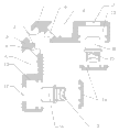
Accompanying drawing 1 is the structural representation of the utility model patent working example.
Accompanying drawing 2 is the structural representation of get loose in the utility model patent working example regulating part and fixture.
Accompanying drawing 3 is the decomposing schematic representation (removing regulating part and fixture) of the utility model patent working example.
Accompanying drawing 4 is the user mode figure of the utility model patent working example.
The specific embodiment
Below in conjunction with accompanying drawing the utility model patent is further described.
According to Fig. 1, Fig. 2, Fig. 3 and shown in Figure 4, the utility model patent is at being installed on lateral frame 7, on the alumium alloy door and window framework of side stand 8, described flexible connection angle sign indicating number, it comprises angle sign indicating number matrix, this angle sign indicating number matrix comprises main connector 1 and side connector 2, main connector 1 is provided with the regulating part 3 and fixture 4 that is used to regulate elasticity with the junction of side connector 2, main connector 1 is connected 2 and is respectively equipped with main mounting groove and 5 side mounting grooves 6 with side, regulating part 3 passes main mounting groove 5 respectively successively, main connector 1, side connector 2 and side mounting groove 6, and main connector 1 is respectively equipped with through hole 9 with side connector 2, make regulating part 3 and main connector 1 by through hole 9, side connector 2 flexibly connects, this regulating part 3 and fixture 4 match install after, main connector 1 closely is connected with side connector 2.And owing to be made as sloping platform respectively on the lateral border of main connector 1, side connector 2 junctions, sloping platform is provided with teeth 11, be meshing with each other by teeth 11, and main connector 1 is connected to the L mold base with side connector 2, thereby makes utility model easy to use, connects more firm tightr again.
In actual applications, this regulating part 3 is that bolt, fixture 4 is nut, and bolt is installed on main mounting groove 5, the corresponding through hole 9 of nut and being installed on the side mounting groove 6, bolt pass through hole 9 and with the adaptive installation of nut.If in the practical set process, when the scale error of junction of lateral frame 7, side stand 8 occurring, the main connector 2, the side connector 3 that are installed on respectively on lateral frame 7, the side stand 8 can be by regulating the elasticity between the bolts and nuts, and then allocate distance between main connector 2 and the side connector 3, avoid damaging parts or abandoning to parts because of scale error, cause unnecessary loss, thereby realize easy to adjust flexible again.
Moreover, the main connector 1 of the utility model patent, side connector 2 are respectively equipped with the locking member that is used to lock lateral frame 7 and side stand 8, and also be respectively equipped with the installing hole 12 and groove 13 of adaptive locking member on main connector 1 and the side connector 2, locking member is embedded in respectively on the groove 13 of main connector 1 and side connector 2, and locking member passes installing hole 12 and lock onto on lateral frame 7 and the side stand 8.Wherein, locking member comprises block 14, elastic component 15 and button 16, button 16 is installed on the groove 13, and button 16 extends on main connector 1 and the side connector 2 by installing hole 12, elastic component 15 is placed in button 16 belows, elastic component 15 other ends are connected with block 14, and block 14 flexibly connects with main connector 1, side connector 2, and block 14 is installed on the groove 13.This elastic component 15 is a spring, and button 16 is provided with the locating hole 10 of corresponding spring, makes spring one end be fixedly installed in button 16 belows by locating hole 10, and the spring other end is connected with block 14.
Promptly, in assembling process, press the button 16 and compression elastic piece 15, main connector 1, side connector 2 are slided along the inner chamber of adaptive lateral frame 7 or side stand 8 respectively, when reaching assigned address, knob 16 resets under the effect of elastic component 15 and is buckled on lateral frame 7 or the side stand 8, these elastic component 15 other end roof pressures block 14, block 14 fixedly is embedded on the groove 13 and block 14 is close on lateral frame 7 or the side stand 8, thereby makes main connector 1, side connector 2 be fixedly installed in lateral frame 7 or side stand 8 respectively; In like manner, press the button 16 and compression elastic piece 15, make button 16 break away from lateral frame 7 or side stands 8, and then main connector 1, side connector 2 are taken apart from lateral frame 7 or side stand 8 respectively, realize that the loading and unloading of the utility model patent are easy, increase work efficiency greatly and reduce manufacturing cost.
And, the main connector 1 of the utility model patent is respectively the aluminium alloys connector with side connector 2, replaces the existing angle sign indicating number connector that adopts wooden unit or working of plastics, avoids being subjected to the improper use of weather effect or power and damages parts, guarantee service property (quality), effectively increase the service life.
Claims (9)
1. one kind flexibly connects the angle sign indicating number, comprise the angle sign indicating number matrix that is used to be installed on lateral frame (7) and the side stand (8), it is characterized in that: described angle sign indicating number matrix comprises main connector (1) and side connector (2), main connector (1) is provided with the regulating part (3) and fixture (4) that is used to regulate elasticity with the junction of side connector (2), main connector (1) is respectively equipped with main mounting groove (5) and side mounting groove (6) with side connector (2), regulating part (3) passes main mounting groove (5) respectively successively, main connector (1), side connector (2) and side mounting groove (6), the installation that matches of regulating part (3) and fixture (4), described main connector (1), side connector (2) is respectively equipped with the locking member that is used to lock lateral frame (7) and side stand (8).
2. according to the described flexible connection of claim 1 angle sign indicating number, it is characterized in that: described main connector (1) is respectively equipped with through hole (9) with side connector (2), by through hole (9) regulating part (3) and main connector (1), side connector (2) are flexibly connected, fixture (4) is fixed on main connector (1) or the side connector (2).
3. according to the described flexible connection of claim 2 angle sign indicating number, it is characterized in that: described regulating part (3) is a bolt, fixture (4) is a nut, bolt is placed in main mounting groove (5), the corresponding through hole (9) of nut and being placed on the side mounting groove (6), bolt pass through hole (9) and with the adaptive installation of nut, regulate the elasticity between main connector (1) and the side connector (2).
4. according to the described flexible connection of claim 3 angle sign indicating number, it is characterized in that: be made as sloping platform respectively on the lateral border of described main connector (1) and side connector (2) junction, sloping platform is provided with teeth (11), by teeth (11) main connector (1) closely is connected with side connector (2).
5. according to the described flexible connection of claim 3 angle sign indicating number, it is characterized in that: described main connector (1) is connected to the L mold base with side connector (2).
6. according to the described flexible connection of claim 1 angle sign indicating number, it is characterized in that: the installing hole (12) and groove (13) that are respectively equipped with adaptive locking member on described main connector (1) and the side connector (2), locking member is embedded in respectively on the groove (13) of main connector (1) and side connector (2), and locking member passes installing hole (12) and lock onto on main beam (7) and the side stand (8).
7. according to the described flexible connection of claim 6 angle sign indicating number, it is characterized in that: described locking member comprises block (14), elastic component (15) and button (16), button (16) is installed on the groove (13), and button (16) extends on main connector (1) and the side connector (2) by installing hole (12), elastic component (15) is placed in button (16) below, elastic component (15) other end is connected with block (14), block (14) flexibly connects with main connector (1), side connector (2), and block (14) is installed on the groove (13).
8. according to the described flexible connection of claim 7 angle sign indicating number, it is characterized in that: described elastic component (15) is a spring, button (16) is provided with the locating hole (10) of corresponding spring, the installation that matches of spring one end and locating hole (10), and the spring other end is connected with block (14).
9. according to claim 5 or 7 described flexible connection angle sign indicating numbers, it is characterized in that: described main connector (1) is respectively the aluminium alloys connector with side connector (2).
Priority Applications (1)
| Application Number | Priority Date | Filing Date | Title |
|---|---|---|---|
| CN2011201197108U CN202031446U (en) | 2011-04-21 | 2011-04-21 | Movable connection angle bracket |
Applications Claiming Priority (1)
| Application Number | Priority Date | Filing Date | Title |
|---|---|---|---|
| CN2011201197108U CN202031446U (en) | 2011-04-21 | 2011-04-21 | Movable connection angle bracket |
Publications (1)
| Publication Number | Publication Date |
|---|---|
| CN202031446U true CN202031446U (en) | 2011-11-09 |
Family
ID=44893748
Family Applications (1)
| Application Number | Title | Priority Date | Filing Date |
|---|---|---|---|
| CN2011201197108U Expired - Fee Related CN202031446U (en) | 2011-04-21 | 2011-04-21 | Movable connection angle bracket |
Country Status (1)
| Country | Link |
|---|---|
| CN (1) | CN202031446U (en) |
Cited By (11)
| Publication number | Priority date | Publication date | Assignee | Title |
|---|---|---|---|---|
| CN102182386A (en) * | 2011-04-21 | 2011-09-14 | 佛山市顺德区兴益康金属科技有限公司 | Corner connector for movable connection |
| CN103924870A (en) * | 2014-04-23 | 2014-07-16 | 浙江元森态家具有限公司 | Method for mounting wood-plastic house aluminum alloy door frame |
| CN103924670A (en) * | 2014-04-23 | 2014-07-16 | 浙江元森态家具有限公司 | Environment-friendly and wood-plastic house |
| CN103938721A (en) * | 2014-04-23 | 2014-07-23 | 浙江元森态家具有限公司 | Plastic wood house assembling structure |
| CN103938879A (en) * | 2014-04-23 | 2014-07-23 | 浙江元森态家具有限公司 | Wood plastic house assembling method |
| CN105275342A (en) * | 2015-11-12 | 2016-01-27 | 万国富 | Fully hidden type corner connector and ecological door frame provided with same |
| CN105442710A (en) * | 2015-08-27 | 2016-03-30 | 杭州康利达卫浴有限公司 | Corner connecting piece |
| CN105822195A (en) * | 2016-04-29 | 2016-08-03 | 山东建筑大学 | Expandable door and window corner connector |
| CN107223002A (en) * | 2017-06-30 | 2017-09-29 | 苏州广能电子科技有限公司 | Framework connection corner fittings |
| CN107905690A (en) * | 2017-12-21 | 2018-04-13 | 广东亿合门窗科技有限公司 | Corner brace |
| CN108590458A (en) * | 2018-04-17 | 2018-09-28 | 中亿丰建设集团股份有限公司 | A kind of split type connecting corner yard of doorframe |
-
2011
- 2011-04-21 CN CN2011201197108U patent/CN202031446U/en not_active Expired - Fee Related
Cited By (13)
| Publication number | Priority date | Publication date | Assignee | Title |
|---|---|---|---|---|
| CN102182386A (en) * | 2011-04-21 | 2011-09-14 | 佛山市顺德区兴益康金属科技有限公司 | Corner connector for movable connection |
| CN103924870A (en) * | 2014-04-23 | 2014-07-16 | 浙江元森态家具有限公司 | Method for mounting wood-plastic house aluminum alloy door frame |
| CN103924670A (en) * | 2014-04-23 | 2014-07-16 | 浙江元森态家具有限公司 | Environment-friendly and wood-plastic house |
| CN103938721A (en) * | 2014-04-23 | 2014-07-23 | 浙江元森态家具有限公司 | Plastic wood house assembling structure |
| CN103938879A (en) * | 2014-04-23 | 2014-07-23 | 浙江元森态家具有限公司 | Wood plastic house assembling method |
| CN105442710A (en) * | 2015-08-27 | 2016-03-30 | 杭州康利达卫浴有限公司 | Corner connecting piece |
| CN105442710B (en) * | 2015-08-27 | 2018-06-05 | 杭州康利达卫浴有限公司 | A kind of Corner Link |
| CN105275342A (en) * | 2015-11-12 | 2016-01-27 | 万国富 | Fully hidden type corner connector and ecological door frame provided with same |
| CN105275342B (en) * | 2015-11-12 | 2017-03-15 | 万国富 | Full angle of repose code and apply its ecological doorframe |
| CN105822195A (en) * | 2016-04-29 | 2016-08-03 | 山东建筑大学 | Expandable door and window corner connector |
| CN107223002A (en) * | 2017-06-30 | 2017-09-29 | 苏州广能电子科技有限公司 | Framework connection corner fittings |
| CN107905690A (en) * | 2017-12-21 | 2018-04-13 | 广东亿合门窗科技有限公司 | Corner brace |
| CN108590458A (en) * | 2018-04-17 | 2018-09-28 | 中亿丰建设集团股份有限公司 | A kind of split type connecting corner yard of doorframe |
Similar Documents
| Publication | Publication Date | Title |
|---|---|---|
| CN202031446U (en) | Movable connection angle bracket | |
| CN102182386A (en) | Corner connector for movable connection | |
| CN101498399B (en) | Section bar connection device and section bar apparatus with the same | |
| CN209194799U (en) | A kind of wind-proof, shock-reducing type glass curtain wallboard | |
| CN202299039U (en) | Connecting device of steel keel frame hidden-frame glass curtain wall | |
| CN210003617U (en) | Assembling structure of aluminium section bar board and kinds of combined cabinet | |
| CN210179152U (en) | Rectangular metal compensator | |
| CN201258671Y (en) | Assembly steel door case | |
| CN201373608Y (en) | Connecting device used between unit bodies in large solar thermal collector | |
| CN210518200U (en) | Small frame structure for double-glass assembly | |
| CN211447333U (en) | Waterproof building wall | |
| CN219240883U (en) | Connection structure of metal structure | |
| CN201991080U (en) | Connecting component for sectional bars | |
| CN204531821U (en) | A kind of folding door top sheave | |
| CN216390891U (en) | Novel photovoltaic module frame and framework | |
| CN218437791U (en) | Steel structure box type combination column | |
| CN204226447U (en) | For the support body in drive axle support | |
| CN210532642U (en) | Fixing assembly of aluminum alloy air conditioner grille | |
| CN217106781U (en) | Nailing quick assembly disassembly's screen window exempts from | |
| CN203570901U (en) | Shackle type automobile leaf spring easy to dismount | |
| CN215330750U (en) | Aluminum plate curtain wall with high air tightness | |
| CN203524582U (en) | Vacuum cleaner ground brush | |
| CN209891832U (en) | Fixing structure of handle and driver | |
| CN2919533Y (en) | Frame sliding chute for packaging solar battery assembly | |
| CN207087746U (en) | Ears locked spacer fixation kit |
Legal Events
| Date | Code | Title | Description |
|---|---|---|---|
| C14 | Grant of patent or utility model | ||
| GR01 | Patent grant | ||
| CF01 | Termination of patent right due to non-payment of annual fee |
Granted publication date: 20111109 Termination date: 20190421 |
|
| CF01 | Termination of patent right due to non-payment of annual fee |