CN202020497U - Spring grasping forceps - Google Patents
Spring grasping forceps Download PDFInfo
- Publication number
- CN202020497U CN202020497U CN2011200693562U CN201120069356U CN202020497U CN 202020497 U CN202020497 U CN 202020497U CN 2011200693562 U CN2011200693562 U CN 2011200693562U CN 201120069356 U CN201120069356 U CN 201120069356U CN 202020497 U CN202020497 U CN 202020497U
- Authority
- CN
- China
- Prior art keywords
- spring
- pull rod
- forceps
- seat
- handle
- Prior art date
- Legal status (The legal status is an assumption and is not a legal conclusion. Google has not performed a legal analysis and makes no representation as to the accuracy of the status listed.)
- Expired - Fee Related
Links
Images

Abstract
The utility model relates to a pair of spring grasping forceps which is specially used for grasping tiny organs in a human body through longitudinal traction and extrication from front view in a human laparoscopic surgery, and belongs to the technical field of medical equipment. The pair of spring grasping forceps consists of a spring handle, a forceps seat, a forceps rod, a pull rod, a pull rod seat, a pull rod slot, forceps clips, spring pieces, non-invasive dental patterns, a connecting seat and screws, wherein the connecting seat is sheathed into one end of the spring handle, the pull rod seat is provided with the pull rod slot, the other end of the spring handle is fixedly welded with the pull rod seat, ends of the two spring pieces are fixedly welded on the pull rod, other ends of the two spring pieces are fixedly welded with the forceps clips, the two forceps clips are respectively provided with the non-invasive dental patterns which are tallied with one another when the non-invasive dental patterns are clamped, the forceps seat is fixedly welded with the forceps rod, and the pull rod penetrates through the forceps rod and the connecting seat to be sheathed in the pull rod slot and fixedly connected by using the screws.
Description
Technical field
This utility model relates to a kind of peritoneoscope human body operation, is exclusively used in the inside of human body miniorgan and grasps the free direct-view of longitudinal traction spring nipper, belongs to technical field of medical instruments.
Background technology
In the human abdominal cavity videoendoscopic surgery, it is free to grasp longitudinal traction to the miniorgan of lesions position periphery, prior art is with common nipper, the miniorgan who carries out people's internal lesions position periphery grasps longitudinal traction and dissociates, its defective is: the common sharp bodily form of hoe scaler pliers head clip tooth is big, can damage the miniorgan in the operation traction with in dissociating, cause the secondary wound, not satisfy ideal surgical effect.
Summary of the invention
Technical problem to be solved in the utility model provides a kind of reasonable in design, can not damage the miniorgan, performs the operation and use spring nipper convenient, that extracting is effective, safe.
It is this spring nipper that this utility model solves the problems of the technologies described above the technical scheme that is adopted, its construction features is: be made up of spring handle, pincers seat, claw beam, pull bar, draw-bar seat, pull rod slot, clamp, shell fragment, noinvasive flute profile, Connection Block, screw, described Connection Block is inserted in an end of spring handle, draw-bar seat has pull rod slot, and the spring handle other end and draw-bar seat welding are fixing; Two shell fragment one ends are weldingly fixed on the pull bar, and the other end and clamp welding are fixing, and two clamps have the noinvasive flute profile, coincide mutually when the noinvasive flute profile clamps, and the pincers seat is fixing with the claw beam welding; Pull bar is through in the claw beam, and described pull bar passes Connection Block and is inserted in pull rod slot and is connected and fixed with screw.
Spring handle described in the utility model is to make of spring steel.
This utility model is compared with prior art and is had the following advantages and effect: the structural design pincers type bodily form little (claw beam is the thickest to have only 3 millimeters), clamp is provided with the noinvasive flute profile, the jaw arrangement design pincers type bodily form is little, applying flexible, grasp the miniorgan undergo surgery traction and free in, can never damage the miniorgan, convenient, effective, the safety of extracting that operation is used.Itself has elasticity handle, drives the work of rubber-like clamp, clamps firmly can arbitrarily not come off, and simplicity of design is reasonable, applying flexible, safety easy to use.
Description of drawings
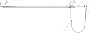
Fig. 1 is a structural representation of the present utility model.
Fig. 2 is the structural representation of this utility model head.
Label declaration: spring handle 1, pincers seat 2, claw beam 3, pull bar 4, draw-bar seat 5, pull rod slot 6, clamp 7, shell fragment 8, noinvasive flute profile 9, Connection Block 10, screw 11.
The specific embodiment
Below in conjunction with embodiment this utility model is described in further detail, following examples are to explanation of the present utility model and this utility model is not limited to following examples.
Embodiment 1: as shown in Figure 1, 2, present embodiment is made up of spring handle 1, pincers seat 2, claw beam 3, pull bar 4, draw-bar seat 5, pull rod slot 6, clamp 7, shell fragment 8, noinvasive flute profile 9, Connection Block 10, screw 11.
Annexation of the present utility model is: Connection Block 10 is inserted in an end of spring handle 1, and draw-bar seat 5 has pull rod slot 6, and spring handle 1 other end and draw-bar seat 5 welding are fixing; Two shell fragments 8 have elasticity, and an end is weldingly fixed on the pull bar 4, and the other end and clamp 7 welding are fixing, clamp 7 is opened naturally have elasticity; Two clamps 7 have noinvasive flute profile 9, coincide mutually when noinvasive flute profile 9 clamps.Pincers seat 2 is fixing with claw beam 3 welding; Pull bar 4 penetrates claw beam 3, passes Connection Block 10, is inserted in pull rod slot 6 usefulness screws 11 and is connected and fixed.
The spring nipper of this utility model design, spring handle 1 are that spring steel is made, and spring handle 1 itself has elasticity, drive 7 work of rubber-like clamp, clamp firmly can arbitrarily not come off, and simplicity of design is reasonable, applying flexible, safety easy to use.
The spring nipper of this utility model design, the art designs of clamp 7 has or not gear-shaping type 9, grasps in the free operation of longitudinal traction lesions position periphery miniorgan, and it is effective that the noinvasive flute profile 9 of clamp 7 grasps the miniorgan, can never damage the miniorgan; The clamp 7 structural design pincers type bodily forms are little, applying flexible.
The spring nipper of this utility model design removes and installs conveniently, and closure is good, and metal material is made, and sterilization can be used liquid disinfectant, also can use high-temperature sterilization.
In addition, need to prove, the specific embodiment described in this description, its zero, the shape of parts, institute's title of being named etc. can be different.Allly conceive equivalence or the simple change that described structure, feature and principle are done, be included in the protection domain of this utility model patent according to this utility model patent.This utility model person of ordinary skill in the field can make various modifications or replenishes or adopt similar mode to substitute described specific embodiment; only otherwise depart from structure of the present utility model or surmount the defined scope of these claims, all should belong to protection domain of the present utility model.
Claims (2)
1. spring nipper, it is characterized in that: form by spring handle, pincers seat, claw beam, pull bar, draw-bar seat, pull rod slot, clamp, shell fragment, noinvasive flute profile, Connection Block, screw, described Connection Block is inserted in an end of spring handle, draw-bar seat has pull rod slot, and the spring handle other end and draw-bar seat welding are fixing; Two shell fragment one ends are weldingly fixed on the pull bar, and the other end and clamp welding are fixing, and two clamps have the noinvasive flute profile, coincide mutually when the noinvasive flute profile clamps, and the pincers seat is fixing with the claw beam welding; Pull bar is through in the claw beam, and described pull bar passes Connection Block and is inserted in pull rod slot and is connected and fixed with screw.
2. spring nipper according to claim 1 is characterized in that: described spring handle is to make of spring steel.
Priority Applications (1)
| Application Number | Priority Date | Filing Date | Title |
|---|---|---|---|
| CN2011200693562U CN202020497U (en) | 2011-03-16 | 2011-03-16 | Spring grasping forceps |
Applications Claiming Priority (1)
| Application Number | Priority Date | Filing Date | Title |
|---|---|---|---|
| CN2011200693562U CN202020497U (en) | 2011-03-16 | 2011-03-16 | Spring grasping forceps |
Publications (1)
| Publication Number | Publication Date |
|---|---|
| CN202020497U true CN202020497U (en) | 2011-11-02 |
Family
ID=44845467
Family Applications (1)
| Application Number | Title | Priority Date | Filing Date |
|---|---|---|---|
| CN2011200693562U Expired - Fee Related CN202020497U (en) | 2011-03-16 | 2011-03-16 | Spring grasping forceps |
Country Status (1)
| Country | Link |
|---|---|
| CN (1) | CN202020497U (en) |
Cited By (1)
| Publication number | Priority date | Publication date | Assignee | Title |
|---|---|---|---|---|
| CN109770974A (en) * | 2019-03-13 | 2019-05-21 | 中山大学附属第一医院 | A kind of thymoma Minimally Invasive Surgery lobe of the lung radical occlusion device |
-
2011
- 2011-03-16 CN CN2011200693562U patent/CN202020497U/en not_active Expired - Fee Related
Cited By (1)
| Publication number | Priority date | Publication date | Assignee | Title |
|---|---|---|---|---|
| CN109770974A (en) * | 2019-03-13 | 2019-05-21 | 中山大学附属第一医院 | A kind of thymoma Minimally Invasive Surgery lobe of the lung radical occlusion device |
Similar Documents
| Publication | Publication Date | Title |
|---|---|---|
| CN202020497U (en) | Spring grasping forceps | |
| CN201642206U (en) | Visualized spring grabbing forceps | |
| CN202497194U (en) | Cholangiography forceps | |
| CN201290714Y (en) | Direct-view micro-wound needle holder | |
| CN203252679U (en) | Needle carrier | |
| CN201469342U (en) | Right-angle titanium clamp | |
| CN107007312A (en) | Multi-functional needle holder | |
| CN201290728Y (en) | Direct-view micro-wound no-wound gripping tongs | |
| CN203252696U (en) | Small incision operation grasping forceps | |
| CN202020494U (en) | Oval grasping forceps | |
| CN201015594Y (en) | Small lancing closing clamp | |
| CN202020469U (en) | Traction tongs | |
| CN202020467U (en) | Pulling tongs | |
| CN201631308U (en) | Direct-vision pulling and floating forceps | |
| CN202020496U (en) | O-shaped grasping forceps | |
| CN201683995U (en) | Soft foreign forceps | |
| CN202069625U (en) | Grasping forceps for direct-vision body operation | |
| CN202665637U (en) | Laparoscope eccentric clamp | |
| CN202036280U (en) | Thoracic cavity pulmonary lobe clamp | |
| CN202036312U (en) | Large-scale separating clamp | |
| CN201642208U (en) | Direct-vision five-blade forceps | |
| CN201631310U (en) | Direct vision canine tooth grasping forceps | |
| CN201631347U (en) | Hard foreign body forceps | |
| CN201350117Y (en) | Electriccoagulation straight forceps used for human face-lifting | |
| CN202020498U (en) | Round-headed grasping forceps |
Legal Events
| Date | Code | Title | Description |
|---|---|---|---|
| C14 | Grant of patent or utility model | ||
| GR01 | Patent grant | ||
| C17 | Cessation of patent right | ||
| CF01 | Termination of patent right due to non-payment of annual fee |
Granted publication date: 20111102 Termination date: 20120316 |