CN202009809U - Portable folding table - Google Patents
Portable folding table Download PDFInfo
- Publication number
- CN202009809U CN202009809U CN2011201215290U CN201120121529U CN202009809U CN 202009809 U CN202009809 U CN 202009809U CN 2011201215290 U CN2011201215290 U CN 2011201215290U CN 201120121529 U CN201120121529 U CN 201120121529U CN 202009809 U CN202009809 U CN 202009809U
- Authority
- CN
- China
- Prior art keywords
- type
- desktop
- leg
- section
- portable folding
- Prior art date
- Legal status (The legal status is an assumption and is not a legal conclusion. Google has not performed a legal analysis and makes no representation as to the accuracy of the status listed.)
- Expired - Fee Related
Links
Images




Landscapes
- Tables And Desks Characterized By Structural Shape (AREA)
Abstract
The utility model discloses a portable folding table, which comprises a tabletop plate and table legs. The table legs include two U-shaped legs separately arranged on two sides of the bottom of the tabletop plate; both the top ends of two side bar sections of each U-shaped leg are provided with an L-shaped upper support for supporting the bottom of the tabletop plate; each L-shaped upper support includes a support section and a rotary shaft section; each support section is connected with the corresponding side bar section of the corresponding U-shaped leg; each rotary shaft section is parallel to a cross bar section of the corresponding U-shaped leg; two arched sleeves for inserting the rotary shaft sections are symmetrically mounted on both of two sides of the bottom of the tabletop plate; and the two U-shaped legs are supported at the bottom of the tabletop plate by outwardly rotating around the arched sleeves or folded at the bottom of the tabletop plate by inwardly rotating around the arched sleeves through the respective rotary shaft sections. The portable folding table is capable of realizing mechanical production, stable production quality and high production efficiency, and has the advantages of stability and firmness in support, foldability of the table legs, rapidness in detachment and installation, and convenience for carrying and using.
Description
Technical field
The utility model relates to the furniture technology, collapsible, the portable folding table of particularly a kind of table leg.
Background technology
At present, seldom finding to can be used on the bed on the market or the small wood tables furniture of party occasion such as couch, although there is only a few enterprise to develop bed table, its shortcoming is or tables' heaviness very; Or structure is not removable, is not easy to move and place.Therefore developing a kind of light, collapsible, small-sized fast and easily desk of dismounting is a very significant thing.
The utility model content
Technical problem to be solved in the utility model is: at the deficiencies in the prior art, provide a kind of and realize that mechanization production, the quality of production are stablized, production efficiency is high, supporting ﹠ stablizing is firm, table leg is collapsible, dismounting is quick, portably use portable folding table easily.
For solving the problems of the technologies described above, the utility model by the following technical solutions:
A kind of portable folding table, comprise desktop and table leg, described table leg comprises two U type legs that are divided into the desktop two bottom sides, two side lever section tops of described U type leg are equipped with the L type upper support portion that is used to be supported in the desktop bottom, described L type upper support portion comprises the supporting section that links to each other with U type leg side lever section and is parallel to the rotating shaft section of U type leg rail segment, described desktop two bottom sides is two arch sleeve pipes that plug described rotating shaft section of symmetry installing all, two U type legs rotating shaft section by separately around the outside rotational support of arch sleeve pipe in the desktop bottom or inwardly rotate and be folded to the desktop bottom.
As further improvement of the utility model, described desktop bottom symmetry is equiped with four draw-in grooves that are used to hold each supporting section.Described draw-in groove can be L type draw-in groove, the opening of L type draw-in groove and corresponding described rotating shaft section be inserted in the arch sleeve pipe to plug direction relative.
Further improve as of the present utility model, described desktop bottom symmetry is equiped with four sheet Connection Blocks, and described arch sleeve pipe and L type draw-in groove all are installed in the desktop bottom by corresponding Connection Block.
Described L type upper support portion for by the side lever section top of U type leg by 90 ° of integrative-structures that form of secondary bending.
Described U type leg forms for being bent by metal round rod, and the diameter of described metal round rod is not less than 5mm.
Compared with prior art, advantage of the present utility model is:
Portable folding table of the present utility model, by the arch sleeve pipe being set in the desktop bottom, two side lever section tops of U type leg are provided with supporting section and the rotating shaft section that is the L type, each rotating shaft section is inserted in the corresponding arch sleeve pipe, U type leg can be by separately the rotating shaft section around the outside rotational support of arch sleeve pipe in the desktop bottom or inwardly rotate and be folded to the desktop bottom, simple in structure, easy to install and use.Arch sleeve pipe wherein can be in the bottom of factory's predetermined fixed at desktop, when installing, the consumer do not need to use any specific purpose tool, only need U type leg is firmly strutted, and each rotating shaft section is inserted in the corresponding arch sleeve pipe, utilize the elastic force of U type leg self can be arranged in the arch sleeve pipe, supporting section wherein and rotating shaft section are served as support rail, therefore need not other support rail and tongue-and-groove and engage, supporting ﹠ stablizing, in light weight.When not needing to use desk, as long as two U type legs are inwardly rotated about 97 °, table leg promptly may be folded in the desktop bottom, and space required when storing or carrying is minimum, can hang on metope, is convenient to especially carry.
Portable folding table of the present utility model, draw-in groove also can be installed in the desktop bottom, and draw-in groove can be L type draw-in groove, fixing table leg when using desk makes table leg can not rotate supporting ﹠ stablizing, as long as U type leg is strutted, make its supporting section leave L type draw-in groove, i.e. rotatable folding table leg when not using.
Portable folding table of the present utility model can be fixed in the arch sleeve pipe and the L type draw-in groove of relevant position with on a connecting seat earlier, again Connection Block is fixed in the desktop bottom in factory in advance, and more convenient and quicker is installed.
The L type upper support portion on U type leg top for by the side lever section top of U type leg by 90 ° of integrative-structures that form of secondary bending, process simple and convenient.
Description of drawings
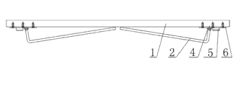
Fig. 1 is a main TV structure schematic diagram of the present utility model;
Fig. 2 is the structural representation of looking up of the present utility model;
Fig. 3 is a side-looking structural representation of the present utility model;
Fig. 4 is the structural representation after the utility model table leg folds;
Fig. 5 is the syndeton schematic diagram of Connection Block and arch sleeve pipe and draw-in groove in the utility model;
Fig. 6 be among Fig. 2 A to local structure for amplifying schematic diagram; (having removed U type leg and desktop)
Fig. 7 be among Fig. 2 B to local structure for amplifying schematic diagram; (having removed U type leg and desktop)
Fig. 8 be among Fig. 2 C to local structure for amplifying schematic diagram; (having removed U type leg and desktop)
Marginal data:
1, desktop; 2, table leg; 3, L type upper support portion; 31, supporting section; 32, rotating shaft section; 4, arch sleeve pipe; 5, L type draw-in groove; 6, Connection Block; 7, screw.
The specific embodiment
Below in conjunction with specific embodiment and Figure of description the utility model is further described.
As Fig. 1~shown in Figure 8, portable folding table of the present utility model comprises desktop 1 and table leg 2, and table leg 2 comprises two U type legs, and two U type legs are divided into the two bottom sides of desktop 1.Two side lever section tops of U type leg are equipped with L type upper support portion 3, L type upper support portion 3 can fit with desktop 1 bottom and support, L type upper support portion 3 comprises supporting section 31 and rotating shaft section 32, and supporting section 31 links to each other with the side lever section of U type leg, and rotating shaft section 32 is parallel to the rail segment of U type leg.Desktop 1 two bottom sides is two arch sleeve pipes 4 of symmetry installing all, four arch sleeve pipes 4 are arranged in parallel, wherein, two arch sleeve pipe 4 coaxial lines of homonymy are arranged, two U type legs are inserted in the corresponding arch sleeve pipe 4 by rotating shaft section 32 separately, can be around arch sleeve pipe 4 outside rotational support in desktop 1 bottom or inwardly rotate and be folded to desktop 1 bottom.Arch sleeve pipe 4 can be in the bottom of factory's predetermined fixed at desktop 1, when installing, the consumer do not need to use any specific purpose tool, only need U type leg is firmly strutted, each rotating shaft section 32 is inserted in the arch sleeve pipe 4, utilizes the elastic card of U type leg to be located at arch sleeve pipe 4 interior getting final product, its installation is simple, easy to use, wherein supporting section 31 and rotating shaft section 32 are served as support rail, therefore need not other support rail and tongue-and-groove and engage, simple in structure and supporting ﹠ stablizing, in light weight.When not needing to use desk, as long as two U type legs are inwardly rotated, promptly may be folded in desktop 1 bottom, space required when storing or carrying is minimum, can hang on metope, is convenient to especially carry.
In the present embodiment, be preferably vertical connection between the side lever section of supporting section 31, rotating shaft section 32 and U type leg, be the plane formed of supporting section 31 and rotating shaft section 32 perpendicular to the side lever section of U type leg and the plane at rail segment place, this structure makes the support of table leg more reliable and more stable.Supporting section 31 and rotating shaft section 32 are preferably side lever section top by U type leg by 90 ° of integrative-structures that form of secondary bending, and it is simple in structure, and processing and manufacturing is easy, and bonding strength also can be guaranteed.Among other embodiment, supporting section 31 also can be non-perpendicular the connection with the side lever section of rotating shaft section 32 and U type leg, as long as guarantee between the rail segment of rotating shaft section 32 and U type leg parallel.U type leg forms for being bent by metal round rod, and the diameter of metal round rod is not less than 5mm, can guarantee its support strength.
In the present embodiment, desktop 1 is that rectangle (also can be other shapes, as square, circle and ellipse etc.), its bottom is four L type draw-in grooves 5 of symmetry installing also, be used to hold each supporting section 31 with fixing table leg 2, make its support more reliable and more stable, the opening of L type draw-in groove 5 and corresponding rotating shaft section 32 be inserted in arch sleeve pipe 4 to plug direction relative.Desktop 1 is preferably solid wood plate or various wood-based plate, as particieboard, medium density fibre board (MDF), glued board, novel wooden composite etc., also can be plastics, and the thickness of desktop 1 is not less than 12mm.
The utility model is further at four Connection Blocks 6 of the bottom of desktop 1 symmetry installing, an arch sleeve pipe 4 and a L type draw-in groove 5 are all installed in every Connection Block 6 bottoms, arch sleeve pipe 4 and L type draw-in groove 5 are installed in desktop 1 bottom by corresponding Connection Block 6, and arch sleeve pipe 4 on adjacent two Connection Blocks 6 and L type draw-in groove 5 be symmetric arrangement each other.Connection Block 6 pref. cylindrical disc structures can also be the disc structure of other shapes.Connection Block 6, arch sleeve pipe 4 and L type draw-in groove 5 can be in the bottom of factory's predetermined fixed at desktop 1 after being assembled into integral body, its installation and use more convenient.In the present embodiment, the diameter of cylindrical disc is preferably 60mm, and thick is 2mm, is evenly equipped with 4 ladder holes on the cylindrical disc, and is fixed on the bottom surface of desktop 1 by screw 7.Ladder hole is preferably dimensioned to be: diameter 6mm * dark 1.5mm and diameter are 4.5mm * dark 0.5mm.
When table leg 2 is installed, placements that earlier desktop 1 turned over, firmly the table leg 2 with the U type struts, in the corresponding arch sleeve pipe 4 of each rotating shaft section 32 embedding, utilize the elastic force of U type leg self that supporting section 31 firmly is stuck in each L type draw-in groove 5, realize the fixing of table leg 2 and desktop 1.As shown in Figure 4, in the time of desk need being folded, firmly U type leg is strutted, make each supporting section 31 leave L type draw-in groove 5, inwardly rotate about 97 ° by rotating shaft section 32 around arch sleeve pipe 4 again, can be with two table legs, 2 folding contractions in desktop 1 bottom.
The above only is a preferred implementation of the present utility model, and protection domain of the present utility model also not only is confined to the foregoing description, and all technical schemes that belongs under the utility model thinking all belong to protection domain of the present utility model.Should be pointed out that for those skilled in the art the some improvements and modifications not breaking away under the utility model principle prerequisite all should be considered as protection domain of the present utility model.
Claims (7)
1. portable folding table, comprise desktop (1) and table leg (2), it is characterized in that: described table leg (2) comprises two U type legs that are divided into desktop (1) two bottom sides, two side lever section tops of described U type leg are equipped with the L type upper support portion (3) that is used to be supported in desktop (1) bottom, described L type upper support portion (3) comprises supporting section (31) that links to each other with U type leg side lever section and the rotating shaft section (32) that is parallel to U type leg rail segment, described desktop (1) two bottom sides is two arch sleeve pipes (4) that plug described rotating shaft section (32) of symmetry installing all, two U type legs rotating shaft section (32) by separately around arch sleeve pipe (4) outwards rotational support in desktop (1) bottom or inwardly rotate and be folded to bottom the desktop (1).
2. portable folding table according to claim 1 is characterized in that: described desktop (1) bottom symmetry is equiped with four draw-in grooves that are used to hold each supporting section (31).
3. portable folding table according to claim 2 is characterized in that: described draw-in groove is a L type draw-in groove (5), the opening of described L type draw-in groove (5) and corresponding described rotating shaft section (32) be inserted in arch sleeve pipe (4) to plug direction relative.
4. portable folding table according to claim 3, it is characterized in that: described desktop (1) bottom symmetry is equiped with four sheet Connection Blocks (6), and described arch sleeve pipe (4) and L type draw-in groove (5) all are installed in desktop (1) bottom by corresponding Connection Block (6).
5. according to claim 1 or 2 or 3 or 4 described portable folding tables, it is characterized in that: described L type upper support portion (3) for by the side lever section top of U type leg by 90 ° of integrative-structures that form of secondary bending.
6. according to claim 1 or 2 or 3 or 4 described portable folding tables, it is characterized in that: described U type leg forms for being bent by metal round rod, and the diameter of described metal round rod is not less than 5mm.
7. portable folding table according to claim 5 is characterized in that: described U type leg forms for being bent by metal round rod, and the diameter of described metal round rod is not less than 5mm.
Priority Applications (1)
| Application Number | Priority Date | Filing Date | Title |
|---|---|---|---|
| CN2011201215290U CN202009809U (en) | 2011-04-22 | 2011-04-22 | Portable folding table |
Applications Claiming Priority (1)
| Application Number | Priority Date | Filing Date | Title |
|---|---|---|---|
| CN2011201215290U CN202009809U (en) | 2011-04-22 | 2011-04-22 | Portable folding table |
Publications (1)
| Publication Number | Publication Date |
|---|---|
| CN202009809U true CN202009809U (en) | 2011-10-19 |
Family
ID=44780416
Family Applications (1)
| Application Number | Title | Priority Date | Filing Date |
|---|---|---|---|
| CN2011201215290U Expired - Fee Related CN202009809U (en) | 2011-04-22 | 2011-04-22 | Portable folding table |
Country Status (1)
| Country | Link |
|---|---|
| CN (1) | CN202009809U (en) |
Cited By (2)
| Publication number | Priority date | Publication date | Assignee | Title |
|---|---|---|---|---|
| CN103859787A (en) * | 2012-12-15 | 2014-06-18 | 夏爱棠 | Small folding flat table |
| CN108402658A (en) * | 2018-04-12 | 2018-08-17 | 佛山科学技术学院 | A kind of folding type steel tube table |
-
2011
- 2011-04-22 CN CN2011201215290U patent/CN202009809U/en not_active Expired - Fee Related
Cited By (2)
| Publication number | Priority date | Publication date | Assignee | Title |
|---|---|---|---|---|
| CN103859787A (en) * | 2012-12-15 | 2014-06-18 | 夏爱棠 | Small folding flat table |
| CN108402658A (en) * | 2018-04-12 | 2018-08-17 | 佛山科学技术学院 | A kind of folding type steel tube table |
Similar Documents
| Publication | Publication Date | Title |
|---|---|---|
| WO2007120285A3 (en) | Office furniture system | |
| CN204132890U (en) | A kind of quick structure for assembling of support feet of revolving chair | |
| CN202009809U (en) | Portable folding table | |
| CN204048638U (en) | Folding drawing desk | |
| CN202276993U (en) | Notebook computer desk | |
| CN201831324U (en) | Penetration type combined table and stools | |
| CN201982915U (en) | Easily assembled and disassembled support structure and display screen box | |
| CN201664075U (en) | Interlocked desk chair | |
| CN201067201Y (en) | Frame structure for furniture assembly | |
| CN205143975U (en) | Corrugated paper bookshelf | |
| CN204318055U (en) | The high wooden stool of a kind of combined type installed by nail feather joint | |
| CN205716323U (en) | A kind of supporting bracket | |
| CN201022507Y (en) | Combined dining table and chair | |
| CN203280075U (en) | Dual-purpose table and chair | |
| CN203662391U (en) | Display cabinet of steel and wood structure | |
| CN202354823U (en) | Book end capable of fixing on a table | |
| CN202489458U (en) | Table | |
| CN201238765Y (en) | Table for musical instrument | |
| CN209533634U (en) | Spliced plank | |
| CN202489459U (en) | Table | |
| CN206390552U (en) | A kind of simple-mounting-dismounting and adjustable table | |
| CN206062519U (en) | A kind of simplified desk | |
| CN203828339U (en) | Novel combined type table foot installing component and table using same | |
| CN203106363U (en) | Multi-purpose stool | |
| CN205358704U (en) | Detachable table |
Legal Events
| Date | Code | Title | Description |
|---|---|---|---|
| C14 | Grant of patent or utility model | ||
| GR01 | Patent grant | ||
| C17 | Cessation of patent right | ||
| CF01 | Termination of patent right due to non-payment of annual fee |
Granted publication date: 20111019 Termination date: 20140422 |