CN201952131U - Small crane for construction foundation pit - Google Patents
Small crane for construction foundation pit Download PDFInfo
- Publication number
- CN201952131U CN201952131U CN 201120063197 CN201120063197U CN201952131U CN 201952131 U CN201952131 U CN 201952131U CN 201120063197 CN201120063197 CN 201120063197 CN 201120063197 U CN201120063197 U CN 201120063197U CN 201952131 U CN201952131 U CN 201952131U
- Authority
- CN
- China
- Prior art keywords
- base
- small
- arm
- wheel machine
- loop wheel
- Prior art date
- Legal status (The legal status is an assumption and is not a legal conclusion. Google has not performed a legal analysis and makes no representation as to the accuracy of the status listed.)
- Expired - Lifetime
Links
Images
Abstract
The utility model relates to a small crane for a construction foundation pit, which comprises a base, wherein the base is provided with a fixed supporting bar connected with a rotary supporting bar; the rotary supporting bar is provided with a hanger arm for hoisting; the bottom end of the hanger arm is provided with a motor for hoisting, and the top end of the hanger arm is provided with a pulley; a steel wire for hoisting is connected to the motor; the other end of the steel wire bypasses the pulley on the top end of the hanger arm and is connected with a hanger hook for hanging goods, The small crane has the advantages of simple structure and flexible and portable use. Because the small crane is arranged around the foundation pit, and goods inside and outside the foundation pit are convenient to deliver, thus labour power is saved, and working efficiency is improved.
Description
Technical field
The utility model relates to the ground engineering technical field, concrete relates to a kind of small-sized loop wheel machine that is applied on the foundation ditch limit in the foundation construction process.
Background technology
In the foundation construction process, need excavation pit, the foundation ditch of excavation often can not sail large-scale crane in the peripheral extent in order to guarantee its Stability Analysis of Structures.But working material transports inside and outside often needing in the foundation ditch, if only very difficult by a dead lift.
Summary of the invention
Technical problem to be solved in the utility model is, overcomes problems of the prior art, provides a kind of foundation construction foundation ditch small-sized loop wheel machine, and this small-sized loop wheel machine is arranged on the foundation ditch edge, is mainly used in transporting of the inside and outside material of foundation ditch.Because loop wheel machine weight is little, can not produce any influence to foundation ditch.
In order to address the above problem the technical solution of the utility model is such:
The small-sized loop wheel machine of foundation construction foundation ditch, comprise a base, base is provided with a fixed pedestal bar, the fixed pedestal bar connects a rotation strut bar, and the rotation strut bar has been provided with the arm of reusing, and the arm bottom has been provided with the motor of reusing, the arm top is provided with a pulley, motor has been connected with reuses steel rope, and the steel rope other end is walked around the pulley on arm top, and connection one is used for the suspension hook of lifting cargo.
Be provided with rotating bearing between fixed pedestal bar and the rotation strut bar.Make parts such as rotation strut bar and arm to rotate.
Base is provided with balance weight.
Also be provided with movably traveling gear on the base.
Beneficial effect, small-sized loop wheel machine described in the utility model, simple in structure, use lightly flexibly, be arranged on around the foundation ditch and use, make things convenient for the inside and outside goods of foundation ditch to transport, save manpower, increase work efficiency.
Description of drawings
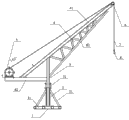
Fig. 1 is a foundation construction foundation ditch described in the utility model with small-sized loop wheel machine structural representation.
The specific embodiment
For technological means, creation characteristic that the utility model is realized, reach purpose and effect is easy to understand, below in conjunction with concrete diagram, further set forth the utility model.
Referring to Fig. 1, the small-sized loop wheel machine of a kind of foundation construction foundation ditch comprises a base 1, and base 1 is provided with balance weight 11, is used for balancing hoisting machine weight, and is unbalance when preventing the loop wheel machine hoisting.Can also be provided with movably traveling gear (not shown) in addition on the base.
Above fixed pedestal bar 2, connect a rotation strut bar 3 again, rotation strut bar 3 has been provided with the arm 4 of reusing, arm 4 bottoms have been provided with the motor 5 of reusing, arm 4 tops are provided with a pulley 6, motor 5 has been connected with reuses steel rope 7, steel rope 7 other ends are walked around the pulley 6 on arm top, and connection one is used for the suspension hook 8 of lifting cargo.Steel rope is Φ 8 steel ropes.Can bear 1 ton weight.
Be provided with rotating bearing 31 between fixed pedestal bar 2 and the rotation strut bar 3.Make parts such as rotation strut bar 3 and arm 4 to rotate.Arm 4 is 140 ° with the inclination angle of horizontal direction as shown in the figure.
As a mobile jib, solid drawn pipe 41 bottoms connect a horizontal solid drawn pipe 42 to arm 4 by a bevelled Φ 89 * 8 solid drawn pipes 41, and motor is arranged on solid drawn pipe 42 tail ends.Be provided with the solid drawn pipe 43 of a bevelled Φ 38 * 5 below solid drawn pipe 41, the front end that solid drawn pipe 43 props up solid drawn pipe 42 forms stable triangular structure.Rotation strut bar 3 upper ends are against solid drawn pipe 41 middle parts on the lower side on the position, make whole triangle center drop on the rotation strut bar 3.The steel pipe that is provided with a plurality of sub-trusses in addition between solid drawn pipe 41 and solid drawn pipe 43 forms a plurality of triangle rock-steady structuries.
The described small-sized loop wheel machine of present embodiment uses around being arranged on foundation ditch, makes things convenient for the inside and outside goods of foundation ditch to transport, and saves manpower, increases work efficiency.
More than show and described groundwork of the present utility model, principal character and advantage of the present utility model.The technical personnel of the industry should be understood; the utility model is not restricted to the described embodiments; that describes in the foregoing description and the specification sheets just illustrates principle of the present utility model; the utility model also has various changes and modifications under the prerequisite that does not break away from the utility model spirit and scope, and these changes and improvements all fall in claimed the utility model scope.The claimed scope of the utility model is defined by appending claims and equivalent thereof.
Claims (4)
1. the small-sized loop wheel machine of foundation construction foundation ditch, comprise a base, it is characterized in that base is provided with a fixed pedestal bar, the fixed pedestal bar connects a rotation strut bar, the rotation strut bar has been provided with the arm of reusing, the arm bottom has been provided with the motor of reusing, and the arm top is provided with a pulley, and motor has been connected with reuses steel rope, the steel rope other end is walked around the pulley on arm top, and connection one is used for the suspension hook of lifting cargo.
2. the small-sized loop wheel machine of foundation construction foundation ditch according to claim 1 is characterized in that, is provided with rotating bearing between fixed pedestal bar and the rotation strut bar.
3. the small-sized loop wheel machine of foundation construction foundation ditch according to claim 1 is characterized in that base is provided with balance weight.
4. the small-sized loop wheel machine of foundation construction foundation ditch according to claim 1 is characterized in that, also is provided with movably traveling gear on the base.
Priority Applications (1)
| Application Number | Priority Date | Filing Date | Title |
|---|---|---|---|
| CN 201120063197 CN201952131U (en) | 2011-03-11 | 2011-03-11 | Small crane for construction foundation pit |
Applications Claiming Priority (1)
| Application Number | Priority Date | Filing Date | Title |
|---|---|---|---|
| CN 201120063197 CN201952131U (en) | 2011-03-11 | 2011-03-11 | Small crane for construction foundation pit |
Publications (1)
| Publication Number | Publication Date |
|---|---|
| CN201952131U true CN201952131U (en) | 2011-08-31 |
Family
ID=44496253
Family Applications (1)
| Application Number | Title | Priority Date | Filing Date |
|---|---|---|---|
| CN 201120063197 Expired - Lifetime CN201952131U (en) | 2011-03-11 | 2011-03-11 | Small crane for construction foundation pit |
Country Status (1)
| Country | Link |
|---|---|
| CN (1) | CN201952131U (en) |
Cited By (4)
| Publication number | Priority date | Publication date | Assignee | Title |
|---|---|---|---|---|
| CN103010965A (en) * | 2012-11-23 | 2013-04-03 | 安徽省电力公司阜阳供电公司 | Special tool of 110kVGW4-type for hoisting switch blades and porcelain bottles |
| CN107986168A (en) * | 2017-11-24 | 2018-05-04 | 无锡南理工新能源电动车科技发展有限公司 | A kind of portable crane |
| CN107986167A (en) * | 2017-11-15 | 2018-05-04 | 南宁晟景工程咨询有限公司 | A kind of lifting device |
| CN108046119A (en) * | 2017-12-04 | 2018-05-18 | 浙江海洋大学 | Wharf crane |
-
2011
- 2011-03-11 CN CN 201120063197 patent/CN201952131U/en not_active Expired - Lifetime
Cited By (4)
| Publication number | Priority date | Publication date | Assignee | Title |
|---|---|---|---|---|
| CN103010965A (en) * | 2012-11-23 | 2013-04-03 | 安徽省电力公司阜阳供电公司 | Special tool of 110kVGW4-type for hoisting switch blades and porcelain bottles |
| CN107986167A (en) * | 2017-11-15 | 2018-05-04 | 南宁晟景工程咨询有限公司 | A kind of lifting device |
| CN107986168A (en) * | 2017-11-24 | 2018-05-04 | 无锡南理工新能源电动车科技发展有限公司 | A kind of portable crane |
| CN108046119A (en) * | 2017-12-04 | 2018-05-18 | 浙江海洋大学 | Wharf crane |
Similar Documents
| Publication | Publication Date | Title |
|---|---|---|
| CN201809036U (en) | Hanging hopper with detachable chassis | |
| CN201952131U (en) | Small crane for construction foundation pit | |
| CN207192616U (en) | A kind of gantry crane for preventing that goods from rocking | |
| CN104787690A (en) | Single-action arm ground lifting pole with flowing water counterweight system | |
| CN103832933B (en) | A kind of group tower tower crane with auxiliary | |
| CN108726397A (en) | A kind of underground mine use stent-type hydraulic crane device | |
| WO2022111218A1 (en) | Pile casing hoisting arm | |
| CN103058069B (en) | Horizontal arm tower-type crane | |
| CN204057766U (en) | Mast hanging device | |
| CN203998705U (en) | Single arm frame steel wire rope luffing stationary crane | |
| CN202379648U (en) | Portable mobile crane | |
| CN102351129B (en) | Super-lifting device for improving lifting performance of crane and crane | |
| CN106986267A (en) | A kind of four hook blocks fortune tipping bucket crane | |
| CN203411229U (en) | Lifting appliance with switchable states | |
| CN215048217U (en) | Operation platform and tower crane with external hanging suspender | |
| CN202829361U (en) | Small-size hoisting machine | |
| CN205527498U (en) | Utilize pulley system's hoist and mount and conveyer | |
| CN205527409U (en) | Portable hoist | |
| CN205527413U (en) | Hang cantilever crane | |
| CN85200231U (en) | A crane with its centre of gravity fixed on the vertical middle line | |
| CN204174938U (en) | A kind of concrete rotates carriage | |
| CN203740914U (en) | Multidirectional lifting frame | |
| CN105836633A (en) | Fixed type intelligent crane device | |
| CN205472332U (en) | Rotatable simple and easy armful of pole hoist | |
| CN202626840U (en) | Hanging basket device used in construction of slag retaining wall of railway cast-in-situ edge beam |
Legal Events
| Date | Code | Title | Description |
|---|---|---|---|
| C14 | Grant of patent or utility model | ||
| GR01 | Patent grant | ||
| CX01 | Expiry of patent term | ||
| CX01 | Expiry of patent term |
Granted publication date: 20110831 |