CN201920932U - Electric toothbrush - Google Patents
Electric toothbrush Download PDFInfo
- Publication number
- CN201920932U CN201920932U CN2010206773689U CN201020677368U CN201920932U CN 201920932 U CN201920932 U CN 201920932U CN 2010206773689 U CN2010206773689 U CN 2010206773689U CN 201020677368 U CN201020677368 U CN 201020677368U CN 201920932 U CN201920932 U CN 201920932U
- Authority
- CN
- China
- Prior art keywords
- toothbrush
- gear
- electric toothbrush
- driving device
- head toothbrushes
- Prior art date
- Legal status (The legal status is an assumption and is not a legal conclusion. Google has not performed a legal analysis and makes no representation as to the accuracy of the status listed.)
- Expired - Fee Related
Links
Images


Landscapes
- Brushes (AREA)
Abstract
The utility model discloses an electric toothbrush which comprises a toothbrush shell, an electric toothbrush actuating device, a toothbrush head and a battery cover, wherein the electric toothbrush actuating device, the toothbrush shell and the battery cover are arranged in the toothbrush shell; the electric toothbrush actuating device comprises an actuating device bracket, a motor, a gear transmission mechanism and a cam transmission mechanism; the gear transmission mechanism comprises a small bevel gear, a big bevel gear, a cylindrical gear A, a middle cylindrical gear and a main cylindrical gear, wherein the small bevel gear is connected to the spindle end of the motor; the big bevel gear is meshed with the small bevel gear; the cylindrical gear A and the big bevel gear coaxially and synchronously rotate; the middle cylindrical gear and the main cylindrical gear are sequentially meshed and driven with the cylindrical gear A; the cam transmission mechanism comprises eccentric wheels and two slide blocks, wherein the eccentric wheels are arranged on two sides of the middle cylindrical gear; the chutes of the two slide blocks are in sliding fit with the eccentric wheels; one sides of the slide blocks are in sliding guidance fit with the inner wall of the bracket of the actuating device; and each slide block comprises a connecting shaft which is connected to the upper end of a slide block body and extends out of the toothbrush shell to be connected with the toothbrush head. The electric toothbrush has the advantages of small energy loss, strong cleaning capability and high efficiency, is easy to realize and has small possibility of generating faults.
Description
Technical field
This utility model relates to a kind of toothbrush, relates in particular to a kind of electric toothbrush.
Background technology
In traditional electric toothbrush, the high speed rotating of motor is converted into the linear reciprocating motion or the crankmotion of head toothbrushes by gear or cam mechanism, and shakes by a small margin, to reach the purpose of cleaning teeth.
In traditional electric toothbrush, the reciprocating motion of head toothbrushes is generally single shaft and drives single head toothbrushes and carry out cleaning of teeth work, perhaps carries out cleaning of teeth work for the head toothbrushes of single crankmotion.Wherein, the electric toothbrush drive part of traditional reciprocal rotating electric toothbrush as depicted in figs. 1 and 2.When using these traditional electric toothbrushes, owing to have only a head toothbrushes crankmotion or vibrations by a small margin, so the user needs first one side to tooth to clean in use again another side is cleaned, from outside to inside or from inside to outside promptly, or repeatedly tooth is carried out inside and outside repeatedly cleaning.Make that like this time of brushing teeth is long, it is clean that some tooth dead angle is not easy cleaning; And motor energy often energy loss is bigger after being converted into by a small margin vibrations and crankmotion, the efficient reduction.How to allow the toothbrush can be quick, cleaning teeth becomes the present difficult problem that solves of needing efficiently.
The utility model content
The technical problems to be solved in the utility model be the defective at conventional power toothbrush provide a kind of fast, efficient, electric toothbrush that cleaning capacity is strong.
The technical scheme that its technical problem that solves this utility model adopts is:
A kind of electric toothbrush, comprise the toothbrush shell, be located at driving device for electric toothbrush, head toothbrushes and battery cover in the toothbrush shell, this battery cover is connected this toothbrush shell lower end, and described driving device for electric toothbrush comprises the driving device support and is installed on driving device support interior motor, gear drive and cam drive;
Described gear drive comprise the cone pinion that is connected in the motor spindle end, rotational support on the driving device support and with the large bevel gear of cone pinion engagement, with the roller gear A of the coaxial synchronous rotation of this large bevel gear and with intermediate cylindrical gear and the main roller gear of roller gear A engaged transmission successively; Described intermediate cylindrical gear one end rotational support on the driving device support, other end rotational support is on a cross structure, the two ends of this cross structure are fixed on the inwall of driving device support, and described main roller gear two ends rotational support is on described driving device support;
Described cam drive comprises two slide blocks that the eccentric of being located at main roller gear two sides, chute are slidingly matched with described eccentric respectively, one side of described slide block cooperates with the inwall slide-and-guide of described driving device support, and described slide block comprises the connecting axle that is connected the slide body upper end, stretches out the toothbrush shell and be connected with a head toothbrushes.
Wherein, described two eccentric phase places being located at main roller gear two sides are identical.
Wherein, described two eccentric phase contrasts being located at main roller gear two sides are 180 degree.
Wherein, described head toothbrushes is made up of symmetric two sub-head toothbrushes, and the bristles on two sub-head toothbrushes is relative, and the slit is left in the centre.
Wherein, the intermediary slit of bristles on described two sub-head toothbrushes is 0.1mm-0.9mm.
Wherein, described toothbrush shell is made up of upper casing and lower casing, and this toothbrush shell and described battery cover form an enclosed space.
Wherein, described cone pinion interference is pressed on the turning cylinder of motor.
The beneficial effects of the utility model are:
1) in this utility model, do linear reciprocating motion because motor drives head toothbrushes by simple gear drive and cam drive, so energy loss is less, the head toothbrushes cleaning capacity is strong, the efficient height;
2) this utility model has adopted the two head toothbrushes with unique texture, can be to last lower teeth, and the outside covers simultaneously in the tooth, thereby can shorten brushing time greatly, and conventional power toothbrush has improved efficient significantly relatively;
3) structure of driving device for electric toothbrush of the present utility model and head toothbrushes is all comparatively simple, is easy to realize, and is not easy to break down.
Description of drawings
The utility model is described in further detail below in conjunction with drawings and Examples, in the accompanying drawing:
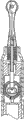
Fig. 1 and Fig. 2 are the structural representation of the electric toothbrush drive part of traditional progressive rotation type electric toothbrush, and wherein Fig. 1 is a front view, and Fig. 2 is a side view.
The overall structure sketch map of the driving device for electric toothbrush that Fig. 3 and Fig. 4 provide for this utility model embodiment, wherein Fig. 3 is a front view, Fig. 4 is a side view.
The STRUCTURE DECOMPOSITION sketch map of the driving device for electric toothbrush that Fig. 5 provides for this utility model embodiment.
The profile sketch map of the head toothbrushes of the electric toothbrush that Fig. 6 provides for this utility model embodiment.
Fig. 7 and Fig. 8 plant a mao sketch map for the head toothbrushes first step that this utility model embodiment provides.
Fig. 9 and Figure 10 plant a mao sketch map for second step of head toothbrushes that this utility model embodiment provides.
Figure 11 and Figure 12 plant a mao sketch map for the 3rd step of head toothbrushes that this utility model embodiment provides.
Figure 13 and Figure 14 plant a mao sketch map for the 4th step of head toothbrushes that this utility model embodiment provides.
The position view of two sub-head toothbrushes of the head toothbrushes that Figure 15 provides for this utility model embodiment.
The using method sketch map of the electric toothbrush that Figure 16 provides for this utility model embodiment.
[figure number explanation]
1 battery cover, 2 toothbrush shells, 3 driving device supports, 4 motors
5 cone pinions, 6 large bevel gears, 6 ' roller gear A, 7 connecting axles
8 intermediate cylindrical gears, 9 cross structures, 10 main roller gear 11 slide blocks
12 connecting axles, 13 head toothbrushes
The specific embodiment
See also Fig. 3, Fig. 4 and Fig. 5, among this utility model embodiment, electric toothbrush comprises battery cover 1, toothbrush shell 2, driving device for electric toothbrush, two head toothbrushes 13.Wherein, 2 water-tights of toothbrush shell and supporting role; Driving device for electric toothbrush is located in the toothbrush shell 2, and stretches out by two connecting axles 12 that toothbrush shell 2 is outer to be connected with two head toothbrushes 13 respectively simultaneously, drives two head toothbrushes 13 and carries out linear reciprocating motion.
Driving device for electric toothbrush includes a driving device support 3, motor 4, gear driven mechanism and cam drive mechanism, driving device support 3 wherein plays fixed support and modular power toothbrush drive part, and motor 4, gear driven mechanism and cam drive mechanism are installed in the driving device support 3; Wherein, gear driven mechanism comprises cone pinion 5, large bevel gear 6, roller gear A 6 ', intermediate cylindrical gear 8 and main roller gear 10, cam drive mechanism comprises the eccentric of being located at main roller gear 10 two sides, the slide block 11 that cooperates with eccentric and the connecting axle 12 of injection moulding on slide block 11, is specially:
At the fixing cone pinion 5 of motor 4 spindle ends, this cone pinion 5 is pressed into the spindle end of motor 4 for interference; Large bevel gear 6 rotational support mesh on driving device support 3 and with cone pinion 5; Roller gear A 6 ' and large bevel gear 6 coaxial synchronous rotations, and intermediate cylindrical gear 8 and main roller gear 10 mesh with roller gear A 6 ' successively; Intermediate cylindrical gear 8 one end rotational support on the driving device support 3, an end rotational support on a cross structure 9, the two ends of this cross structure 9 are fixed on the inwall of driving device support 3;
The two sides of main roller gear 10 respectively are provided with an eccentric, and two slide blocks 11 are slidingly matched by chute and eccentric respectively; Be injected with one respectively on two slide blocks 11 and be with the connecting axle 12 of screens, these two connecting axles 12 engage with a head toothbrushes 13 respectively, thereby realize the work that moves up and down of head toothbrushes when the turning cylinder motion of motor 4.In addition, the eccentric phase place of main roller gear 10 two sides can be identical, also can differ 180 degree; The material of connecting axle 7 and connecting axle 12 is preferably rustless steel, and the material of driving device support 3 is preferably plastics.
Above-mentioned electric toothbrush is when work, the turning cylinder high speed rotating of motor 4, by cone pinion 5 rotation is delivered to large bevel gear 6, large bevel gear 6 has played the dual function that reduces rotating speed and change rotation direction, by roller gear A 6 ', intermediate cylindrical gear 8 rotation is delivered to main roller gear 10 then, main roller gear 10 further reduces rotating speed so that the motion of toothbrush is converted to the acceptable operating rate; Because respectively there is an eccentric two sides of main roller gear 10, these two eccentrics are one with main roller gear 10 and respectively cooperate with a slide block 11, so when main roller gear 10 rotates, if two eccentric phase places are identical, then two eccentrics can drive corresponding slide block 11 and realize synchronous seesawing under the guide effect of driving device support 3, finally drive two synchronous linear reciprocating motions of head toothbrushes 13 property performance period; If two eccentric phase contrasts are 180 degree, then two eccentrics can drive corresponding slide block 11 and realize tandem asynchronous seesawing under the guide effect of driving device support 3, finally drive two opposite linear reciprocating motions of head toothbrushes 13 property performance period.
In the present embodiment, the structure of the head toothbrushes 13 that is adopted as shown in Figure 6, this head toothbrushes contour structures uniqueness, complex process meets human engineering, has symmetric two sub-head toothbrushes, and the bristles on two sub-head toothbrushes is relative, the slit is left in the centre.In addition, for ease of using, be implanted with the bristles of different length on each sub-head toothbrushes, the method for implantation of bristles is: the first step, as shown in Figure 7 and Figure 8, implant brachydont bristle; In second step,, implant equidirectional than the long teeth bristle as Fig. 9 and shown in Figure 10; In the 3rd step,, implant the long teeth bristle of other direction as Figure 11 and shown in Figure 12; In the 4th step,, implant long teeth bristle as Figure 13 and shown in Figure 14.This head toothbrushes operation is more, but makes bristles reach multiple length dimension, multiple angles, and final the realization can be cleaned comprehensively and effectively to tooth.In addition, preferably, as shown in figure 15, the slit about two sub-head toothbrushes intermediate formation 0.1-0.9mm of head toothbrushes is so that the tooth incision.
Figure 16 is the using method sketch map of electric toothbrush in the present embodiment, because this electric toothbrush has 2 head toothbrushes that can carry out reverse linear reciprocating motion, and each head toothbrushes has symmetric two sub-head toothbrushes, thereby when brushing teeth, can clean the inboard and the outside of top and following tooth simultaneously, not only cleaning capacity is strong, and has shortened the time of brushing teeth greatly, improve efficient, improved the utilization rate of motor energy.
Above embodiment is only unrestricted in order to the explanation the technical solution of the utility model, only with reference to preferred embodiment this utility model is had been described in detail.Those of ordinary skill in the art should be appreciated that and can make amendment or be equal to replacement the technical solution of the utility model, and do not break away from the spirit and scope of technical solutions of the utility model, all should be encompassed in the middle of the claim scope of the present utility model.
Claims (7)
1. electric toothbrush, comprise the toothbrush shell, be located at driving device for electric toothbrush, head toothbrushes and battery cover in the toothbrush shell, this battery cover is connected this toothbrush shell lower end, it is characterized in that described driving device for electric toothbrush comprises the driving device support and is installed on driving device support interior motor, gear drive and cam drive;
Described gear drive comprise the cone pinion that is connected in the motor spindle end, rotational support on the driving device support and with the large bevel gear of cone pinion engagement, with the roller gear A of the coaxial synchronous rotation of this large bevel gear and with intermediate cylindrical gear and the main roller gear of roller gear A engaged transmission successively; Described intermediate cylindrical gear one end rotational support on the driving device support, other end rotational support is on a cross structure, the two ends of this cross structure are fixed on the inwall of driving device support, and described main roller gear two ends rotational support is on described driving device support;
Described cam drive comprises two slide blocks that the eccentric of being located at main roller gear two sides, chute are slidingly matched with described eccentric respectively, one side of described slide block cooperates with the inwall slide-and-guide of described driving device support, and described slide block comprises the connecting axle that is connected the slide body upper end, stretches out the toothbrush shell and be connected with a head toothbrushes.
2. electric toothbrush as claimed in claim 1 is characterized in that, described two eccentric phase places being located at main roller gear two sides are identical.
3. electric toothbrush as claimed in claim 1 is characterized in that, described two eccentric phase contrasts being located at main roller gear two sides are 180 degree.
4. as the arbitrary described electric toothbrush of claim 1 to 3, it is characterized in that described head toothbrushes is made up of symmetric two sub-head toothbrushes, and the bristles on two sub-head toothbrushes is relative, the slit is left in the centre.
5. electric toothbrush as claimed in claim 4 is characterized in that, the intermediary slit of bristles on described two sub-head toothbrushes is 0.1mm-0.9mm.
6. electric toothbrush as claimed in claim 1 is characterized in that, described toothbrush shell is made up of upper casing and lower casing, and this toothbrush shell and described battery cover form an enclosed space.
7. electric toothbrush as claimed in claim 1 is characterized in that, described cone pinion interference is pressed on the turning cylinder of motor.
Priority Applications (1)
| Application Number | Priority Date | Filing Date | Title |
|---|---|---|---|
| CN2010206773689U CN201920932U (en) | 2010-12-22 | 2010-12-22 | Electric toothbrush |
Applications Claiming Priority (1)
| Application Number | Priority Date | Filing Date | Title |
|---|---|---|---|
| CN2010206773689U CN201920932U (en) | 2010-12-22 | 2010-12-22 | Electric toothbrush |
Publications (1)
| Publication Number | Publication Date |
|---|---|
| CN201920932U true CN201920932U (en) | 2011-08-10 |
Family
ID=44424808
Family Applications (1)
| Application Number | Title | Priority Date | Filing Date |
|---|---|---|---|
| CN2010206773689U Expired - Fee Related CN201920932U (en) | 2010-12-22 | 2010-12-22 | Electric toothbrush |
Country Status (1)
| Country | Link |
|---|---|
| CN (1) | CN201920932U (en) |
Cited By (1)
| Publication number | Priority date | Publication date | Assignee | Title |
|---|---|---|---|---|
| CN112451146A (en) * | 2019-09-08 | 2021-03-09 | 郑云兵 | Electric toothbrush |
-
2010
- 2010-12-22 CN CN2010206773689U patent/CN201920932U/en not_active Expired - Fee Related
Cited By (1)
| Publication number | Priority date | Publication date | Assignee | Title |
|---|---|---|---|---|
| CN112451146A (en) * | 2019-09-08 | 2021-03-09 | 郑云兵 | Electric toothbrush |
Similar Documents
| Publication | Publication Date | Title |
|---|---|---|
| CN206701804U (en) | A kind of plant equipment for being used to clean various agricultural product | |
| CN101112333B (en) | Electric tooth brushing device | |
| CN209613615U (en) | Automatic cleaning device | |
| CN102920520B (en) | Omnibearing electric toothbrush | |
| CN201920932U (en) | Electric toothbrush | |
| CN102086580A (en) | Washing mode of washing machine, washing machine thereof and speed reduction clutch thereof | |
| CN206935849U (en) | A kind of solar energy power generating board cleaning machine | |
| CN2683063Y (en) | Tridimensional electric and manual dual purpose toothbrush | |
| CN109174546A (en) | Technological process of making antique timber | |
| CN111438153B (en) | High-efficient belt cleaning device of clinical laboratory's test tube | |
| CN108478238A (en) | A kind of medical oral section sampler | |
| CN205215161U (en) | Cup utensil cleaner | |
| CN108286233B (en) | A kind of follow-on environmental treatment rubbish removing equipment | |
| CN2820127Y (en) | Improved electric tooth-brush | |
| CN201064496Y (en) | Electric toothbrush head | |
| CN108018809B (en) | A kind of novel environmental treatment rubbish removing equipment | |
| CN205729550U (en) | A kind of dual-cavity facing band erects the electric toothbrush of brush | |
| CN206324872U (en) | A kind of low-angle left-right rotation device and the electric toothbrush using the tumbler | |
| CN207508533U (en) | A kind of optical-fiber laser cutting machine synchronizes mutual zapping | |
| CN206001770U (en) | A kind of refrigerator-freezer being easy to movement | |
| CN220862258U (en) | Gear pump cleaning mechanism | |
| CN218079268U (en) | Transparent eye cream cleaning tank | |
| CN208837030U (en) | A kind of food processing yellow peach fine hair processing unit | |
| CN214683387U (en) | Belt cleaning device is used in eye cream production | |
| CN219595230U (en) | Blister medicine filling device |
Legal Events
| Date | Code | Title | Description |
|---|---|---|---|
| C14 | Grant of patent or utility model | ||
| GR01 | Patent grant | ||
| CF01 | Termination of patent right due to non-payment of annual fee | ||
| CF01 | Termination of patent right due to non-payment of annual fee |
Granted publication date: 20110810 Termination date: 20171222 |