CN201917841U - Voltage-controlled constant-current source circuit - Google Patents
Voltage-controlled constant-current source circuit Download PDFInfo
- Publication number
- CN201917841U CN201917841U CN 201020689020 CN201020689020U CN201917841U CN 201917841 U CN201917841 U CN 201917841U CN 201020689020 CN201020689020 CN 201020689020 CN 201020689020 U CN201020689020 U CN 201020689020U CN 201917841 U CN201917841 U CN 201917841U
- Authority
- CN
- China
- Prior art keywords
- circuit
- dds
- chip
- voltage
- current source
- Prior art date
- Legal status (The legal status is an assumption and is not a legal conclusion. Google has not performed a legal analysis and makes no representation as to the accuracy of the status listed.)
- Expired - Lifetime
Links
- 230000003750 conditioning effect Effects 0.000 claims abstract description 15
- 230000005684 electric field Effects 0.000 abstract description 2
- 238000006243 chemical reaction Methods 0.000 abstract 2
- 230000015572 biosynthetic process Effects 0.000 abstract 1
- 238000003786 synthesis reaction Methods 0.000 abstract 1
- 238000010586 diagram Methods 0.000 description 2
- 230000009286 beneficial effect Effects 0.000 description 1
- 210000001174 endocardium Anatomy 0.000 description 1
- 238000013507 mapping Methods 0.000 description 1
- 238000012986 modification Methods 0.000 description 1
- 230000004048 modification Effects 0.000 description 1
Images
Landscapes
- Control Of Electrical Variables (AREA)
Abstract
The utility model discloses a voltage-controlled constant-current source circuit, which comprises a single-chip microcomputer, a power supply circuit, direct digital synthesis (DDS) chips, a signal conditioning circuit and a voltage-to-current (V/I) conversion circuit, wherein the single-chip microcomputer is connected with the DDS chips, the DDS chips are connected with the signal conditioning circuit, the power supply circuit is respectively connected with the single-chip microcomputer, the power supply circuit, DDS chips, the signal conditioning circuit and the V/I conversion circuit, and the single-chip microcomputer controls three DDS chips. The voltage-controlled constant-current source circuit has the advantages that sinusoidal voltage signals generated by a signal generator can be converted into constant-current signals, the circuit is easy to connect, the performance is stable, the simultaneous loading of multi-channel electric fields can be realized and the constant-current characteristic of the circuit under the condition of high impedance can be realized.
Description
Technical field
The utility model relates to a kind of constant-current source circuit, relates in particular to a kind of voltage controlled current source circuit.
Background technology
Only considered human body impedance when the Endocardium three-dimension mapping, promptly only accounted for the very little part of pull-up resistor, and in fact the contact impedance of electrode and skin is bigger, when load was excessive, common discharge circuit was difficult to meet the demands.Therefore, must improve existing circuit makes it still have constant-current characteristics under the heavy load situation.
The utility model content
The purpose of this utility model provides a kind of voltage controlled current source circuit, the sine voltage signal of signal generator can be converted into constant current signal.
To achieve these goals, the utility model is by the following technical solutions:
A kind of voltage controlled current source circuit, wherein, the voltage controlled current source circuit comprises single-chip microcomputer, power circuit, DDS chip, signal conditioning circuit and V/I change-over circuit, described single-chip microcomputer connects the DDS chip, the DDS chip connects signal conditioning circuit, power circuit connects single-chip microcomputer, DDS chip, signal conditioning circuit and V/I change-over circuit respectively, three DDS chips of described Single-chip Controlling.
Further, described DDS chip adopts the AD9851 chip.
The beneficial effects of the utility model are:
The utility model circuit ease of connection, stable performance can realize that the multichannel electric field loads simultaneously; Can satisfy the constant-current characteristics of circuit under big impedance conditions, load on 30KHz, below 0~5K Ω, can load simultaneously, under 5KHz, 20~60K Ω condition, circuit also can keep constant-current characteristics preferably.
Other advantages of the present utility model, target and feature will be set forth to a certain extent in the following description, and to a certain extent, based on being conspicuous to those skilled in the art, perhaps can from practice of the present utility model, obtain instruction to investigating hereinafter.Target of the present utility model and other advantages can realize and obtain by specifically noted structure in following instructions or the accompanying drawing.
Description of drawings
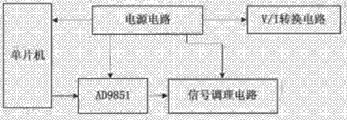
Fig. 1 is a structured flowchart of the present utility model;
Fig. 2 is the utility model V/I change-over circuit schematic diagram.
Embodiment
Below in conjunction with drawings and Examples the utility model is further described:
As shown in Figure 1, the utility model comprises single-chip microcomputer, power circuit, DDS chip, signal conditioning circuit and V/I change-over circuit, single-chip microcomputer connects the DDS chip, the DDS chip connects signal conditioning circuit, power circuit connects single-chip microcomputer, DDS chip, signal conditioning circuit and V/I change-over circuit respectively, and the DDS chip adopts the AD9851 chip.
Synthetic (DDS) technology of the Direct Digital that adopts, by three DDS chips of Single-chip Controlling, produce three road different frequency sine voltage signals, voltage signal is after the signal conditioning circuit conditioning, adopt voltage controlled current source technology (VCCS), voltage signal is converted to the constant sinusoidal current signal of three road different frequencies.DDS technical implementation way main and FPGA programming mode and special-purpose DDS chip, the utility model adopts special-purpose DDS chip AD9851 to realize that performance index are good, have high cost performance.
Figure 2 shows that V/I change-over circuit schematic diagram.Because the design feature of DDS chip self inevitably contains high frequency noise in the signal of AD9851 chip output, the amplitude range of exporting sinusoidal signal simultaneously is also less, therefore must carry out the signal adjustment, to satisfy the request for utilization of subsequent conditioning circuit.
Explanation is at last, above embodiment is only unrestricted in order to the explanation the technical solution of the utility model, other modifications that those of ordinary skills make the technical solution of the utility model or be equal to replacement, only otherwise break away from the spirit and scope of technical solutions of the utility model, all should be encompassed in the middle of the claim scope of the present utility model.
Claims (2)
1. voltage controlled current source circuit, it is characterized in that: the voltage controlled current source circuit comprises single-chip microcomputer, power circuit, DDS chip, signal conditioning circuit and V/I change-over circuit, described single-chip microcomputer connects the DDS chip, the DDS chip connects signal conditioning circuit, power circuit connects single-chip microcomputer, DDS chip, signal conditioning circuit and V/I change-over circuit respectively, three DDS chips of described Single-chip Controlling.
2. a kind of voltage controlled current source circuit according to claim 1 is characterized in that: described DDS chip adopts the AD9851 chip.
Priority Applications (1)
| Application Number | Priority Date | Filing Date | Title |
|---|---|---|---|
| CN 201020689020 CN201917841U (en) | 2010-12-30 | 2010-12-30 | Voltage-controlled constant-current source circuit |
Applications Claiming Priority (1)
| Application Number | Priority Date | Filing Date | Title |
|---|---|---|---|
| CN 201020689020 CN201917841U (en) | 2010-12-30 | 2010-12-30 | Voltage-controlled constant-current source circuit |
Publications (1)
| Publication Number | Publication Date |
|---|---|
| CN201917841U true CN201917841U (en) | 2011-08-03 |
Family
ID=44417635
Family Applications (1)
| Application Number | Title | Priority Date | Filing Date |
|---|---|---|---|
| CN 201020689020 Expired - Lifetime CN201917841U (en) | 2010-12-30 | 2010-12-30 | Voltage-controlled constant-current source circuit |
Country Status (1)
| Country | Link |
|---|---|
| CN (1) | CN201917841U (en) |
Cited By (1)
| Publication number | Priority date | Publication date | Assignee | Title |
|---|---|---|---|---|
| CN107332515A (en) * | 2017-07-13 | 2017-11-07 | 卡斯柯信号有限公司 | A kind of C6 signal generation devices of the LEU based on DDS |
-
2010
- 2010-12-30 CN CN 201020689020 patent/CN201917841U/en not_active Expired - Lifetime
Cited By (2)
| Publication number | Priority date | Publication date | Assignee | Title |
|---|---|---|---|---|
| CN107332515A (en) * | 2017-07-13 | 2017-11-07 | 卡斯柯信号有限公司 | A kind of C6 signal generation devices of the LEU based on DDS |
| CN107332515B (en) * | 2017-07-13 | 2024-04-05 | 卡斯柯信号有限公司 | A C6 signal generating device for LEU based on DDS |
Similar Documents
| Publication | Publication Date | Title |
|---|---|---|
| CN203154605U (en) | Portable constant-pulse-current parturition analgesia instrument | |
| CN106712258A (en) | Power supply system for photovoltaic and power grid interactive direct current air conditioner | |
| CN109120153A (en) | A kind of BUCK circuit and Switching Power Supply | |
| CN206650895U (en) | A kind of tunable optical color-adjustable RGB LEDs of direct current supply | |
| CN201917841U (en) | Voltage-controlled constant-current source circuit | |
| CN201926949U (en) | Voltage control constant-current source signal conditioning circuit | |
| CN209217796U (en) | A kind of power supply architecture | |
| CN201689651U (en) | Circuit capable of realizing the fixed frequency and adjusting the duty ratio by button | |
| CN201207614Y (en) | Full load flexible switch power supply control circuit | |
| CN203492198U (en) | Condenser microphone connecting line for providing phantom power via USB interface | |
| CN206686402U (en) | Wide input voltage phase-cut dimming circuit | |
| CN206413095U (en) | It is a kind of to receive the circuit that both-end radiofrequency signal is inputted with single ended input | |
| CN205847094U (en) | Numerical control regulated power supply | |
| CN204615643U (en) | The power circuit of communication base station remote power-feeding | |
| CN204836546U (en) | Integrated form audio signal player | |
| CN208954612U (en) | A kind of device for realizing the LCD display port with boosting and GPIO multiplexing | |
| CN202997620U (en) | High efficiency low consumption field emergency solar energy power supply management system | |
| CN206726079U (en) | A kind of intelligent current source | |
| CN203086140U (en) | Intelligent electricity-saving controller | |
| CN207638936U (en) | A kind of OLED intelligent desk lamps having wireless charging function | |
| CN205515998U (en) | Meridian and collateral therapeutic apparatus | |
| CN209462665U (en) | A kind of controllable silicon light modulation is actively released control circuit | |
| CN201418191Y (en) | Bulb brightness regulator | |
| CN220822639U (en) | Low-cost battery power supply device | |
| CN207719837U (en) | A kind of wireless transmission battery |
Legal Events
| Date | Code | Title | Description |
|---|---|---|---|
| C14 | Grant of patent or utility model | ||
| GR01 | Patent grant | ||
| CX01 | Expiry of patent term |
Granted publication date: 20110803 |
|
| CX01 | Expiry of patent term |