CN201908959U - High-speed rotator supporting mechanism - Google Patents
High-speed rotator supporting mechanism Download PDFInfo
- Publication number
- CN201908959U CN201908959U CN2010206316999U CN201020631699U CN201908959U CN 201908959 U CN201908959 U CN 201908959U CN 2010206316999 U CN2010206316999 U CN 2010206316999U CN 201020631699 U CN201020631699 U CN 201020631699U CN 201908959 U CN201908959 U CN 201908959U
- Authority
- CN
- China
- Prior art keywords
- transmission shaft
- constraint
- diameter
- supporting mechanism
- wheels
- Prior art date
- Legal status (The legal status is an assumption and is not a legal conclusion. Google has not performed a legal analysis and makes no representation as to the accuracy of the status listed.)
- Expired - Fee Related
Links
Images


Landscapes
- Rolls And Other Rotary Bodies (AREA)
Abstract
The utility model relates to a high-speed rotator supporting mechanism, which comprises a transmission shaft, and is characterized in that three evenly distributed constraint wheels contacting with the transmission shaft are arranged on the circumference of a supporting position of the transmission shaft, the three constraint wheels are mounted on respective bearings respectively, and the diameter of each constraint wheel is 1.5-10 times of the shaft diameter of the supporting position of the transmission shaft. The rotational speed of the transmission shaft can be transferred to the supported bearings through the constraint wheels, and the diameter of each constraint wheel is larger than the shaft diameter of the supporting position of the transmission shaft by a multiple larger than one, namely the rotational speed of the constraint wheels is in lowered multiple relationship relative to that of the transmission shaft, so that the rotational speed of the constraint wheels is within the limit rotational speed range allowed by the bearings. Therefore, the high-speed rotator supporting mechanism has the advantages of reasonable structure, long service life and the like, and is especially applicable to filament throwing roll shafts for supporting a refractory fiber filament throwing machine.
Description
Technical field
The utility model belongs to driving mechanism, is a kind of high speed rotary body supporting mechanism.
Background technique
In driving mechanism, adopt the supporting part of bearing usually as solid of rotation, but for high-revolving transmission shaft, for example: transmission shaft rotating speed>10000 rev/min, when the transmission shaft of high speed rotary directly is installed on the bearing, the normal limit speed that exceeds the bearing permission because of the rotating speed of transmission shaft is too high, will reduce the working life of bearing, even cause the generation of accident because of damage of bearings.
Summary of the invention
The purpose of this utility model is to provide a kind of rational in infrastructure, the high speed rotary body supporting mechanism of long service life.
The purpose of this utility model is realized by following technological scheme: a kind of high speed rotary body supporting mechanism, it comprises transmission shaft, it is characterized in that: setting contacts with it and three uniform constraint wheels on the circumference of transmission shaft Support Position, and three constraints are taken turns on the bearing that is loaded on respectively separately.
The diameter of described constraint wheel is 1.5~10 times of the transmission shaft Support Position diameter of axle.
High speed rotary body supporting mechanism of the present utility model, contact with it owing to adopt on the circumference of transmission shaft Support Position, to be provided with, and three uniform constraint wheels, three constraints are taken turns on the bearing that is loaded on respectively separately, the rotating speed of transmission shaft passes to the bearing of support by the constraint wheel, because the diameter of constraint wheel is greater than the diameter of axle of transmission shaft Support Position, the diameter of constraint wheel and the transmission shaft Support Position diameter of axle are the multiple relation greater than 1, that is the rotating speed of the relative transmission shaft of rotating speed of constraint wheel is the multiple relation that reduces, the rotating speed that causes the constraint wheel is in the limit speed scope that bearing allows, therefore, have rational in infrastructure, advantages such as long service life are specially adapted to support the wire swaying roller axle of refractory fiber tumbling machine.
Description of drawings
Fig. 1 is a high speed rotary body supporting mechanism structural representation of the present utility model.
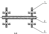
Fig. 2 is A-A cross-sectional schematic among Fig. 1 (two supporting form).
Fig. 3 is B-B cross-sectional schematic among Fig. 1 (single supporting form).
Embodiment
The utility model is described in further detail to utilize drawings and Examples below.
With reference to Fig. 1-3, high speed rotary body supporting mechanism of the present utility model has transmission shaft 2, contacts with it and uniform 3, three constraints of three constraint wheels are taken turns on 3 bearings 1 that are loaded on respectively separately being provided with on the circumference of transmission shaft 2 Support Positions.The diameter of described constraint wheel 3 is 1.5~10 times of the transmission shaft 2 Support Position diameters of axle.The transmission shaft 2 of this embodiment adopts two supporting forms.Also can single supporting form be set for the short pass moving axis in the intermediate support position of short pass moving axis.
High speed rotary body supporting mechanism of the present utility model does not limit to this embodiment, and those skilled in the art all belong to protection domain of the present utility model without any simple transformation of creative work.
Claims (2)
1. high speed rotary body supporting mechanism, it comprises transmission shaft, it is characterized in that: be provided with on the circumference of transmission shaft Support Position with it and contact and three uniform constraint wheels, three constraints are taken turns on the bearing that is loaded on respectively separately.
2. high speed rotary body supporting mechanism according to claim 1 is characterized in that: the diameter of described constraint wheel is 1.5~10 times of the transmission shaft Support Position diameter of axle.
Priority Applications (1)
| Application Number | Priority Date | Filing Date | Title |
|---|---|---|---|
| CN2010206316999U CN201908959U (en) | 2010-11-24 | 2010-11-24 | High-speed rotator supporting mechanism |
Applications Claiming Priority (1)
| Application Number | Priority Date | Filing Date | Title |
|---|---|---|---|
| CN2010206316999U CN201908959U (en) | 2010-11-24 | 2010-11-24 | High-speed rotator supporting mechanism |
Publications (1)
| Publication Number | Publication Date |
|---|---|
| CN201908959U true CN201908959U (en) | 2011-07-27 |
Family
ID=44301162
Family Applications (1)
| Application Number | Title | Priority Date | Filing Date |
|---|---|---|---|
| CN2010206316999U Expired - Fee Related CN201908959U (en) | 2010-11-24 | 2010-11-24 | High-speed rotator supporting mechanism |
Country Status (1)
| Country | Link |
|---|---|
| CN (1) | CN201908959U (en) |
Cited By (2)
| Publication number | Priority date | Publication date | Assignee | Title |
|---|---|---|---|---|
| CN103511471A (en) * | 2013-09-22 | 2014-01-15 | 西安交通大学 | Main shaft bearing and transmission device |
| CN112128252A (en) * | 2020-08-19 | 2020-12-25 | 北京北一机床股份有限公司 | Supporting mechanism and method for large-diameter continuous rotary long shaft |
-
2010
- 2010-11-24 CN CN2010206316999U patent/CN201908959U/en not_active Expired - Fee Related
Cited By (2)
| Publication number | Priority date | Publication date | Assignee | Title |
|---|---|---|---|---|
| CN103511471A (en) * | 2013-09-22 | 2014-01-15 | 西安交通大学 | Main shaft bearing and transmission device |
| CN112128252A (en) * | 2020-08-19 | 2020-12-25 | 北京北一机床股份有限公司 | Supporting mechanism and method for large-diameter continuous rotary long shaft |
Similar Documents
| Publication | Publication Date | Title |
|---|---|---|
| CN201908959U (en) | High-speed rotator supporting mechanism | |
| CN202379567U (en) | Jigger structure of outer rotor permanent magnet synchronous gearless traction machine | |
| CN201824239U (en) | Deep hole grinding motorized spindle | |
| CN204749748U (en) | Axle and wheel reduction's semi -axis stop device | |
| CN204237305U (en) | A kind of coiled strip unreeling structure | |
| CN204416987U (en) | A kind of hoisting crane rotatable pulley | |
| CN209367087U (en) | A kind of across steel billet chain transfer of mistake | |
| CN201799930U (en) | Grinding spindle lengthening mechanism | |
| CN103527717A (en) | Composite planet row structure adapting to high-rotation-speed working condition | |
| CN201296879Y (en) | Rope pulley of guide roll for paper making machine | |
| CN203023291U (en) | Bearing bush type magnetic suspension support mechanism and ball-milling device | |
| CN203223471U (en) | Bearing type magnetic suspension supporting mechanism and ball milling equipment | |
| CN103054512A (en) | Rotary plate of window cleaning machine | |
| CN201334562Y (en) | Draw shaft mounting structure | |
| CN202705952U (en) | Barrier brake bar installation structure and barrier | |
| CN205999306U (en) | A kind of experienced bulging carrier roller mechanism | |
| CN202916089U (en) | Auxiliary supporting device for a spindle of a rotary strength testing machine | |
| CN201471250U (en) | Roller grinding and polishing wheel supporting mechanism of full-automatic diamond grinding and polishing machine | |
| CN201405560Y (en) | Non-concentric transmission mechanism for wallpaper rotary screen printing machine | |
| CN202594633U (en) | Running wheel set for arc rail | |
| CN202981854U (en) | Window-cleaning machine turntable | |
| CN214732012U (en) | Steel pipe rotating transfer device | |
| CN203548568U (en) | Chained bearing block | |
| CN203412997U (en) | Brake device with ceramic friction sheet | |
| CN107785812A (en) | A kind of power transmission line installation apparatus when being used for construction of cable run |
Legal Events
| Date | Code | Title | Description |
|---|---|---|---|
| C14 | Grant of patent or utility model | ||
| GR01 | Patent grant | ||
| CF01 | Termination of patent right due to non-payment of annual fee |
Granted publication date: 20110727 Termination date: 20141124 |
|
| EXPY | Termination of patent right or utility model |