CN201902594U - Hydraulic and automatic ball valve - Google Patents
Hydraulic and automatic ball valve Download PDFInfo
- Publication number
- CN201902594U CN201902594U CN2010206326469U CN201020632646U CN201902594U CN 201902594 U CN201902594 U CN 201902594U CN 2010206326469 U CN2010206326469 U CN 2010206326469U CN 201020632646 U CN201020632646 U CN 201020632646U CN 201902594 U CN201902594 U CN 201902594U
- Authority
- CN
- China
- Prior art keywords
- piston
- valve
- joint
- cavity
- valve rod
- Prior art date
- Legal status (The legal status is an assumption and is not a legal conclusion. Google has not performed a legal analysis and makes no representation as to the accuracy of the status listed.)
- Expired - Fee Related
Links
Images


Landscapes
- Mechanically-Actuated Valves (AREA)
Abstract
The utility model relates to a stop valve, in particular to a hydraulic and automatic ball valve which can be opened and closed by utilizing the pressure of delivered media. The hydraulic and automatic ball valve comprises a valve body, a valve cover, a valve rod, a ball body, a valve rod driving cylinder and a conversion switch, wherein the ball body is arranged in a valve cavity of the valve body; a feeding channel land a discharging channel are arranged at the two sides of the valve cavity; the valve cavity is internally provided with a valve seat; the lower end of the valve rod penetrates through the valve cover to enter an inner cavity of the valve body; and a transmission mechanism for converting the axial movement of the valve rod into the rotary movement of the valve rod is arranged between the valve rod and the ball body. In the hydraulic and automatic ball valve, due to the arrangement of the valve rod driving cylinder with pistons with different sections and the conversion switch, and by utilizing the different sections of the pistons, the conversion switch communicates different parts of an inner cavity of the valve rod driving cylinder with a feeding cavity and a discharging cavity under different states of the conversion switch, so that the purpose of opening and closing the stop valve by utilizing the pressure of the delivered media is achieved.
Description
Technical field
The utility model relates to a kind of stop valve, particularly can utilize fed sheet of a media pressure to carry out the liquid formula automatic ball valve of opening and closing.
Background technique
Valve belongs to pressure-vessel, the medium of transporting has certain pressure, and reliable in order to guarantee transporting medium process safe, the closure member of stop valve has all adopted bigger seal pressure, thereby in the opening-closing process of valve, need very big moment of torsion and opening force, it is very big to make the operator expend muscle power.In order to raise labour efficiency, alleviate operator's physical output, that existing valve usually adopts is electronic, surge or control device such as pneumatic comes Open valve, has also all received significant effect aspect operator's the physical output raising labour efficiency and alleviate.But above-mentioned three kinds of control device are respectively as controlling the energy with electric energy, liquid, gas, therefore can consume certain energy, the Electric actuator of Zeng Jiaing, hydraulic pressure installation, Pneumatic actuator make the overall volume of valve and weight all increase many simultaneously, control the lasting energy for making, also need to connect the energy resource supply facility of power supply or peripheral hardware hydraulic station and air compressor and so on, increased a lot of costs.And when the pipeline that valve is housed did not have electrical environment by wilderness, above-mentioned three kinds of devices just can not be used, and have to operate with muscle power, and labor intensity is big.
Summary of the invention
The purpose of this utility model be for overcome the deficiencies in the prior art provide a kind of energy resource supply facility that need not to connect power supply or peripheral hardware hydraulic station and air compressor and so on, can utilize fed sheet of a media pressure to carry out the liquid formula automatic ball valve of opening and closing.
The utility model is that the achieve the above object technical solution that adopted is as follows: a kind of liquid formula automatic ball valve, comprise valve body, valve gap, valve rod and spheroid, described spheroid is arranged in the valve pocket of valve body, the valve pocket both sides are feeding-passage and tapping channel, be provided with valve seat in the valve pocket, described valve rod lower end is passed valve gap and is entered body cavity, the axial motion that is provided with between described valve rod and the spheroid valve rod transfers the driving mechanism that rotatablely moves to, it is characterized in that: also be provided with valve rod driving oil cylinder and throw over switch, described oil cylinder inside is provided with small one and large one the first piston chamber and second piston cavity of cross section of mutual UNICOM, be respectively equipped with the first piston and second piston in the first piston chamber and second piston cavity, the first piston and second piston are fixed on and form interlock on the same piston rod, described piston rod one end and valve rod upper end are connected, the each several part of being separated by piston in the described cylinder cavity is provided with pipeline through throw over switch and feed cavity and discharging chamber UNICOM, described throw over switch has unlatching, close and three states of self-locking, under opening state, the part of opening direction opposite direction one side of first piston in described throw over switch UNICOM's feed cavity and the cylinder cavity, simultaneously, the part of opening direction end in throw over switch UNICOM discharging chamber and the cylinder cavity; In off position down, the part of opening direction equidirectional one side of first piston in described throw over switch UNICOM's feed cavity and the cylinder cavity, simultaneously, the part of closing direction end in throw over switch UNICOM discharging chamber and the cylinder cavity; Under self-locking state, described throw over switch cuts off the UNICOM of feed cavity, discharging chamber and cylinder cavity.
Compared with prior art, this liquid formula automatic ball valve has the valve rod driving oil cylinder and the throw over switch of different cross section piston by setting, utilize the long-pending difference of piston cross-section, under different states, the different piece of valve rod driving oil cylinder inner chamber and feed cavity and discharging chamber UNICOM reached the opened by pressure that utilizes the medium of being carried by throw over switch and closed stop valve.Owing to utilized the pressure of the medium of being carried, only get final product with rotating throw over switch during operation, a people can just can operate easily, therefore need not connect the energy resource supply facility of power supply or peripheral hardware hydraulic station and air compressor and so on, little investment, and also be adapted at open-air the use.
The utility model is described in further detail below in conjunction with the drawings and specific embodiments.
Description of drawings
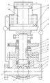
Accompanying drawing 1 is the utility model specific embodiment 1 theory structure sectional view;
Accompanying drawing 2 is the utility model throw over switch specific embodiment stereogram;
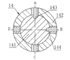
Accompanying drawing 3 is the utility model throw over switch specific embodiment internal structure sectional view;
Accompanying drawing 4 is a throw over switch closed condition structure sectional view;
Accompanying drawing 5 is a throw over switch opening state structure sectional view;
Accompanying drawing 6 is a throw over switch self-locking state structure sectional view;
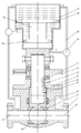
Accompanying drawing 7 is the utility model specific embodiment 2 theory structure sectional views;
Accompanying drawing 8 is the utility model clutch mechanism specific embodiment structure sectional view.
The utility model is described in further detail below in conjunction with accompanying drawing and specific embodiment.
Embodiment
Specific embodiment 1: as shown in Figure 1, liquid formula automatic ball valve still comprises valve body 1, valve gap 9, valve rod 8 and spheroid 2, described spheroid 2 is arranged in the valve pocket of valve body 1, the valve pocket both sides are feeding-passage 4 and tapping channel 6, be provided with valve seat 12 in the valve pocket, described valve rod 8 lower ends are passed valve gap 9 and are entered valve body 1 inner chamber, and the axial motion that is provided with valve rod 8 between described valve rod 8 and the spheroid 2 transfers the driving mechanism that rotatablely moves to, reaches the purpose of open and close valve by spinning ball 2.In this specific embodiment, driving mechanism comprises a tubular pivoted housing 3 of circumferentially fixedlying connected with spheroid 2, described tubular pivoted housing 3 is arranged in the valve pocket rotationally, described valve rod 8 lower ends are inserted in the tubular pivoted housing 3 movingly, described valve rod 8 bottom cylindrical surfaces are provided with the transposition groove that one section helical groove constitutes, described tubular pivoted housing 3 inwall opposite positions are provided with outstanding transposition key 7, described transposition key 7 drops on and constitutes a ramp effect structure in the transposition groove, also be provided with one section direction recess 11 vertically on described valve rod 8 cylinders, opposite position is provided with outstanding feather key 10 on the valve gap 9, described feather key 10 drops on and constitutes an axially directed mechanism in the direction recess 11, and described ramp effect structure and axially directed mechanism constitute described driving mechanism.In order to make transmission even, described liquid formula automatic ball valve generally is advisable with the 2-4 group along circumferentially can evenly being provided with one group of above ramp effect structure and axially directed mechanism.For realizing utilizing pressure medium as power, liquid formula automatic ball valve also is provided with valve rod driving oil cylinder and throw over switch.As Fig. 2, shown in 3, described valve rod driving oil cylinder comprise have two sections internal diameter cross sections small one and large one cylindrical member 19 and be arranged on wherein first piston 18, second piston 20 and piston rod 21, the central axis of two sections inner chambers of valve rod driving oil cylinder preferably overlaps setting, the sectional shape of valve rod driving oil cylinder inner chamber can be circle or polygonal, select circle in this specific embodiment for use, described first piston chamber and the mutual UNICOM of second piston cavity, first piston chamber sectional area is greater than the second piston cavity sectional area, be respectively equipped with the first piston 18 and second piston 20 that match in the first piston chamber and second piston cavity, the difference of the area in the cross section of the first piston 18 and second piston 20 will satisfy under the normal discharge pressure of medium the pressure difference that is produced at first piston 18 and second piston 20 will be enough to actuate valve stem 8 and move up and down, and the first piston 18 and second piston 20 are fixed on and form interlock on the same piston rod 21.Described valve rod driving oil cylinder is arranged on valve body 1 top, the first piston chamber is last, second piston cavity is following, described piston rod 21 1 ends pass with valve rod 8 upper ends from the bottom of second piston cavity and are connected, as shown in Figure 1, three parts have been separated into by the first piston 18 and second piston 20 in the described cylinder cavity: the top, first piston chamber (being the part of opening direction end) that promptly belongs to the first piston chamber fully; Belong to the second piston cavity bottom (being the part of closing direction end) of second piston cavity and the part (being the part of opening direction opposite direction one side of first piston 18) of the first piston chamber between the first piston 18 and second piston 20 and the second piston cavity UNICOM fully.Shown in Fig. 4-6, throw over switch 14 comprises columniform stem stem 141 and cylindrical shell 142, described cylindrical shell 142 liquid are close and be enclosed within outside the stem stem 141 rotationally movingly, described stem stem 141 is provided with liquid inlet joint 22 and draining connector 23, liquid inlet joint 22 and draining connector 23 by hydraulic tube 15 respectively with feeding-passage 4 and tapping channel 6 UNICOMs, described stem stem 141 cylinders are provided with respectively lead channel 143 and the sump pit 144 with liquid inlet joint 22 and draining connector 23 UNICOMs, lead channel 143 and sump pit 144 are provided with vertically, can certainly be inlet opening and outage, described cylindrical shell 142 outer walls be provided with two butt joints of straight-through inner chamber: joint A, joint B and joint C, joint D.Described joint A is corresponding with relative position and the position between inlet opening and outage or lead channel 143 and the sump pit 144 between joint B and joint C and the joint D, and corresponding joint is received on lead channel 143 and the sump pit 144 simultaneously during with assurance throw over switch 14 transition statuses; Described joint A is connected with the top in first piston chamber with joint D, and described joint B is connected with the bottom of second piston cavity, and described joint C is connected with the bottom in first piston chamber.Lead channel 143 and sump pit 144 on the driving oil cylinder of valve rod described in this specific embodiment stem stem 141 be arranged in parallel vertically, phase phase difference 90o distributes on cylinder, described joint A, joint B and joint C, joint D on cylindrical shell 142 mutually phase difference 90o distribute successively.
The working principle of specific embodiment 1 liquid formula automatic ball valve is as follows:
As shown in Figure 1: when the needs Open valve, throw over switch 14 is clockwise rotated 180o makes throw over switch 14 be in opening state, at this moment as shown in Figure 5, when A point B point is in closed condition, the feeding-passage 4 of C point and feed cavity is in on-state, D point and tapping channel 6 UNICOMs of expecting the chamber, have the in-vivo medium of pressure through the first piston chamber between throw over switch 14 and the C point inflow first piston 18 and second piston 20 and the part (being the part of opening direction opposite direction one side of first piston 18) of the second piston cavity UNICOM before being in valve like this, though this moment, second piston 20 was under pressure simultaneously, but because first piston 18 sectional areas are greater than second piston, 20 sectional areas, the discharge pressure of medium on producing on the first piston 18 thrust greater than the downforce that is produced at second piston 20, therefore first piston 18 rises, the liquid on top, first piston chamber (being the part of opening direction end) is after flowing into valve behind D point and the throw over switch 14, the rising of first piston 18 drives on the valve rod 8 and moves, under the acting in conjunction of axially directed mechanism and ramp effect structure, make spheroid 2 half-twists with valve open, finished the breakdown action of valve.After valve enters working state, throw over switch 14 is forwarded to as shown in Figure 5 self-locking state position, and as shown in Figure 6, throw over switch 14 is closed A, joint B and joint C, joint D, cut off the UNICOM of feed cavity, discharging chamber and cylinder cavity, make liquid formula automatic ball valve keep the opening state safe operation.When closing as needs, as shown in Figure 4, throw over switch 14 is changeed closed condition, this moment, D point and C point were closed, equate with downstream pressure before the valve, as shown in Figure 2, the feeding-passage 4 of A point and feed cavity is in on-state, B point and tapping channel 6 UNICOMs of expecting the chamber, have the in-vivo medium of pressure through throw over switch 14 and A point inflow top, first piston chamber (being the part of opening direction end) before being in valve like this, meanwhile, medium enters the second piston cavity bottom (being the part of closing direction end) through throw over switch 14 and B point behind the valve.At this moment Shang Duan liquid is passed piston downwards, the liquid of the lower end push piston that makes progress, because of first piston 18 sectional areas greater than second piston, 20 sectional areas, the following thrust of institute is greater than last thrust, causes to promote piston and move down, after the liquid of lower end fluid cylinder can only flow back to valve along the B point, under the acting in conjunction of axially directed mechanism and ramp effect structure, make 90 ° of spheroid 2 counterrotatings, finish closing of valve, at this moment still throw over switch 14 is forwarded to self-locking position (Fig. 6), valve is in safety shut-off state.
Specific embodiment 2: as shown in Figure 7, valve rod driving oil cylinder in this liquid formula automatic ball valve can also be the turned upside down setting, be that described valve rod driving oil cylinder is arranged on valve body 1 top, second piston cavity is last, the first piston chamber is following, described piston rod 21 1 ends pass with valve rod 8 upper ends from the bottom in first piston chamber and are connected, and have been separated into three parts by the first piston 18 and second piston 20 in the described cylinder cavity: the bottom, first piston chamber (being the part of closing direction end) that promptly belongs to the first piston chamber fully; Belonging to the second piston cavity top (being the part of opening direction end) of second piston cavity and the first piston chamber between the first piston 18 and second piston 20 and the part of the second piston cavity UNICOM fully (is the opening direction of first piston 18
The part of direction one side).Throw over switch 14 described joint C are connected with the bottom in first piston chamber with joint B, described joint D is connected with the top (being the part of opening direction end) of second piston cavity, and described joint A is connected (part that is opening direction direction one side of first piston 18) with the top in first piston chamber.All the other structures are identical with specific embodiment 1.
The working principle of specific embodiment 2 liquid formula automatic ball valves is as follows:
When the needs Open valve, throw over switch 14 is clockwise rotated 180o makes throw over switch 14 be in opening state, at this moment as shown in Figure 5, when A point B point is in closed condition, the feeding-passage 4 of C point and feed cavity is in on-state, D point and tapping channel 6 UNICOMs of expecting the chamber, have the bottom of the in-vivo medium of pressure before being in valve like this through throw over switch 14 and C point inflow first piston chamber, the second piston cavity top (being the part of opening direction end) is through throw over switch 14 and the pressure release of D point, therefore first piston 18 rises, the liquid on the second piston cavity top (being the part of opening direction end) is after flowing into valve behind D point and the throw over switch 14, the rising of first piston 18 drives on the valve rod 8 and moves, under the acting in conjunction of axially directed mechanism and ramp effect structure, make spheroid 2 half-twists with valve open.With valve open, finished the breakdown action of valve.After valve enters working state, throw over switch 14 is forwarded to as shown in Figure 5 self-locking state position, and as shown in Figure 6, throw over switch 14 is closed A, joint B and joint C, joint D, cut off the UNICOM of feed cavity, discharging chamber and cylinder cavity, make liquid formula automatic ball valve keep the opening state safe operation.When closing as needs, as shown in Figure 4, throw over switch 14 is changeed closed condition, this moment, D point and C point were closed, equate with downstream pressure before the valve, the feeding-passage 4 of A point and feed cavity is in on-state, B point and tapping channel 6 UNICOMs of expecting the chamber, have the in-vivo medium of pressure through the first piston chamber between throw over switch 14 and A point inflow one piston and second piston 20 and the part (being the part of opening direction direction one side of first piston 18) of the second piston cavity UNICOM before being in valve like this, meanwhile, the B point is communicated with the bottom in first piston chamber through throw over switch 14, medium enters the second piston cavity bottom (being the part of closing direction end) through throw over switch 14 and B point behind the valve, though this moment, second piston 20 was under pressure simultaneously, but because first piston 18 sectional areas are greater than second piston, 20 sectional areas, the discharge pressure of medium in the following thrust that produces on the first piston 18 greater than thrust on being produced at second piston 20, cause the promotion piston to move down, after the liquid of lower end fluid cylinder can only flow back to valve along the B point, under the acting in conjunction of axially directed mechanism and ramp effect structure, make 90 ° of spheroid 2 counterrotatings, finish closing of valve at last, at this moment still throw over switch 14 is forwarded to self-locking position (Fig. 5), valve is in safety shut-off state.
When termination of pumping, liquid in pipe pressure disappears, and pressure medium is zero in the valve, relies on the interior medium of valve just can not open valve.In order to guarantee also to operate in this case, also be arranged with handwheel on the described valve rod, be provided with clutch mechanism between described handwheel and the valve rod.As shown in Figure 8, clutch mechanism comprises adjusts screw 16 and clutch trapezoidal nut 17, and described clutch trapezoidal nut is arranged on handle center, adjusts screw 16 and radially is provided with.During manually-operable, tighten adjustment screw 16 and make clutch trapezoidal nut 17 close tight valve rod, at this moment throw over switch is rotated on the enable possition, pin rotates handwheel 5, then valve opening.If instead throttle down then rotates to closed position to throw over switch, then the backward rotation handwheel 5, then valve closing.
Claims (7)
1. liquid formula automatic ball valve, comprise valve body, valve gap, valve rod and spheroid, described spheroid is arranged in the valve pocket of valve body, the valve pocket both sides are feeding-passage and tapping channel, be provided with valve seat in the valve pocket, described valve rod lower end is passed valve gap and is entered body cavity, the axial motion that is provided with between described valve rod and the spheroid valve rod transfers the driving mechanism that rotatablely moves to, it is characterized in that: also be provided with valve rod driving oil cylinder and throw over switch, described oil cylinder inside is provided with small one and large one the first piston chamber and second piston cavity of cross section of mutual UNICOM, be respectively equipped with the first piston and second piston in the first piston chamber and second piston cavity, the first piston and second piston are fixed on and form interlock on the same piston rod, described piston rod one end and valve rod upper end are connected, be provided with pipeline through throw over switch and feed cavity and discharging chamber UNICOM by the each several part of first piston and the separation of second piston in the described cylinder cavity, described throw over switch has unlatching, close and three states of self-locking, under opening state, the part of opening direction opposite direction one side of first piston in described throw over switch UNICOM's feed cavity and the cylinder cavity, simultaneously, the part of opening direction end in throw over switch UNICOM discharging chamber and the cylinder cavity; In off position down, the part of opening direction equidirectional one side of first piston in described throw over switch UNICOM's feed cavity and the cylinder cavity, simultaneously, the part of closing direction end in throw over switch UNICOM discharging chamber and the cylinder cavity; Under self-locking state, described throw over switch cuts off the UNICOM of feed cavity, discharging chamber and cylinder cavity.
2. liquid formula automatic ball valve according to claim 1, it is characterized in that: described valve rod driving oil cylinder comprise have two sections internal diameter cross sections small one and large one cylindrical member and be arranged on wherein first piston, second piston and piston rod, the bigger part in cross section is the first piston chamber, the less part in cross section is second piston cavity, described valve rod driving oil cylinder is arranged on the valve body top, the first piston chamber is last, second piston cavity is following, described piston rod one end passes from the bottom of second piston cavity with the valve rod upper end and is connected, described throw over switch comprises a columniform stem stem and cylindrical shell, described cylindrical shell liquid is close and be enclosed within outside the stem stem movingly rotationally, described stem stem is provided with liquid inlet joint and the draining connector with feed cavity and discharging chamber UNICOM, described stem stem cylinder is provided with respectively inlet opening or lead channel and outage or the sump pit with liquid inlet joint and draining connector UNICOM, described cylindrical shell is provided with two butt joints of straight-through inner chamber, joint A, joint B and joint C, joint D, described joint A is corresponding with relative position and the position between inlet opening and outage or lead channel and the sump pit between joint B and joint C and the joint D; Described joint A is connected with the top in first piston chamber with joint D, and described joint B is connected with the bottom of second piston cavity, and described joint C is connected with the bottom in first piston chamber.
3. liquid formula automatic ball valve according to claim 1, it is characterized in that: described valve rod driving oil cylinder comprise have two sections internal diameter cross sections small one and large one cylindrical member and be arranged on wherein first piston, second piston and piston rod, the bigger part in cross section is the first piston chamber, the less part in cross section is second piston cavity, described valve rod driving oil cylinder is arranged on the valve body top, the first piston chamber is following, second piston cavity is last, described piston rod one end passes from the bottom in first piston chamber with the valve rod upper end and is connected, described throw over switch comprises a columniform stem stem and cylindrical shell, described cylindrical shell liquid is close and be enclosed within outside the stem stem movingly rotationally, described stem stem is provided with liquid inlet joint and the draining connector with feed cavity and discharging chamber UNICOM, described stem stem cylinder is provided with respectively inlet opening or lead channel and outage or the sump pit with liquid inlet joint and draining connector UNICOM, described cylindrical shell is provided with two butt joints of straight-through inner chamber, joint A, joint B and joint C, joint D, described joint A is corresponding with relative position and the position between inlet opening and outage or lead channel and the sump pit between joint B and joint C and the joint D; Described joint C is connected with the bottom in first piston chamber with joint B, and described joint D is connected with the top of second piston cavity, and described joint A is connected with the top in first piston chamber.
4. according to claim 2 or 3 described liquid formula automatic ball valves, it is characterized in that: inlet opening on the described valve rod driving oil cylinder stem stem or lead channel and outage or sump pit be arranged in parallel, phase phase difference 90o distributes on cylinder, described joint A, joint B and joint C, joint D on cylindrical shell mutually phase difference 90o distribute successively.
5. according to claim 1 or 2 or 3 described liquid formula automatic ball valves, it is characterized in that: also be arranged with handwheel on the described valve rod, be provided with clutch mechanism between described handwheel and the valve rod.
6. liquid formula automatic ball valve according to claim 1, it is characterized in that: described driving mechanism comprises a tubular pivoted housing of circumferentially fixedlying connected with spheroid, described pivoted housing is arranged in the valve pocket rotationally, described valve rod lower end is inserted in the pivoted housing movingly, described valve rod bottom cylindrical surface is provided with the transposition groove that one section helical groove constitutes, described pivoted housing inwall opposite position is provided with outstanding transposition key, described transposition key drops on and constitutes a ramp effect structure in the transposition groove, also be provided with one section direction recess on the described valve rod cylinder vertically, opposite position is provided with outstanding feather key on the valve gap, described feather key drops on and constitutes an axially directed mechanism in the groove, and described ramp effect structure and axially directed mechanism constitute described driving mechanism.
7. liquid formula automatic ball valve according to claim 6 is characterized in that: described liquid formula automatic ball valve is along circumferentially evenly being provided with one group of above ramp effect structure and axially directed mechanism.
Priority Applications (1)
| Application Number | Priority Date | Filing Date | Title |
|---|---|---|---|
| CN2010206326469U CN201902594U (en) | 2010-11-30 | 2010-11-30 | Hydraulic and automatic ball valve |
Applications Claiming Priority (1)
| Application Number | Priority Date | Filing Date | Title |
|---|---|---|---|
| CN2010206326469U CN201902594U (en) | 2010-11-30 | 2010-11-30 | Hydraulic and automatic ball valve |
Publications (1)
| Publication Number | Publication Date |
|---|---|
| CN201902594U true CN201902594U (en) | 2011-07-20 |
Family
ID=44273187
Family Applications (1)
| Application Number | Title | Priority Date | Filing Date |
|---|---|---|---|
| CN2010206326469U Expired - Fee Related CN201902594U (en) | 2010-11-30 | 2010-11-30 | Hydraulic and automatic ball valve |
Country Status (1)
| Country | Link |
|---|---|
| CN (1) | CN201902594U (en) |
Cited By (1)
| Publication number | Priority date | Publication date | Assignee | Title |
|---|---|---|---|---|
| CN103542121A (en) * | 2012-07-13 | 2014-01-29 | 布雷格菲尼克斯配件设备有限公司 | Cock fitting |
-
2010
- 2010-11-30 CN CN2010206326469U patent/CN201902594U/en not_active Expired - Fee Related
Cited By (2)
| Publication number | Priority date | Publication date | Assignee | Title |
|---|---|---|---|---|
| CN103542121A (en) * | 2012-07-13 | 2014-01-29 | 布雷格菲尼克斯配件设备有限公司 | Cock fitting |
| CN103542121B (en) * | 2012-07-13 | 2015-11-25 | 布雷格菲尼克斯配件设备有限公司 | Stopcock |
Similar Documents
| Publication | Publication Date | Title |
|---|---|---|
| CN104913080A (en) | Non-wear boosting ball valve | |
| CN102011869A (en) | Hydraulic automatic stop valve | |
| CN201916515U (en) | Hydraulic automatic gate valve | |
| CN202823961U (en) | Novel ultrahigh pressure cleaning water gun | |
| CN102434527B (en) | Hydraulic cylinder | |
| CN102003542A (en) | Automatic hydraulic plug valve | |
| CN108036072A (en) | Pneumatic hydraulic seal wear-resistant ball valve | |
| CN203363202U (en) | Piston type stop valve | |
| CN208764356U (en) | A kind of hand liquid-operated flat valve | |
| CN201902594U (en) | Hydraulic and automatic ball valve | |
| CN202901385U (en) | Stop valve with drain valve | |
| CN102003546A (en) | Hydraulic automatic ball valve | |
| CN201866307U (en) | Hydraulic automatic plug valve | |
| CN102003568A (en) | Hydraulic automatic gate valve | |
| CN204878838U (en) | There is not wearing and tearing pressure boost ball valve | |
| CN204878837U (en) | Turbocharging system of pressure boost ball valve and do not have wearing and tearing pressure boost ball valve | |
| CN204878818U (en) | Telescopic sphere rotates case and does not have wearing and tearing pressure boost ball valve | |
| CN102116377B (en) | Water-saving antifreezing device | |
| CN201963907U (en) | Double-shaft double-plate butterfly valve | |
| CN201875267U (en) | Hydraulic automatic stop valve | |
| CN204828784U (en) | Divide water collector terminal accessory | |
| CN217381744U (en) | Remote shutoff monitoring integrated valve | |
| CN201779311U (en) | Antifreezing valve | |
| CN107559443B (en) | It is a kind of to rapidly switch off valve for water pump operation connection | |
| CN206280524U (en) | pneumatic ball valve with automatic sealing function |
Legal Events
| Date | Code | Title | Description |
|---|---|---|---|
| C14 | Grant of patent or utility model | ||
| GR01 | Patent grant | ||
| C17 | Cessation of patent right | ||
| CF01 | Termination of patent right due to non-payment of annual fee |
Granted publication date: 20110720 Termination date: 20121130 |