CN201899378U - Steam valve - Google Patents

Steam valve Download PDF

Info

Publication number
CN201899378U
CN201899378U CN2010206100693U CN201020610069U CN201899378U CN 201899378 U CN201899378 U CN 201899378U CN 2010206100693 U CN2010206100693 U CN 2010206100693U CN 201020610069 U CN201020610069 U CN 201020610069U CN 201899378 U CN201899378 U CN 201899378U
Authority
CN
China
Prior art keywords
valve
button
disk seat
feather
valve gap
Prior art date
Legal status (The legal status is an assumption and is not a legal conclusion. Google has not performed a legal analysis and makes no representation as to the accuracy of the status listed.)
Expired - Lifetime
Application number
CN2010206100693U
Other languages
Chinese (zh)
Inventor
赵波
郑维
张剑峰
刘利东
郑松杰
廖永华
戴尚书
Current Assignee (The listed assignees may be inaccurate. Google has not performed a legal analysis and makes no representation or warranty as to the accuracy of the list.)
Midea Group Co Ltd
Original Assignee
Midea Group
Priority date (The priority date is an assumption and is not a legal conclusion. Google has not performed a legal analysis and makes no representation as to the accuracy of the date listed.)
Filing date
Publication date
Application filed by Midea Group filed Critical Midea Group
Priority to CN2010206100693U priority Critical patent/CN201899378U/en
Application granted granted Critical
Publication of CN201899378U publication Critical patent/CN201899378U/en
Anticipated expiration legal-status Critical
Expired - Lifetime legal-status Critical Current

Links

Images

Abstract

The utility model relates to a steam valve, including valve gap and disk seat, wherein the articulated end of valve gap and disk seat is together articulated, its characterized in that the other end of disk seat is provided with the elasticity valve and detains, corresponds, is provided with the card platform in the border inboard of the other end of valve gap, and the outer end head of elasticity valve is provided with the clip with the mutual lock of card platform. The utility model discloses owing to adopted the other end of disk seat to be provided with elastic valve and detained, utilize valve detain self elasticity to make disk seat and valve gap lock joint structure together, thoroughly optimized the connection structure of disk seat and valve gap, simplified assembly operation greatly, not only reduced the material cost of labor cost, increased substantially production efficiency moreover.

Description

A kind of steam valve
Technical field
The utility model relates to a kind of steam valve, and particularly a kind of steam valve that is used for the electric cooker product belongs to the improvement technology of steam valve.
Background technology
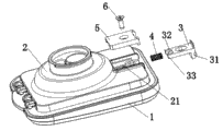
Steam valve structure such as Fig. 1 of existing electric cooker show, comprise valve gap 1, valve seat 2, valve fastener 3 and spring 4, valve gap 1 is hinged with the hinged end of valve seat 2, the inner side edge of valve gap 1 other end is provided with the valve gap grab, the other end of valve seat is provided with valve fastener assembling groove 21, the both sides of the horizontally-guided end of valve fastener are provided with lead 33, be provided with reference column 32 therebetween, the vertical buckling end top of valve fastener is provided with deck 31, spring 4 is sleeved on the reference column 32, pushing valve fastener 3 is installed in the groove 21 it, pressing plate 5 is placed on above the valve fastener 3 again, with screw 6 pressing plate and valve fastener is fixed in the groove 21, the steam valve of said structure is because profile and volume are less, valve fastener 3, spring 4, pressing plate 5 all is more small-sized part, must press...with one's finger during installation to press solidly and reserve the valve fastener, otherwise very easily the spring bullet be flown, not only need instrument to tighten screw, and needing to hold the stable control of erection skill, efficiency of assembling is not high.
Summary of the invention
The purpose of this utility model be to consider the problems referred to above and provide a kind of simple in structure, simple and easy quick, the steam valve that can increase substantially production efficiency is installed.
The technical solution of the utility model is: a kind of steam valve, comprise valve gap and valve seat, wherein the hinged end of valve gap and valve seat is hinged, the other end that it is characterized in that described valve seat is provided with the feather valve button, corresponding, inboard, edge at the other end of valve gap is provided with Ka Tai, and the outer end head of feather valve button is provided with the clasp that fastens mutually with Ka Tai.
Described feather valve button is asymmetrical U-shaped or V-arrangement or corrugated structure, and its medial extremity and outboard end and valve seat are one-body molded, and outboard end is higher than medial extremity and the unsettled design of elasticity.
Described feather valve button bit is in the recess of the other end setting of valve seat, certain interval is arranged for the both sides of feather valve button and recess so that the outboard end elasticity convergent-divergent of feather valve button, and corresponding feather valve is buckled in the edge of the other end of valve gap and is provided with recess so that clasp can enter and fasten mutually with Ka Tai.
The utility model is owing to adopted the other end of valve seat to be provided with the feather valve button, the structure of utilizing valve button self elasticity that valve seat and valve gap are snapped together, thoroughly optimized the syndeton of valve seat and valve gap, simplified assembly manipulation greatly, not only reduce material expenses of labour cost, and increased substantially production efficiency.
Description of drawings
Fig. 1 is the STRUCTURE DECOMPOSITION schematic diagram of prior art steam valve;
Fig. 2 is the structural representation of the utility model steam valve;
Fig. 3 is the longitudinal sectional view of the utility model steam valve at buckling state;
Fig. 4 is the longitudinal sectional view of the utility model steam valve in open mode.
The specific embodiment
Shown in Fig. 2,3,4, the utility model steam valve, comprise valve gap 1 and valve seat 2, wherein valve gap 1 is hinged with the hinged end of valve seat 2, the other end of valve seat 2 is provided with feather valve button 21, corresponding, the inboard, edge of the other end of valve gap 1 is provided with card platform 11, and the outer end head of feather valve button 21 is provided with and blocks the clasp 213 that platform 11 fastens mutually.
In the present embodiment, described feather valve button 21 is asymmetrical U-shaped or V-arrangement or corrugated structure, its medial extremity 211 and outboard end 212 are one-body molded with valve seat 2, outboard end 212 is higher than medial extremity 211 and the unsettled design of elasticity, thereby can produce elastic deformation, clasp 213 is arranged on the head of outboard end 212.Above-mentioned feather valve button 21 is positioned at the recess 214 of the other end setting of valve seat 2, certain interval is arranged for the both sides of feather valve button 21 and recess 214 so that the outboard end of feather valve button 21 212 elasticity convergent-divergents, and corresponding feather valve button 21 is provided with recess 12 so that clasp 213 can enter and fasten mutually with card platform 11 in the edge of the other end of valve gap 1.
The utility model steam valve only need push hard the outboard end 212 of compression elasticity valve button 21 a little when assembling or use, the button bit 213 of feather valve button 21 is snapped in the valve gap grab 11, can realize closing the lid action; The outboard end 212 of pushing feather valve button 21 makes the button bit 213 of feather valve button 21 withdraw from valve gap grab 11, can realize the action of uncapping.The utility model is simple in structure, and cost is low, and assembling process need not to use other instruments, and is convenient and swift, the production efficiency height.

Claims (3)

1. steam valve, comprise valve gap (1) and valve seat (2), wherein valve gap (1) is hinged with the hinged end of valve seat (2), the other end that it is characterized in that described valve seat (2) is provided with feather valve button (21), corresponding, inboard, edge at the other end of valve gap (1) is provided with Ka Tai (11), and the outer end head of feather valve button (21) is provided with the clasp (213) that fastens mutually with Ka Tai (11).
2. steam valve according to claim 1, it is characterized in that described feather valve button (21) is asymmetrical U-shaped or V-arrangement or corrugated structure, its medial extremity (211) and outboard end (212) are one-body molded with valve seat (2), and outboard end (212) is higher than medial extremity (211) and the unsettled design of elasticity.
3. steam valve according to claim 1 and 2, it is characterized in that described feather valve button (21) is positioned at the recess (214) of the other end setting of valve seat (2), certain interval is arranged for the both sides of feather valve button (21) and recess (214) so that outboard end (212) the elasticity convergent-divergent of feather valve button (21), and corresponding feather valve button (21) is provided with recess (12) so that clasp (213) can enter and fasten mutually with Ka Tai (11) in the edge of the other end of valve gap (1).
CN2010206100693U 2010-11-17 2010-11-17 Steam valve Expired - Lifetime CN201899378U (en)

Priority Applications (1)

Application Number Priority Date Filing Date Title
CN2010206100693U CN201899378U (en) 2010-11-17 2010-11-17 Steam valve

Applications Claiming Priority (1)

Application Number Priority Date Filing Date Title
CN2010206100693U CN201899378U (en) 2010-11-17 2010-11-17 Steam valve

Publications (1)

Publication Number Publication Date
CN201899378U true CN201899378U (en) 2011-07-20

Family

ID=44269979

Family Applications (1)

Application Number Title Priority Date Filing Date
CN2010206100693U Expired - Lifetime CN201899378U (en) 2010-11-17 2010-11-17 Steam valve

Country Status (1)

Country Link
CN (1) CN201899378U (en)

Cited By (2)

* Cited by examiner, † Cited by third party
Publication number Priority date Publication date Assignee Title
CN107348837A (en) * 2016-05-09 2017-11-17 佛山市顺德区美的电热电器制造有限公司 A kind of electric cooker steam valve cover-opening structure and electric cooker
CN108433554A (en) * 2017-02-16 2018-08-24 佛山市顺德区美的电热电器制造有限公司 Steam valve cap component and steam valve and cooking utensils

Similar Documents

Publication Publication Date Title
CN101127390B (en) Battery cover structure
CN204596856U (en) Power brick and unmanned plane
CN201899378U (en) Steam valve
CN101871632B (en) Hanging buckle structure
CN201278879Y (en) Watch band fastener
CN101835358B (en) Fastener matching structure and mobile terminal
CN203619487U (en) Steam mop with handle switch
CN201767790U (en) Steam valve
CN203105863U (en) Invisible zipper puller
CN203406213U (en) Elastic button
CN201174201Y (en) Attachable electronic label fixing seat
CN207626698U (en) A kind of connection structure and wrist-watch facilitating watchband and watchcase dismounting
CN201699067U (en) Remote controller back cover opening device
CN207274578U (en) A kind of end cap with interface arrangment
CN202352745U (en) Portable electronic device
CN204102974U (en) A kind of battery cover fastening fixture of electronic lock
CN204256383U (en) The wrist-watch of easy replacing watchband
CN206020861U (en) A kind of display outer frame
CN205682636U (en) A kind of pin-connected panel slider of zipper fastener
CN204077561U (en) A kind of car roof panel mounting structure
CN204233895U (en) A kind of filter cartridge construction
CN201969849U (en) Clamping bolt head
CN202395219U (en) Switch socket connecting device
CN202299754U (en) Flicking structure for automobile trunk lock catch
CN203706023U (en) Tablet personal computer with multifunctional fastener system

Legal Events

Date Code Title Description
C14 Grant of patent or utility model
GR01 Patent grant
C56 Change in the name or address of the patentee

Owner name: MIDEA GROUP CO., LTD.

Free format text: FORMER NAME: MEIDI GROUP CO. LTD.

CP03 Change of name, title or address

Address after: 528311 Guangdong, Foshan, Beijiao, the United States, the United States and the United States on the avenue of the United States, the headquarters of the United States building B floor, District, 26-28

Patentee after: MIDEA GROUP Co.,Ltd.

Address before: 528311 beautiful road, Beijiao Town, Shunde District, Guangdong, Foshan

Patentee before: Midea Group

CX01 Expiry of patent term

Granted publication date: 20110720

CX01 Expiry of patent term