CN201884049U - Gas drainage and outburst prevention system for high-pressure water jet cutting and drilling interlocking coal seams with ultra-long drilled holes - Google Patents
Gas drainage and outburst prevention system for high-pressure water jet cutting and drilling interlocking coal seams with ultra-long drilled holes Download PDFInfo
- Publication number
- CN201884049U CN201884049U CN2010206068819U CN201020606881U CN201884049U CN 201884049 U CN201884049 U CN 201884049U CN 2010206068819 U CN2010206068819 U CN 2010206068819U CN 201020606881 U CN201020606881 U CN 201020606881U CN 201884049 U CN201884049 U CN 201884049U
- Authority
- CN
- China
- Prior art keywords
- hole
- drilling rod
- water
- spring housing
- push rod
- Prior art date
- Legal status (The legal status is an assumption and is not a legal conclusion. Google has not performed a legal analysis and makes no representation as to the accuracy of the status listed.)
- Expired - Fee Related
Links
Images

Abstract
The utility model discloses a gas drainage and outburst prevention system and method for high-pressure water jet cutting and drilling interlocking coal seams with ultra-long drilled holes. The system comprises a drill bit, a pressure sensing valve, a drill stem, a drilling machine, a high and low-pressure water delivery rotation device, a high pressure pump and a water tank, the pressure sensing valve is mounted at the front end of the drill stem, the drill bit is mounted at the front end of the pressure sensing valve, a spray nozzle is mounted on the outer side of the pressure sensing valve, the drilling machine drives the drill stem to rotate, and water in the water tank is delivered to the high and low pressure water delivery rotation device by the aid of the high pressure pump, inputted into the drill stem by the high and low pressure water delivery rotation device and delivered to the pressure sensing valve by the drill stem. During drilling withdrawal, a coal seam is cut by the high pressure water so as to realize drilling-cutting linkage and improve work efficiency. The gas drainage and outburst prevention system is simple and smart in structure, cutting diameter can be longer than 3 meters by the aid of the system, the gas exposure area can be increased to be more than 6 times larger than the traditional gas exposure area, the gas release range is effectively increased to be more than 3 times larger than the traditional gas release range, and the problems of coal mine gas drainage and release outburst are solved.
Description
Technical field
The utility model discloses a kind of coal bed gas drainage and protrusion-dispelling system, and particularly a kind of long drilled holes high-pressure water jet bores interlock coal bed gas drainage and the protrusion-dispelling system of cutting.
Background technology
Coal is the important energy source in people's daily life, plays immeasurable effect in people's productive life.Present coal all is to collect from the colliery, in the process of coal mining, because have gas in this coal seam, so in the process of colliery probing, the extraction of gas and prevent coal and the outstanding etc. of gas just seems particularly important, if can not well carry out gas drainage under suction, then there is production accident hidden danger, cause production accident easily.Therefore, before mining, carrying out gas drainage under suction is necessary work.At present, the gas drainage under suction of adopting usually in the colliery all is to adopt the punching technology to carry out, and promptly gets out a plurality of holes from top to bottom at the place, colliery, gas is distributed in the hole, and the subject matter that this kind way exists, the aperture that is exactly boring is too small, about usually 20cm effect, so just make that effective exposed area is too small, it is too small that gas in the coal seam discharges scope, and, intensive punching, certainly will will increase the punching time, make that production efficiency is low, cost of production is more high.Though, some other gas drainage method was also proposed in the present coal probing research field, as: earlier the hole is accomplished fluently, with in the water diced system patchhole, carry out the water cutting, still again, because subsurface geologic structures complexity, usually when gas drainage under suction, the hole of probing is not straight up and down, but crooked crooked, like this, the water diced system just is difficult for inserting in the hole, usually tens, still can use under 20 meters the drilling depth, the degree of depth when the hole reaches 100-200 rice, even during the degree of depth of hundreds of rice, it is powerless just to seem, tests under the perfect condition so above-mentioned way only rests on, and can't be applied in the actual production; Also the someone proposes another kind of mode, promptly abrasive material is set, after boring reaches set depth, cuts the coal seam by the ejection abrasive material at the drill bit place, reach the purpose of gas drainage under suction, but under this situation, abrasive material can't supply, use inconvenient, therefore, also only rest on conceptual phase, can't be applied in the actual production.
Summary of the invention
In the above-mentioned gas discharge in mine of the prior art system that mentions, the shortcoming that the extraction effect is bad, the utility model provides a kind of new gas drainage method and system, its with hole drill behind desired location, in moving back the process of brill, intermittent ejection water under high pressure is rotated cutting to the coal seam, to enlarge the gas drainage under suction area.
The technical scheme that its technical problem that solves the utility model adopts is: a kind of overlength boring high-pressure water jet bores interlock coal bed gas drainage and the protrusion-dispelling system of cutting, this system comprises drill bit, forced induction valve, drilling rod, rig, high-low pressure water delivery whirligig, high-pressure pump and water tank, forced induction valve is installed in the drilling rod front end, drill bit is installed in the forced induction valve front end, the forced induction valve outside is equipped with nozzle, rig drives drilling rod and rotates, water in the water tank is transferred to high-low pressure water delivery whirligig by high-pressure pump, by high-low pressure water delivery whirligig input drilling rod, arrive the forced induction valve place by drill pipe transmission.
The technical scheme that its technical problem that solves the utility model adopts further comprises:
Described forced induction valve comprises valve body, coupling head, valve pocket, spring housing, spool, push rod and spring, and described valve body is hollow shape, is provided with dividing plate in the middle of the valve body, has main water hole and secondary water hole on the dividing plate, and the valve body side has first hole for water spraying; Described coupling head also is hollow shape, and coupling head and valve body are fixedly installed togather and form a cavity; Described valve pocket is arranged in the cavity that coupling head and valve body form, and is through hole in the middle of the valve pocket, and the valve pocket side has second hole for water spraying, the corresponding setting of second hole for water spraying with first hole for water spraying, and spool is arranged in the valve pocket, and matches with shape of through holes in the valve pocket; Described spring housing also is arranged in the cavity of coupling head and valve body formation, in the middle of the spring housing is cavity, spring is arranged in the spring housing, the corresponding end place with valve pocket of spring housing is provided with end cap, the end cap upper shed through hole and second water channel, through hole cross section on the end cap is less than the cross section of the through hole in the middle of the valve pocket, and the through hole cross section on the end cap is also less than the cross section of the cavity in the middle of the spring housing; Described push rod comprises bar head and the support bar that links together, the bar head of push rod is arranged in the spring housing, the support bar of push rod is inserted in the through hole on the spring housing end cap, and contact with spool, cavity cross section shape in the bar head shape of cross section of push rod and the spring housing matches, and the support bar shape of cross section of push rod and the through hole shape of cross section on the spring housing end cap match; Form first reservoir chamber between described spool and the spring housing end cap, valve pocket has first water channel that is communicated with the secondary water hole and first reservoir chamber, and when spring was extruded, first water channel can be blocked by spool; Form second reservoir chamber between the bar head of described push rod and the spring housing end cap, second water channel is communicated with first reservoir chamber and second reservoir chamber; Form the 3rd reservoir chamber between the bar head of described push rod and the spring housing, have the 3rd water channel that connection second reservoir chamber closes the 3rd reservoir chamber on the bar head of push rod; Described spring is arranged in the 3rd reservoir chamber, and promotes the bar head of push rod.
Described spring housing interior forward end is equipped with regulator bolts, has weep hole in the middle of the regulator bolts, and spring one end props up the bar head of push rod, and the other end props up regulator bolts.
Described regulator bolts inside is provided with first limiting stand, and spring housing is contained on first limiting stand.
Described coupling head side has locating hole corresponding to the regulator bolts place, is provided with dog screw in the locating hole.
Be installed with nozzle in first hole for water spraying in the described valve body outside.
The nose of described push rod is provided with second limiting stand, and spring housing is contained on second limiting stand.
Have tank in the middle of described second limiting stand, second water channel is inclined, is communicated with the tank and first reservoir chamber.
The described valve pocket outside has first seal groove, and first seal groove is respectively arranged with one in both sides before and after second hole for water spraying, one first sealing ring is set in each first seal groove.
Have the 4th reservoir chamber corresponding to dividing plate one end on the described valve pocket.
The described valve pocket outside has second seal groove corresponding to spring housing one end, is provided with second sealing ring in second seal groove.Described drilling rod adopts the multistage drilling rod to be formed by connecting, soft sealing structure between the adjacent drill pipes comprises drilling rod male end and drilling rod female end, drilling rod male end and drilling rod female end are hollow structure, the drilling rod male end is provided with the connector of truncated cone-shaped, the truncated cone-shaped connector is provided with tapered thread, have the link slot that matches with the connector shape on the drilling rod female end, be provided with tapered thread in the link slot, the connector front end is fixed with the positioning head of annulus cylindricality, the link slot bottom has the locating slot that matches with the positioning head shape, is set with sealing ring on the positioning head.
Have two the 3rd seal grooves on the described positioning head, be provided with one the 3rd sealing ring in each the 3rd seal groove.
Described positioning head and locating slot are matched in clearance, and the gap width between positioning head and the locating slot is between the 0.04MM-0.1MM.
Gap width between described positioning head and the locating slot is 0.06MM.
Have seal groove on the described positioning head, sealing ring is arranged in the seal groove.
The described seal groove degree of depth is between the 1.99-2.025MM, and the seal ring coil cross-sectional diameter is between the 2.5-2.6MM.
The described seal groove degree of depth is 2MM, and the seal ring coil cross-sectional diameter is 2.6MM.
Described positioning head length is 25MM.
Screw thread on the described connector is an external screw thread, and the screw thread on the link slot is an internal thread.
The beneficial effects of the utility model are: the utility model is simple in structure, structure is ingenious, and the utility model cuts the coal seam by water under high pressure in moving back the brill process, realizes boring and cuts interlock.Use the utility model, cutting diameter is reached more than 3 meters, thereby can increase the gas exposed area reach in the tradition more than 6 times, effectively increasing gas release scope reaches more than 3 times, simultaneously can also effectively discharge gas pressure and coal seam stress in the coal seam, improve coal bed gas drainage efficient, make that the problem of for many years gas outstanding problem of puzzlement colliery, this coal bed gas drainage overlong time, colliery debalance of preparation and winning work is effectively alleviated.Simultaneously, the utility model can significantly reduce the quantity of boring, and production efficiency is improved, and reduces production costs.
Below in conjunction with the drawings and specific embodiments the utility model is described further.
Description of drawings
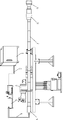
Fig. 1 is the utility model system construction drawing.
Fig. 2 is a gas drainage under suction perforation structure schematic diagram in the prior art.
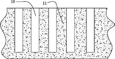
Fig. 3 is a gas drainage under suction perforation structure schematic diagram in the utility model.
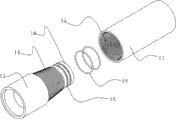
Fig. 4 is the soft sealing structure decomposing state structural representation between drilling rod and the drilling rod in the utility model.
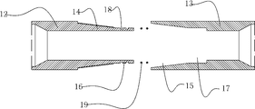
Fig. 5 is the soft sealing structure cross-sectional view between drilling rod and the drilling rod in the utility model.
Fig. 6 is the soft sealing structure decomposing state cross-sectional view between drilling rod and the drilling rod in the utility model.
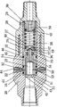
Fig. 7 is a forced induction valve cross-sectional view in the utility model.
Among the figure, 1-water tank, 2-water pipe, 3-high-pressure pump, the 4-high-voltage tube, 5-rig, 6-high-low pressure water delivery whirligig, 7-drilling rod, the 8-forced induction valve, 9-drill bit, 10-hole, 11-stratum, 12-drilling rod male end, 13-drilling rod female end, 14-connector, 15-link slot, the 16-positioning head, 17-locating slot, 18-the 3rd seal groove, 19-the 3rd sealing ring, the 20-valve body, 21-first sealing ring, 22-nozzle, 23-spool, the 24-valve pocket, 25-spring housing, 26-push rod, 27-spring, the 28-coupling head, 29-dog screw, 30-regulator bolts, 31-the 4th reservoir chamber, 32-first water channel, 33-second hole for water spraying, 34-first reservoir chamber, 35-second water channel, 36-second reservoir chamber, 37-the 3rd water channel, 38-the 3rd reservoir chamber, 39-weep hole, 40-first limiting stand, 41-master water hole, the secondary water hole of 42-, 43-first seal groove, 44-first hole for water spraying, 45-second seal groove, 46-second sealing ring, 47-tank, 48-second limiting stand, 49-bar head, 50-support bar, 51-dividing plate.
The specific embodiment
Present embodiment is the utility model preferred implementation, and other all its principles are identical with present embodiment or approximate with basic structure, all within the utility model protection domain.
Please referring to accompanying drawing 1, system of the present utility model mainly comprises drill bit 9, forced induction valve 8, drilling rod 7, rig 5, high-low pressure water delivery whirligig 6, high-pressure pump 4 and water tank 1, in the present embodiment, forced induction valve 8 is installed in drilling rod 7 front ends, forced induction valve 8 can be realized automatic size adjustment water outlet direction and flow according to hydraulic pressure, when low pressure, spray water with high pressure hole 22 by shutoff, water flows out from the low pressure delivery hole, and this moment, the main purpose of low-pressure water was in the drilling process drill bit 9 to be lowered the temperature and deslagging; When the pressure of water increases to certain pressure, forced induction valve 8 automatic shutoff low pressure delivery holes, water can only eject by 22 places, hole that spray water with high pressure, to reach the purpose of cutting hard material.Please referring to accompanying drawing 7, present embodiment mainly comprises valve body 20, coupling head 28, valve pocket 24, spring housing 25, spool 23, push rod 26 and spring 27, and valve body 20 and coupling head 28 are installed together, and forms the present embodiment main body, in the present embodiment, valve body 20 and coupling head 28 are by being threaded togather.In the present embodiment, valve body 20 is hollow shape, is provided with dividing plate 51 (dividing plate 51 is wholely set with valve body 20) in the middle of the valve body 20, has main water hole 41 and secondary water hole 42 on the dividing plate 51, and wherein, main water hole 41 is opened in dividing plate 51 centre positions.In the present embodiment, valve body 20 rear ends have internal thread, are used for being connected with drilling rod.In the present embodiment, valve body 20 sides have in first hole for water spraying, 44, the first hole for water sprayings 44 and are installed with nozzle 22, be used for the water under high pressure ejection, and the cutting coal seam, in the present embodiment, valve body 20 sides have two first hole for water sprayings 44.In the present embodiment, coupling head 28 also is hollow shape, and coupling head 28 is fixedly installed togather with valve body 20 and forms a cavity, and valve pocket 24 and spring housing 25 are arranged in the cavity.In the present embodiment, valve pocket 24 is hollow cylinder, have columniform through hole in the valve pocket 24, spool 23 is arranged in the valve pocket 24, in the present embodiment, spool 23 is also cylindrical, and the diameter of the cross-sectional diameter of spool 23 and valve pocket 24 inner via holes matches, and spool 23 just can be slided in valve pocket 24.In the present embodiment, valve pocket 24 sides have first hole for water spraying, the 44 corresponding settings on second hole for water spraying, 33, the second hole for water sprayings 33 and the valve body 20, can make water by valve pocket 24 sides second hole for water spraying 33 and be arranged on nozzles 22 ejections in first hole for water spraying 44.In the present embodiment, also be hollow-core construction in the middle of the spring housing 25, spring housing 25 main bodys are cylindrical, and inner through hole is also cylindrical.The end that spring housing 25 is connected with valve pocket 24 is provided with end cap (end cap and spring housing 25 are for being wholely set), have through hole in the middle of the end cap, the through hole next door has more than one the 3rd water channel 37, in the present embodiment, the through-hole diameter of end caps is less than the diameter of the through hole in the valve pocket 24, also less than the diameter of the through hole in the spring housing 25.Push rod 26 is arranged in the spring housing 25, in the present embodiment, push rod 26 comprises bar head 49 and the support bar 50 that links together, the bar head 49 of push rod 26 is arranged in the spring housing 25, the support bar 50 of push rod 26 is inserted in the through hole on spring housing 25 end caps, and stretch in the valve pocket 24 and and contact with spool 23, the shape of cross section of the through hole in bar head 49 shape of cross sections of push rod 26 and the spring housing 25 matches, and support bar 50 shape of cross sections of push rod 26 and the through hole shape of cross section on spring housing 25 end caps match.In the present embodiment, bar head 49 front ends of push rod 26 are set with second limiting stand 48.In the present embodiment, spring housing 25 front end inside are provided with internal thread, spring housing 25 front ends are equipped with regulator bolts 30 by screw thread, position corresponding to regulator bolts 30 on coupling head 28 and the spring housing 25 has screw hole, be provided with dog screw 29 in the screw hole, can be by dog screw 29 with the fixed-site of spring housing 25 with coupling head 28.In the present embodiment, regulator bolts 30 is provided with first limiting stand 40, and spring 27 is arranged in the spring housing 25, and spring 27 1 ends are sleeved on first limiting stand 40, and spring 27 other ends are sleeved on second limiting stand 48.
In the present embodiment, form first reservoir chamber 34 between the end cap of spool 23 and spring housing 25, valve pocket 24 is hindered first water channel 32 that has the secondary water hole 42 of connection and first reservoir chamber 34; Form second reservoir chamber 36 between the bar head 49 of push rod 26 and spring housing 25 end caps, have second water channel, 35, the second water channels 35 on spring housing 25 end caps and be communicated with first reservoir chamber 34 and second reservoir chamber 36; Form the 3rd reservoir chamber 38 between the bar head 49 of push rod 26 and the spring housing 25, have the 3rd water channel 37 on the bar head 49 of push rod 26, in the present embodiment, second limiting stand 48 of bar head 49 is provided with tank 47, tank 47 is communicated with the 3rd reservoir chamber 38, the 3rd water channel 37 is obliquely installed, and the 3rd water channel 37 is communicated with the tank 47 and second reservoir chamber 36; In the present embodiment, also offer a cannelure in valve pocket 24 rear ends, form the 4th reservoir chamber 31 between valve pocket 24 and the valve body 20, the secondary water hole 42 and first water channel 32 are communicated with the 4th reservoir chamber 31 respectively, by the 4th reservoir chamber 31 installation between valve pocket 24 and the valve body 20 are more prone to.
In the present embodiment, drill bit 9 is installed in forced induction valve 8 front ends, is used to creep into, and rig 5 drives drilling rod 7 and rotates, and drives forced induction valve 8 and drill bit 9 rotations by drilling rod 7.In the water tank 1 clear water is housed, water in the water tank 1 transfers to high-pressure pump 3 by water pipe 2, after pressurizeing, 3 pairs of water of high-pressure pump are transferred to high-low pressure water delivery whirligig 6 by high-voltage tube 4, high-low pressure water delivery whirligig 6 can realize making the water in the high-voltage tube 4 to change rotation status into by inactive state, and can guarantee simultaneously to seal constant with pressure, in the present embodiment, the high-low pressure water delivery whirligig of the model P8P8 that the StoneAge company of the high-low pressure water delivery whirligig 6 employing U.S. produces.By high-low pressure water delivery whirligig 6 water is imported drilling rod 7, water is transferred to forced induction valve 8 places by drilling rod 7.In the utility model, drilling rod 7 adopts hollow drill, and, drilling rod 7 adopts the multistage drilling rod to be formed by connecting, the length of common one section drilling rod 7 is about about 700mm-1500mm, can feed water under high pressure in the drilling rod 7, and remain under the state of high pressure, junction between the adjacent drill pipes can not produce phenomenons such as seepage, in the present embodiment, soft sealing structure between drilling rod and the drilling rod has been done particular design, please referring to accompanying drawing 4 to accompanying drawing 6, the junction between the utility model drilling rod and the drilling rod mainly comprises drilling rod male end 12 and drilling rod female end 13, during concrete production, an end that generally is a drilling rod 7 is a drilling rod male end 12, and the other end is a drilling rod female end 13, also can be designed to two ends and be the special drill pipe that drilling rod male end 12 or two ends are drilling rod female end 13.During use, drilling rod male end 12 is inserted use in the drilling rod female end 13.In the present embodiment, drilling rod male end 12 front ends are the connector 14 of a truncated cone-shaped, connector 14 front ends are fixed with columniform positioning head 16, because drilling rod is a hollow stem, so, connector 14 is actually hollow truncated cone-shaped, and positioning head 16 actual cross sections are annular, and positioning head 16 is the annulus cylindricality.In the present embodiment, drilling rod female end 13 front ends are the link slot 15 of a truncated cone-shaped, and the shape of link slot 15 and connector 14 shapes match, and link slot 15 rears are columniform locating slot 17, and the shape of locating slot 17 and positioning head 16 shapes match.In the present embodiment, connector 14 outsides are provided with tapered thread, the screw thread of connector 14 outsides is an external screw thread, link slot 15 be provided with connector 14 on the corresponding tapered thread of screw thread, screw thread on the link slot 15 is an internal thread, during use, can be fixedly installed togather by the screw thread at connector 14 and link slot 15 places between two drilling rods.Positioning head 16 in the present embodiment is plugged on locating slot 17, positioning head 16 adopts matched in clearance with locating slot 17,6 gap width of positioning head 16 and locating slot is between the 0.04MM-0.1MM, be preferably 0.06MM, positioning head 16 length in the present embodiment are 25MM, and the present invention adopts special structural design, both can guarantee under the situation of certain camber, the disconnection phenomenon can be do not produced between drilling rod and the drilling rod, the sealing between drilling rod and the drilling rod can be guaranteed again.In order further to guarantee the sealing between drilling rod and the drilling rod, on positioning head 16, have the 3rd seal groove 18, in the present embodiment, have two article of the 3rd seal groove 18 on the positioning head 16, be provided with one the 3rd sealing ring 19 in each the 3rd seal groove 18, the 3rd seal groove 18 degree of depth in the present embodiment are between the 1.99MM-2.025MM, be preferably 2MM, the cross-sectional diameter of the circle body of the 3rd sealing ring 19 is between the 2.5MM-2.6MM, be preferably 2.6MM, see through the 3rd sealing ring 19 is set on positioning head 16, can further guarantee the sealing between drilling rod and the drilling rod, it can not produced under the high pressure of 70MPa leak, phenomenons such as infiltration.The 3rd sealing ring 19 in the present embodiment can adopt multiple form of structure such as O type circle, Y-shaped ring or drum type circle.Adopt the truncated cone-shaped syndeton between drilling rod in the utility model and the drilling rod, and on the truncated cone-shaped syndeton, be provided with tapered thread, guaranteed the fastness that is connected between drilling rod and the drilling rod, the utility model is provided with the positioning head of annular at the connector front end, adopt matched in clearance between positioning head and the locating slot, both can guarantee under the situation of certain camber, can not produce the disconnection phenomenon between drilling rod and the drilling rod, can guarantee the sealing between drilling rod and the drilling rod again, simultaneously, the utility model also has seal groove on positioning head, be provided with sealing ring in the seal groove, can further guarantee the sealing between drilling rod and the drilling rod, guarantee that it can not produce to leak under the condition of 70MPa, the infiltration phenomenon.
The utility model comprises the steps: in use
A, rig drive drilling rod and rotate, and drilling rod drives drill bit and rotates, and holes, and in the present embodiment, during boring, high-pressure pump 3 injects hydraulic pressure pressure in drilling rod 7 be the 2MPa-10MPa low-pressure water, and low-pressure water flows out from forced induction valve 8 front ends, and drill bit 9 is lowered the temperature;
B, be bored into set depth after, injecting hydraulic pressure pressure by high-pressure pump 3 in drilling rod 7 is the 30MPa-70MPa water under high pressure, water under high pressure sprays from forced induction valve 8 sides, simultaneously, rig 5 drives drilling rod 7 and rotates, and drilling rod 7 drives forced induction valve 8 and rotates, the water under high pressure of forced induction valve 8 ejections is rotated cutting to the coal seam, during cutting, the direction of rotation of the direction of rotation of drilling rod 7 when advancing to bore is consistent, makes between drilling rod and the drilling rod can not disconnect;
Are set at C, clipping time 2min-5min or cut radius when reaching the degree of depth (deciding as the case may be) of 0.5m-3.5m, high-pressure pump 5 stops to inject water under high pressure in drilling rod 7, stop the coal seam being rotated cutting, rig 5 drives drilling rod 7 and rotates, drilling rod 7 drives forced induction valve 8 and drill bit 9 retreats, when retreating, the direction of rotation of the direction of rotation of drilling rod 7 when advancing to bore is consistent, makes between drilling rod and the drilling rod can not disconnect;
After D, drill bit retreated preseting length, generally, it was between 0.2 meter-3 meters (deciding as the case may be) that each drill bit retreats length, whenever retreats drill bit 9 one time, then repeats step B one time;
E, repeating step C and step D then retreat to the degree of depth that does not need to cut until drill bit, and rig drives drilling rod and rotates, and drilling rod drives forced induction valve and drill bit retreats, and withdraws from, and promptly finishes.
The utility model utilizes high-pressure pump 3 that hydraulic pressure is gone in the forced induction valve 8 in use, and the utility model is divided into two kinds of high pressure and two kinds of user modes of low pressure.When the utility model is operated in low-pressure state, high-pressure pump 3 provides pressure to be about the low-pressure water of 2MPa-10MPa, spring 27 is extended state, and at this moment, spool 23 blocks second hole for water spraying 33, expose first water channel 32, low-pressure water flows in first reservoir chamber 34 from secondary water hole 42 through first water channel 32, flows in second reservoir chamber 36 through second water channel 35 again, flows in the 3rd reservoir chamber 38 through the 3rd water channel 37 then, flow out through weep hole 39 again, drill bit is cooled off; As low pressure when high pressure conditions is changed, high-pressure pump 3 provides pressure to be about the water under high pressure of 30MPa-70MPa, water under high pressure is not prompt enough when first water channel 32 flows through, at this moment, water under high pressure promotes spool 23 and travels forward, spool 23 promotes push rod 26, push rod 26 extrusion springs 27, make spring 27 compressions, when spool 23 moved to a certain degree, spool 23 blocked first water channel 32, and exposes second hole for water spraying 33, water is sprayed in the side through nozzle 22 from second hole for water spraying 33, realize the purpose in cutting coal seam.The utility model can be regulated the pressure of the utility model conversion by regulating regulator bolts 30, during adjusting in use, unclamp dog screw 29 earlier, then by turn-knob regulator bolts 30, when regulator bolts 30 forward during turn-knob, switching to pressure of the present utility model reduces; When regulator bolts 30 backward during turn-knob, switching to pressure of the present utility model raises.
The utility model is simple in structure, structure is ingenious, use the utility model, cutting diameter is reached more than 3 meters, thereby can increase the gas exposed area reach in the tradition more than 6 times, effectively increasing gas release scope reaches more than 3 times, simultaneously can also effectively discharge gas pressure and coal seam stress in the coal seam, improve coal bed gas drainage efficient, make that the problem of for many years gas outstanding problem of puzzlement colliery, this coal bed gas drainage overlong time, colliery debalance of preparation and winning work is effectively alleviated.Simultaneously, the utility model can significantly reduce the quantity of boring, and production efficiency is improved, and reduces production costs.Simultaneously, in the cut place owing under the effect of coal seam self stress, also can make the coal seam produce the nature fracture, more XXL the exposure and the extraction area of gas.
Claims (6)
1. an overlength boring high-pressure water jet bores interlock coal bed gas drainage and the protrusion-dispelling system of cutting, it is characterized in that: described system comprises drill bit, forced induction valve, drilling rod, rig, high-low pressure water delivery whirligig, high-pressure pump and water tank, forced induction valve is installed in the drilling rod front end, drill bit is installed in the forced induction valve front end, the forced induction valve outside is equipped with nozzle, rig drives drilling rod and rotates, water in the water tank is transferred to high-low pressure water delivery whirligig by high-pressure pump, by high-low pressure water delivery whirligig input drilling rod, arrive the forced induction valve place by drill pipe transmission.
2. overlength boring high-pressure water jet according to claim 1 bores interlock coal bed gas drainage and the protrusion-dispelling system of cutting, it is characterized in that: described forced induction valve comprises valve body, coupling head, valve pocket, spring housing, spool, push rod and spring, described valve body is hollow shape, be provided with dividing plate in the middle of the valve body, have main water hole and secondary water hole on the dividing plate, the valve body side has first hole for water spraying; Described coupling head also is hollow shape, and coupling head and valve body are fixedly installed togather and form a cavity; Described valve pocket is arranged in the cavity that coupling head and valve body form, and is through hole in the middle of the valve pocket, and the valve pocket side has second hole for water spraying, the corresponding setting of second hole for water spraying with first hole for water spraying, and spool is arranged in the valve pocket, and matches with shape of through holes in the valve pocket; Described spring housing also is arranged in the cavity of coupling head and valve body formation, in the middle of the spring housing is cavity, spring is arranged in the spring housing, the corresponding end place with valve pocket of spring housing is provided with end cap, the end cap upper shed through hole and second water channel, through hole cross section on the end cap is less than the cross section of the through hole in the middle of the valve pocket, and the through hole cross section on the end cap is also less than the cross section of the cavity in the middle of the spring housing; Described push rod comprises bar head and the support bar that links together, the bar head of push rod is arranged in the spring housing, the support bar of push rod is inserted in the through hole on the spring housing end cap, and contact with spool, cavity cross section shape in the bar head shape of cross section of push rod and the spring housing matches, and the support bar shape of cross section of push rod and the through hole shape of cross section on the spring housing end cap match; Form first reservoir chamber between described spool and the spring housing end cap, valve pocket has first water channel that is communicated with the secondary water hole and first reservoir chamber, and when spring was extruded, first water channel can be blocked by spool; Form second reservoir chamber between the bar head of described push rod and the spring housing end cap, second water channel is communicated with first reservoir chamber and second reservoir chamber; Form the 3rd reservoir chamber between the bar head of described push rod and the spring housing, have the 3rd water channel that connection second reservoir chamber closes the 3rd reservoir chamber on the bar head of push rod; Described spring is arranged in the 3rd reservoir chamber, and promotes the bar head of push rod.
3. overlength boring high-pressure water jet according to claim 2 bores interlock coal bed gas drainage and the protrusion-dispelling system of cutting, it is characterized in that: described spring housing interior forward end is equipped with regulator bolts, have weep hole in the middle of the regulator bolts, spring one end props up the bar head of push rod, and the other end props up regulator bolts.
4. overlength boring high-pressure water jet according to claim 3 bores and cuts interlock coal bed gas drainage and protrusion-dispelling system, and it is characterized in that: described coupling head side has locating hole corresponding to the regulator bolts place, is provided with dog screw in the locating hole.
5. bore interlock coal bed gas drainage and the protrusion-dispelling system of cutting according to any described overlength boring high-pressure water jet in the claim 1 to 4, it is characterized in that: described drilling rod adopts the multistage drilling rod to be formed by connecting, soft sealing structure between the adjacent drill pipes comprises drilling rod male end and drilling rod female end, drilling rod male end and drilling rod female end are hollow structure, the drilling rod male end is provided with the connector of truncated cone-shaped, the truncated cone-shaped connector is provided with tapered thread, have the link slot that matches with the connector shape on the drilling rod female end, be provided with tapered thread in the link slot, the connector front end is fixed with the positioning head of annulus cylindricality, the link slot bottom has the locating slot that matches with the positioning head shape, is set with sealing ring on the positioning head.
6. overlength boring high-pressure water jet according to claim 5 bores and cuts interlock coal bed gas drainage and protrusion-dispelling system, it is characterized in that: have two the 3rd seal grooves on the described positioning head, be provided with one the 3rd sealing ring in each the 3rd seal groove.
Priority Applications (1)
| Application Number | Priority Date | Filing Date | Title |
|---|---|---|---|
| CN2010206068819U CN201884049U (en) | 2010-11-15 | 2010-11-15 | Gas drainage and outburst prevention system for high-pressure water jet cutting and drilling interlocking coal seams with ultra-long drilled holes |
Applications Claiming Priority (1)
| Application Number | Priority Date | Filing Date | Title |
|---|---|---|---|
| CN2010206068819U CN201884049U (en) | 2010-11-15 | 2010-11-15 | Gas drainage and outburst prevention system for high-pressure water jet cutting and drilling interlocking coal seams with ultra-long drilled holes |
Publications (1)
| Publication Number | Publication Date |
|---|---|
| CN201884049U true CN201884049U (en) | 2011-06-29 |
Family
ID=44181589
Family Applications (1)
| Application Number | Title | Priority Date | Filing Date |
|---|---|---|---|
| CN2010206068819U Expired - Fee Related CN201884049U (en) | 2010-11-15 | 2010-11-15 | Gas drainage and outburst prevention system for high-pressure water jet cutting and drilling interlocking coal seams with ultra-long drilled holes |
Country Status (1)
| Country | Link |
|---|---|
| CN (1) | CN201884049U (en) |
Cited By (7)
| Publication number | Priority date | Publication date | Assignee | Title |
|---|---|---|---|---|
| CN102352725A (en) * | 2011-09-22 | 2012-02-15 | 中国矿业大学 | Drilling jet type coal seam cutting system |
| CN102465712A (en) * | 2010-11-15 | 2012-05-23 | 湖南汉寿中煤科技有限公司 | Drilling-cutting-linked coal layer gas drainage and outburst prevention system and method based on ultra-long drilling and high-pressure water jetting |
| CN102587961A (en) * | 2012-04-10 | 2012-07-18 | 中国矿业大学 | Feeding method and device for hole protecting pipe for soft coal seam gas extraction hole |
| CN103032024A (en) * | 2011-10-09 | 2013-04-10 | 湖南汉寿煤矿机械有限公司 | Mining continuous drilling machine |
| CN103075180A (en) * | 2013-01-15 | 2013-05-01 | 中国矿业大学 | Gas-liquid two-phase jet slotting system and method |
| CN103104222A (en) * | 2013-02-01 | 2013-05-15 | 中北大学 | Method for pumping and collecting coal bed gas through combination of ground vertical well and long bedding drill hole |
| CN105909228A (en) * | 2016-06-29 | 2016-08-31 | 中国矿业大学(北京) | Pulse high-pressure hydraulic slotting and fracturing device and method |
-
2010
- 2010-11-15 CN CN2010206068819U patent/CN201884049U/en not_active Expired - Fee Related
Cited By (13)
| Publication number | Priority date | Publication date | Assignee | Title |
|---|---|---|---|---|
| CN102465712A (en) * | 2010-11-15 | 2012-05-23 | 湖南汉寿中煤科技有限公司 | Drilling-cutting-linked coal layer gas drainage and outburst prevention system and method based on ultra-long drilling and high-pressure water jetting |
| CN102465712B (en) * | 2010-11-15 | 2015-01-28 | 湖南汉寿中煤科技有限公司 | Drilling-cutting-linked coal layer gas drainage and outburst prevention system and method based on ultra-long drilling and high-pressure water jetting |
| CN102352725B (en) * | 2011-09-22 | 2013-07-17 | 中国矿业大学 | Drilling jet type coal seam cutting system |
| CN102352725A (en) * | 2011-09-22 | 2012-02-15 | 中国矿业大学 | Drilling jet type coal seam cutting system |
| CN103032024A (en) * | 2011-10-09 | 2013-04-10 | 湖南汉寿煤矿机械有限公司 | Mining continuous drilling machine |
| CN103032024B (en) * | 2011-10-09 | 2016-08-24 | 湖南汉寿煤矿机械有限公司 | Mining continuous drilling machine |
| CN102587961A (en) * | 2012-04-10 | 2012-07-18 | 中国矿业大学 | Feeding method and device for hole protecting pipe for soft coal seam gas extraction hole |
| CN103075180A (en) * | 2013-01-15 | 2013-05-01 | 中国矿业大学 | Gas-liquid two-phase jet slotting system and method |
| CN103075180B (en) * | 2013-01-15 | 2014-12-10 | 中国矿业大学 | Gas-liquid two-phase jet slotting system and method |
| CN103104222A (en) * | 2013-02-01 | 2013-05-15 | 中北大学 | Method for pumping and collecting coal bed gas through combination of ground vertical well and long bedding drill hole |
| CN103104222B (en) * | 2013-02-01 | 2015-07-29 | 中北大学 | Ground peupendicular hole combines extraction coal bed gas method with concordant long drilled holes |
| CN105909228A (en) * | 2016-06-29 | 2016-08-31 | 中国矿业大学(北京) | Pulse high-pressure hydraulic slotting and fracturing device and method |
| CN105909228B (en) * | 2016-06-29 | 2018-10-09 | 中国矿业大学(北京) | High voltage pulse hydraulic slotted liner technique-fracturing device and method |
Similar Documents
| Publication | Publication Date | Title |
|---|---|---|
| CN102465712B (en) | Drilling-cutting-linked coal layer gas drainage and outburst prevention system and method based on ultra-long drilling and high-pressure water jetting | |
| CN201884049U (en) | Gas drainage and outburst prevention system for high-pressure water jet cutting and drilling interlocking coal seams with ultra-long drilled holes | |
| CN103306657B (en) | A kind of coal seam cutting release is anti-reflection and slot holding device and method | |
| CN108547604B (en) | Drilling and stamping integrated device and method | |
| CN102536185B (en) | Multi-stage draggable water-jet packer tubular column and technology | |
| CN203308447U (en) | Intelligent electric switch sliding sleeve | |
| CN105239983A (en) | Low-gas permeability coal seam weakening and permeability increasing method combining presplitting and high-pressure water injection | |
| CN203499569U (en) | Water-pressure-controlled drilling and blanking integrated efficient drill bit | |
| CN101586470B (en) | Advanced drilling method for high-pressure water-rich filling cavity | |
| CN105089499A (en) | Coal mine downhole hydraulic jet tree-shaped drill hole guide device and method | |
| CN103075180A (en) | Gas-liquid two-phase jet slotting system and method | |
| CN203547562U (en) | Integrated drilling and cutting drill stem | |
| CN208416512U (en) | A kind of brill punching press integrated apparatus | |
| CN103643899A (en) | Integrated drilling-cutting drill rod device | |
| CN103573193B (en) | Integration is bored and is cut boring rod set | |
| WO2019205472A1 (en) | Controllable pressure injection apparatus based on hydraulic accumulator and method therefor | |
| CN109630076A (en) | A kind of method of radially horizontal well and decompression heat injection unitized production gas hydrates | |
| CN103485721A (en) | High-low-pressure hydraulic hole flushing switcher | |
| CN112855022A (en) | Directional long drilling and punching integrated device and method | |
| CN203035094U (en) | Water jet flow kerf induced spraying device in drill hole | |
| CN103437742A (en) | Sand-replenishing tool for rapidly opening and closing filling channel | |
| CN102465684B (en) | Pressure induction valve | |
| CN115822543A (en) | Coal seam ultrasonic activation staged fracturing device and method | |
| CN203230377U (en) | Ball pitching type rapid drillable bridge plug | |
| CN108071376B (en) | Injection and production string in coal-bed gas well |
Legal Events
| Date | Code | Title | Description |
|---|---|---|---|
| C14 | Grant of patent or utility model | ||
| GR01 | Patent grant | ||
| CF01 | Termination of patent right due to non-payment of annual fee | ||
| CF01 | Termination of patent right due to non-payment of annual fee |
Granted publication date: 20110629 Termination date: 20161115 |