CN201879086U - Detachable multi-functional commodity shelf - Google Patents
Detachable multi-functional commodity shelf Download PDFInfo
- Publication number
- CN201879086U CN201879086U CN2010206246784U CN201020624678U CN201879086U CN 201879086 U CN201879086 U CN 201879086U CN 2010206246784 U CN2010206246784 U CN 2010206246784U CN 201020624678 U CN201020624678 U CN 201020624678U CN 201879086 U CN201879086 U CN 201879086U
- Authority
- CN
- China
- Prior art keywords
- fixed
- connector
- grillage
- load
- groove
- Prior art date
- Legal status (The legal status is an assumption and is not a legal conclusion. Google has not performed a legal analysis and makes no representation as to the accuracy of the status listed.)
- Expired - Fee Related
Links
Images


Abstract
A detachable multi-functional commodity shelf comprises a fixing bracket, a connecting member, a plate frame and a shelf plate, wherein the connecting member is fixed onto the fixing bracket, and a connector is arranged at one end of the connecting member; the plate frame is fixed into the connector in an inserted mode and is provided with a retaining groove along the length direction; and one end of the shelf plate is fixed into the retaining groove of the plate frame in an embedded mode. The detachable multi-functional commodity shelf can be conveniently mounted in spaces which are not used usually, such as wall corners, desk plates and the like, is capable of holding articles for daily use safely and stably, can be detached and installed conveniently, and space utilization efficiency is effectively improved. Simultaneously, by adjusting the angle of the shelf plate, various storing effects can be achieved, the detachable multi-functional commodity shelf is favorable for properly storing different articles, and the needs of users for daily article storage are met conveniently.
Description
Technical field
The utility model relates to a kind of rack, specifically, but relates to the multi-functional rack in a kind of conveniently assemble and disassemble ground.
Background technology
Improvement along with the dormitory condition; the use in the bedroom of various forms of bookshelves, rack is very extensive; a lot of classmates can read meeting youngster book usually before just before going to bed; yet in bed; depositing of article such as books, pen, glasses is just very inconvenient; especially for sleeping the classmate on upper berth, arbitrarily deposit as easy as rolling off a log cause article such as books, pen, glasses in bed by fold, damage by pressure.
In addition, student's be used at ordinary times reading a book common area of desk of study is little, and needs to hold numerous electrical equipments, such as desk lamp, and various chargers, computer or the like has taken the space that utilizes of desk greatly, makes troubles for reading study.
And present bookshelf mainly contains two kinds: 1, fixing bookshelf, this class bookshelf is comparatively huge usually, also is the most common.2, Foldable book-rest, this class bookshelf are normally assembled by several flexible plastics processes, can hold books after the installation, though comparatively flexible, this class bookshelf lacks intensity, easy deformation.In sum, how designing and a kind ofly can effectively utilize space and convenient firm commodity shelf structure, is to need the problem that solves at present.
Summary of the invention
The purpose of this utility model is to design a kind of multi-functional rack that loads and unloads, and can be installed in the position of various needs easily, is convenient to as required properly storing books and other foreign material of safety, effectively promotes the utilization ratio to the confined space.
In order to achieve the above object, the technical scheme that the utility model is taked provides a kind of multi-functional rack that loads and unloads, and it comprises: fixed support; Connector is fixed on the fixed support, and this connector one end is provided with a connector; Grillage plugs and is fixed in the described connector, and this grillage offers a draw-in groove along its length; The glove plate, the one end is embedded in the draw-in groove that is fixed in grillage.
Further, offer fixing hole on the described fixed support, described connector is formed by connecting by orthogonal two arms, and the one arm plugs and is fixed in support bracket fastened fixing hole, and another arm top is provided with connector.
The first end face of described connection is provided with a jack, the jack periphery is concaved with the slot of some perforations, be concaved with some holddown grooves that do not connect on the connector other end, convex with on the described grillage and described slot and the corresponding fixed teeth of holddown groove, fixed teeth is inserted connector by slot and is fixed in the described holddown groove.
Accordingly, described jack periphery correspondence is provided with three pairs of holddown grooves, corresponding respectively with the glove plate be fixed on horizontal direction, from the horizontal by 30 ° of elevations angle, from the horizontal by 30 ° of angles of depression.
The other end of described glove plate upwards is provided with a stopper section.
Described grillage is made up of at least two telescopes nested against one another, the corresponding draw-in groove that is embedded the glove plate that offers on each sleeve pipe.
Major advantage of the present utility model is:
As above-mentioned structure, the utility model rack can be installed in easily corner, table etc. utilize at ordinary times less than the space, objects commonly used such as the ccontaining books of safety and firmness, glasses, paper pen also can be dismantled at any time in time spent not, effectively improved the utilization ratio in space.
As above-mentioned structure, the utility model rack can be adjusted the angle of glove plate, reaches the multiple different effect of depositing, and helps being under lock and key of different objects, greatly facilitates user's daily glove needs.
Description of drawings
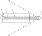
Fig. 1 ~ Fig. 2 is the structural representation that the utility model can load and unload multi-functional rack.
Fig. 3 is the structural representation of connector in the utility model.
Fig. 4 ~ Fig. 5 is the schematic diagram at connector position in the utility model.
The specific embodiment
Further specify architectural feature of the present utility model below in conjunction with drawings and Examples.
Referring to Fig. 1 ~ shown in Figure 2, the utility model can load and unload multi-functional rack, and it comprises: fixed support 1; Connector 2 is fixed on the fixed support 1, and these connector 2 one ends are provided with a connector 21; Grillage 3 plugs and is fixed in the described connector 21, and this grillage 3 offers a draw-in groove 31 along its length; Glove plate 4, one end are embedded in the draw-in groove 31 that is fixed in grillage 3.
Further, referring to shown in Figure 3, offer fixing hole 11 on the described fixed support 1, described connector 2 is by orthogonal two arms be formed by connecting (L type structure or T type structure), the one arm plugs the fixing hole 11 that is fixed in fixed support 1, and another arm top is provided with connector 21.Described fixed support 1 also can directly adopt a pair of retainer ring, and connector 2 corresponding inserted are fixed in the retainer ring.
Referring to Fig. 4 ~ shown in Figure 5, described connector 21 1 end faces are provided with a jack 211, the jack periphery is concaved with the slot 212 of some perforations, be concaved with some holddown grooves that do not connect 213 on connector 21 other ends, convex with the fixed teeth 32 corresponding with described slot 212 and holddown groove 213 on the described grillage 3, fixed teeth 32 is inserted connectors 21 by slot 212 and is fixed in the described holddown groove 213.
Accordingly, described jack 211 periphery correspondences are provided with three pairs of holddown grooves 213, corresponding respectively with glove plate 4 be fixed on horizontal direction, from the horizontal by 30 ° of elevations angle, from the horizontal by 30 ° of angles of depression.
The other end of described glove plate 4 upwards is provided with a stopper section 41.
Described grillage 3 is made up of at least two telescopes nested against one another, the corresponding draw-in groove 31 that is embedded the glove plate that offers on each sleeve pipe.
During installation, because fixed support 1 is vertical annexation with glove plate 4, fixed support 1 should be fixed on the position at close turning on wall or the table, connector 2 one arms are inserted in the fixing hole 11 of fixed support 1, with the grillage 3 corresponding connectors 21 that are fixed on connector 2 another arms that insert, the draw-in groove 31 that glove plate 4 is inserted grillage 3 can be finished the installation of rack again.
During use,, can regulate the angle that glove plate 4 is fixed by the holddown groove 213 of diverse location on the connector 21.For example, glove plate 4 30 degree that are inclined upwardly are fixing, and it is fragile to deposit glasses, paper pen and so on like this, and easily the small articles of fold is difficult for after the placement tumbling; With glove plate 4 horizontal fixed, can be used as bookshelf like this and use, steadily place books; Glove plate 4 downward-sloping 30 degree are fixing, can serve as frame book device, the stopper section of the glove plate other end can stop books or other article landing.
Claims (6)
1. can load and unload multi-functional rack, it is characterized in that, comprise:
Fixed support;
Connector is fixed on the fixed support, and this connector one end is provided with a connector;
Grillage plugs and is fixed in the described connector, and this grillage offers a draw-in groove along its length;
The glove plate, the one end is embedded in the draw-in groove that is fixed in grillage.
2. as claimed in claim 1ly load and unload multi-functional rack, it is characterized in that, offer fixing hole on the described fixed support, described connector is formed by connecting by orthogonal two arms, the one arm plugs and is fixed in support bracket fastened fixing hole, and another arm top is provided with connector.
3. as claimed in claim 1 or 2ly load and unload multi-functional rack, it is characterized in that, the first end face of described connection is provided with a jack, the jack periphery is concaved with the slot of some perforations, be concaved with some holddown grooves that do not connect on the connector other end, convex with on the described grillage and described slot and the corresponding fixed teeth of holddown groove, fixed teeth is inserted connector by slot and is fixed in the described holddown groove.
4. as claimed in claim 3ly load and unload multi-functional rack, it is characterized in that described jack periphery correspondence is provided with three pairs of holddown grooves, corresponding respectively with the glove plate be fixed on horizontal direction, from the horizontal by 30 ° of elevations angle, from the horizontal by 30 ° of angles of depression.
5. describedly load and unload multi-functional rack as claim 1 or 4, it is characterized in that the other end of described glove plate upwards is provided with a stopper section.
6. as claimed in claim 1ly load and unload multi-functional rack, it is characterized in that described grillage is made up of at least two telescopes nested against one another, corresponding having on each sleeve pipe for the draw-in groove that is embedded the glove plate.
Priority Applications (1)
| Application Number | Priority Date | Filing Date | Title |
|---|---|---|---|
| CN2010206246784U CN201879086U (en) | 2010-11-25 | 2010-11-25 | Detachable multi-functional commodity shelf |
Applications Claiming Priority (1)
| Application Number | Priority Date | Filing Date | Title |
|---|---|---|---|
| CN2010206246784U CN201879086U (en) | 2010-11-25 | 2010-11-25 | Detachable multi-functional commodity shelf |
Publications (1)
| Publication Number | Publication Date |
|---|---|
| CN201879086U true CN201879086U (en) | 2011-06-29 |
Family
ID=44176601
Family Applications (1)
| Application Number | Title | Priority Date | Filing Date |
|---|---|---|---|
| CN2010206246784U Expired - Fee Related CN201879086U (en) | 2010-11-25 | 2010-11-25 | Detachable multi-functional commodity shelf |
Country Status (1)
| Country | Link |
|---|---|
| CN (1) | CN201879086U (en) |
Cited By (1)
| Publication number | Priority date | Publication date | Assignee | Title |
|---|---|---|---|---|
| CN112972144A (en) * | 2021-02-26 | 2021-06-18 | 史贵芬 | Take evidence of following nursing bed of health education folded sheet |
-
2010
- 2010-11-25 CN CN2010206246784U patent/CN201879086U/en not_active Expired - Fee Related
Cited By (1)
| Publication number | Priority date | Publication date | Assignee | Title |
|---|---|---|---|---|
| CN112972144A (en) * | 2021-02-26 | 2021-06-18 | 史贵芬 | Take evidence of following nursing bed of health education folded sheet |
Similar Documents
| Publication | Publication Date | Title |
|---|---|---|
| CN203137497U (en) | Folding type on-bed desk | |
| CN201879086U (en) | Detachable multi-functional commodity shelf | |
| CN208708938U (en) | Combined type wardrobe | |
| CN203884967U (en) | Joinable wooden desk of multiple structures | |
| CN203555322U (en) | Foldable table | |
| CN201157143Y (en) | Multifunctional bookshelf | |
| CN210581806U (en) | Folding table ladder for dormitory | |
| CN201452055U (en) | Table mounted on floor | |
| CN210539652U (en) | Foldable simple table | |
| CN203353960U (en) | Portable desk used in bed | |
| CN202489477U (en) | Quitter table with socket | |
| CN201640955U (en) | Multifunctional bedside desk | |
| CN205267429U (en) | Tea table | |
| CN204273743U (en) | A kind of bookshelf being concealed with tables and chairs | |
| CN204444993U (en) | A kind of rotating bedside bookshelf | |
| CN203828336U (en) | Laminated wood table of various structures and capable of being spliced | |
| CN202476893U (en) | Small-sized desk | |
| CN201870115U (en) | Duplex furniture | |
| CN203063778U (en) | Multifunctional bed for motor home | |
| CN219500660U (en) | Financial cabinet | |
| CN203676417U (en) | Multifunctional folding table | |
| CN204015640U (en) | Complete chair | |
| CN203153038U (en) | Desk | |
| CN202161145U (en) | Suspended-type storage table | |
| CN204698093U (en) | A kind of multifunctional table |
Legal Events
| Date | Code | Title | Description |
|---|---|---|---|
| C14 | Grant of patent or utility model | ||
| GR01 | Patent grant | ||
| C17 | Cessation of patent right | ||
| CF01 | Termination of patent right due to non-payment of annual fee |
Granted publication date: 20110629 Termination date: 20111125 |