CN201856445U - Air leakage preventing device of direct plate maker - Google Patents
Air leakage preventing device of direct plate maker Download PDFInfo
- Publication number
- CN201856445U CN201856445U CN2010205369664U CN201020536966U CN201856445U CN 201856445 U CN201856445 U CN 201856445U CN 2010205369664 U CN2010205369664 U CN 2010205369664U CN 201020536966 U CN201020536966 U CN 201020536966U CN 201856445 U CN201856445 U CN 201856445U
- Authority
- CN
- China
- Prior art keywords
- air
- groove
- blocking plug
- gas
- rotary drum
- Prior art date
- Legal status (The legal status is an assumption and is not a legal conclusion. Google has not performed a legal analysis and makes no representation as to the accuracy of the status listed.)
- Expired - Fee Related
Links
- 238000003384 imaging method Methods 0.000 claims abstract description 32
- 238000010521 absorption reaction Methods 0.000 claims description 4
- 230000000977 initiatory effect Effects 0.000 claims description 2
- 238000004519 manufacturing process Methods 0.000 abstract description 2
- 230000000903 blocking effect Effects 0.000 abstract 9
- 230000004888 barrier function Effects 0.000 abstract 1
- 238000010586 diagram Methods 0.000 description 5
- 230000009286 beneficial effect Effects 0.000 description 1
- 230000000694 effects Effects 0.000 description 1
- 230000008030 elimination Effects 0.000 description 1
- 238000003379 elimination reaction Methods 0.000 description 1
- 238000005516 engineering process Methods 0.000 description 1
- 238000009434 installation Methods 0.000 description 1
Images


Landscapes
- Manufacture Or Reproduction Of Printing Formes (AREA)
Abstract
The utility model relates to an air leakage preventing device of a direct plate maker, which comprises a joystick, an air blocking plug and a rotary drum. The device is characterized in that a non-through air groove used for absorbing printing plates is formed on the surface of the rotary drum in the circumferential direction; the length of the air groove is matched with the maximum imaging breadth; a plurality of air extracting holes are formed in the air groove and distributed between the initial end of the air groove and a position capable of being covered by the minimum applicable printing plate; a tongue-shaped part of the air blocking plug is matched with the air groove, and the cross section of the tongue-shaped part of the air blocking plug is totally consistent with the air groove in shape and is slightly smaller than the air groove in size, so that the air blocking plug can move in the air groove without barriers; a concave groove is formed at a flange part of the air blocking plug, and the joystick is placed in the concave groove of the air blocking plug; the joystick can drive the air blocking plug to move in the air groove along the surface of the rotary drum while moving around the axis of the rotary drum along the surface of the rotary drum; and the number of the air blocking plug and the number of the air groove can be respectively one or multiple. The utility model ensures that the printing plates of various breadths can be absorbed on the surface of the rotary drum smoothly and reliably, thereby greatly reducing the requirement for the matching accuracy between the joystick and the air blocking plug and facilitating the manufacturing, the assembly and the replacement.
Description
Technical field
The utility model relates to the direct platemaking machine that a kind of printing industry is used, particularly a kind of anti-gas-leak device of direct platemaking machine.
Background technology
Directly platemaking machine is digitized picture and text output equipment, with the mode of laser scanning imaging with the digitlization picture and text information direct imaging in the computer to the forme that is used to print.On the direct platemaking machine of drum type, forme is fixed on the outer surface of imaging drum, with the rotation of imaging drum one superhigh speed, finishes scanning imagery.Owing to there is very big centrifugal force when rotating at a high speed, make forme might be detached into the picture drum, this can produce serious consequence, therefore forme must be fixed on reliably the surface of imaging drum.
The direct platemaking machine of the drum type of prior art, their forme fixed system substantially all are made up of imaging drum, a version fixture (abbreviation head-clamp), version tail fixture (being called for short the tail folder) and vacuum suction system.
Chinese patent 200920302482.0 discloses a kind of anti-gas-leak device of direct platemaking machine absorption forme.Though the anti-gas-leak device of above-mentioned patent disclosure has solved the problem of gas leakage, there is the problem of assembling and maintain and replace difficulty.
Summary of the invention
The purpose of this utility model is: provide a kind of and install and the very convenient anti-gas-leak device of direct platemaking machine efficiently of maintain and replace.
Above-mentioned technical problem of the present utility model is mainly solved by following technical proposals: a kind of anti-gas-leak device of direct platemaking machine, by control stick, gas shutoff head and imaging drum are formed, it is characterized in that: comprise control stick, gas shutoff head and imaging drum, it is characterized in that: described imaging drum surface along the circumferential direction has the air drain that the absorption forme that do not connect is used, the initiating terminal of described air drain is provided with aspirating hole between the position that minimum suitable forme can cover, described gas shutoff head comprises cross sectional shape ligulate face consistent with air drain and the flange that is positioned at above the ligulate face, described flange place is provided with the groove with imaging drum axis parallel, and described control stick links to each other with the gas shutoff head by groove.
As preferably, the quantity of the utility model control stick, gas shutoff head and air drain is a plurality of.
As preferably, the version tail fixture of the tail end of described control stick and fixing printing block is separated.
As preferably, the version tail fixture of the tail end of described control stick and fixing printing block is integrated, and has simplified system architecture like this.
In existing direct platemaking machine, rotating shaft is two parts of fixedlying connected because tail cramping plate is with the tail folder, there is not relative motion between these two parts, therefore also have tail cramping plate and the rotating shaft of tail folder are united two into one, become the way of a part, in this case, rotate the tail folder and just mean direct rotation tail cramping plate, the rotating shaft of tail folder has been transformed into virtual axle, and at this moment, control stick described in the utility model just can not press from both sides the shared part of rotating shaft with tail.Because tail cramping board size is less, the control stick that a whole piece will be set on it not only can weaken the rigidity and the intensity of tail cramping plate greatly, and the control stick difficulty of such tail cramping plate of processing and manufacturing and whole piece is also very big, therefore, under the situation of a plurality of gas shutoff heads of configuration and air drain on the imaging drum, control stick described in the utility model adopts the structure of minor axis, its quantity is identical with the gas shutoff head, each gas shutoff head is joined a control stick, and the center line of each control stick all is positioned at the place, virtual axle center of tail cramping plate.
The beneficial effects of the utility model are:
1) the anti-gas-leak device can make the smooth surface that is adsorbed in the imaging drum reliably of forme of various breadths;
2) drive part owing to gas shutoff head in the anti-gas-leak device adopts groove structure, has greatly reduced the quality of fit requirement between control stick and the gas shutoff head, is convenient to make, assembles and changes.
Description of drawings
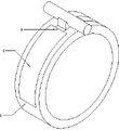
Accompanying drawing 1 is a kind of schematic perspective view of the present utility model;
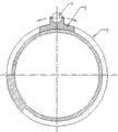
Accompanying drawing 2 is cross section views of Fig. 1;
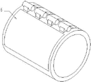
Accompanying drawing 3 is the three-dimensional views after Fig. 1 installs forme;
Accompanying drawing 4 is gas shutoff head moving direction schematic diagrames;
Accompanying drawing 5 is anti-gas-leak device schematic diagrames of a plurality of gas shutoff heads;
Accompanying drawing 6 is scheme of installations of forme under a plurality of gas shutoff head situations.
Accompanying drawing 7 is schematic diagrames of the shared control stick of a plurality of gas shutoff heads.
Shown in the figure: the 1-control stick; 2-gas shutoff head; 3-imaging drum; Air drain on the 4-imaging drum;
The 5-aspirating hole; The 6-forme; A-forme head; B-forme afterbody.
The specific embodiment
Below by embodiment also in conjunction with the accompanying drawings, the technical solution of the utility model is further described in detail.
As shown in Figure 1-Figure 3, imaging drum 3 surfaces along the circumferential direction have the air drain 4 that the absorption forme that do not connect is used, the tongue-shaped member of gas shutoff head 2 cooperates the cross sectional shape of the tongue-shaped member of gas shutoff head 2 and identical with air drain 4, undersized with air drain 4 activities on imaging drum 3 surfaces; The flange portion of gas shutoff head 2 has and the parallel groove of imaging drum axis, and control stick 1 places the groove of gas shutoff head 2; Be installed to the surface of imaging drum 3 when forme 5 after, because the existence of gas shutoff head 2, the air drain 4 on imaging drum 3 surfaces is separated into two mutual disconnected parts, wherein at imaging drum 3, in the zone that gas shutoff head 2 and forme 6 surround, air drain 4 places of imaging drum 3 have formed airtight cavity, by the inboard aspirating hole 5 of imaging drum the air in this closed cavity is taken out, just can in this cavity, form negative pressure,, forme 6 is adsorbed in firmly the surface of imaging drum 3 by means of forme 6 atmosphere outside pressure.
As shown in Figure 4, when the breadth of forme 6 changes, be that forme 6 is when the length of imaging drum 3 circumferential surfaces changes, gas shutoff head 2 can move along the surface of the air drain 4 of imaging drum 3 in the axle center of coiled picture drum under the driving of control stick 1, so just make that the size of the closed cavity that gas shutoff head 2 and forme 6 surround can change along with the change of forme breadth by imaging drum 3.
As mentioned above, utilize gas shutoff head 2 to form airtight cavity, its tongue-shaped member only with the direction of forme 6 tail end B on be only necessary, another side then is dispensable, but from preventing gas shutoff head 2 requirement of self-locking when mobile air drain 4, gas shutoff head 2 both sides all have the design of tongue-shaped member can guarantee that then gas shutoff head 2 has good guiding when mobile in air drain 4, elimination self-locking tendency, guarantee that gas shutoff head 2 unhinderedly moves around in air drain 4, simultaneously, Dui Cheng design also makes part be easy to processing and assembling.
As mentioned above, for reliably at the surface of imaging drum 3 loading and unloading forme 6, the common all outer surfaces of imaging drum 3 of the direct platemaking machine of existing drum type are provided with the head-clamp and the tail folder (not drawing among the figure) of fixing printing block 6 usefulness, head-clamp is arranged on the A end of forme 6, and the tail folder is arranged on the B end of forme 6.Press simplified structure, the requirement of handled easily considers that the manipulation device (not drawing among the figure) of the control stick 1 of gas shutoff head 2 can be combined with the manipulation device of tail folder, makes this device can handle the tail folder, can handle gas shutoff head 2 again.
Fig. 5 and Fig. 6 are the schematic diagram that a plurality of air drains and gas shutoff head cooperate.
Fig. 5 does not install forme, and Fig. 6 is equipped with forme.
Fig. 7 is the schematic diagram of a plurality of gas shutoff heads of joystick manipulation.
Claims (4)
1. the anti-gas-leak device of a direct platemaking machine, comprise control stick (1), gas shutoff head (2) and imaging drum (3), it is characterized in that: described imaging drum (3) surface along the circumferential direction has the air drain (4) that the absorption forme that do not connect is used, the initiating terminal of described air drain (4) is provided with aspirating hole (5) between the position that minimum suitable forme can cover, described gas shutoff head (2) comprises cross sectional shape ligulate face consistent with air drain (4) and the flange that is positioned at above the ligulate face, described flange place is provided with the groove with imaging drum axis parallel, and described control stick (1) links to each other with the gas shutoff head by groove.
2. the anti-gas-leak device of direct platemaking machine according to claim 1, it is characterized in that: the quantity of described control stick (1), gas shutoff head (2) and air drain (4) is a plurality of.
3. the anti-gas-leak device of direct platemaking machine according to claim 1 and 2 is characterized in that: described control stick (1) is integrated with the version tail fixture of the tail end (B) of fixing printing block (6).
4. the anti-gas-leak device of direct platemaking machine according to claim 1 and 2 is characterized in that: described control stick (1) is separated with the version tail fixture of the tail end (B) of fixing printing block (6).
Priority Applications (1)
| Application Number | Priority Date | Filing Date | Title |
|---|---|---|---|
| CN2010205369664U CN201856445U (en) | 2010-09-21 | 2010-09-21 | Air leakage preventing device of direct plate maker |
Applications Claiming Priority (1)
| Application Number | Priority Date | Filing Date | Title |
|---|---|---|---|
| CN2010205369664U CN201856445U (en) | 2010-09-21 | 2010-09-21 | Air leakage preventing device of direct plate maker |
Publications (1)
| Publication Number | Publication Date |
|---|---|
| CN201856445U true CN201856445U (en) | 2011-06-08 |
Family
ID=44102261
Family Applications (1)
| Application Number | Title | Priority Date | Filing Date |
|---|---|---|---|
| CN2010205369664U Expired - Fee Related CN201856445U (en) | 2010-09-21 | 2010-09-21 | Air leakage preventing device of direct plate maker |
Country Status (1)
| Country | Link |
|---|---|
| CN (1) | CN201856445U (en) |
-
2010
- 2010-09-21 CN CN2010205369664U patent/CN201856445U/en not_active Expired - Fee Related
Similar Documents
| Publication | Publication Date | Title |
|---|---|---|
| CN105246804B (en) | Apparatus and process for transferring and rotating objects | |
| CN103507946A (en) | Device for mechanical connection of a control surface to a fixed structural element of an aircraft and aircraft wing element equipped with said device | |
| CN104590592A (en) | Novel spatial electromagnetic docking mechanism | |
| KR102608950B1 (en) | Stopper device for articulated robot | |
| CN107985565A (en) | The unmanned plane undercarriage of taking photo by plane of dual shock absorption | |
| CN105697957A (en) | Support workbench fixing mechanism and unmanned plane | |
| CN113134727A (en) | Box closing gripping apparatus with floating function | |
| CN201856445U (en) | Air leakage preventing device of direct plate maker | |
| CN104743139A (en) | Spatial manipulator structure capable of stably grabbing | |
| US20110180659A1 (en) | Aircraft taxiing actuator | |
| CN108750139A (en) | A wing-fuselage assembly structure and an aircraft having the same | |
| CN201390022Y (en) | Air leakage proof device for printing plate adsorption of imaging drum of CTP (computer to plate) | |
| CN208947637U (en) | Wing fuselage package assembly and have its aircraft | |
| CN203537210U (en) | Non-contact type transmission device with high coaxiality | |
| CN105059540A (en) | Propeller quick-release mechanism | |
| CN106227008A (en) | A kind of novel photoactive drum driving gear and cartridge | |
| CN207843325U (en) | An unmanned aerial vehicle and its opening and closing device for the arm of the unmanned aerial vehicle | |
| CN103501101B (en) | A kind of non-contact type drive mechanism of high-axiality | |
| CN117309141A (en) | A highly integrated filter mechanism based on incomplete gears | |
| CN109194089A (en) | A kind of contactless multi stage magnetic shaft coupling | |
| CN210166538U (en) | Unlocking device of optical transceiver module | |
| CN222732066U (en) | Reinforced differential mechanism shell | |
| CN206826928U (en) | For unmanned plane propeller installing plate and the connector of fuselage | |
| CN206717286U (en) | A kind of twin-roll jaw means | |
| CN218431709U (en) | Quick beta structure of using on unmanned aerial vehicle |
Legal Events
| Date | Code | Title | Description |
|---|---|---|---|
| C14 | Grant of patent or utility model | ||
| GR01 | Patent grant | ||
| C17 | Cessation of patent right | ||
| CF01 | Termination of patent right due to non-payment of annual fee |
Granted publication date: 20110608 Termination date: 20120921 |