CN201848900U - Hole forming device - Google Patents
Hole forming device Download PDFInfo
- Publication number
- CN201848900U CN201848900U CN2010205339442U CN201020533944U CN201848900U CN 201848900 U CN201848900 U CN 201848900U CN 2010205339442 U CN2010205339442 U CN 2010205339442U CN 201020533944 U CN201020533944 U CN 201020533944U CN 201848900 U CN201848900 U CN 201848900U
- Authority
- CN
- China
- Prior art keywords
- calandria
- parts
- cutting device
- nested
- cutter sweep
- Prior art date
- Legal status (The legal status is an assumption and is not a legal conclusion. Google has not performed a legal analysis and makes no representation as to the accuracy of the status listed.)
- Expired - Fee Related
Links
- 238000010438 heat treatment Methods 0.000 claims abstract description 25
- 238000009413 insulation Methods 0.000 claims abstract description 13
- 239000000463 material Substances 0.000 claims abstract description 9
- 230000003750 conditioning effect Effects 0.000 claims description 11
- 241000826860 Trapezium Species 0.000 claims description 3
- 238000000465 moulding Methods 0.000 claims description 3
- 230000000694 effects Effects 0.000 claims description 2
- 230000005611 electricity Effects 0.000 claims description 2
- 239000000843 powder Substances 0.000 abstract description 3
- 238000002347 injection Methods 0.000 abstract 1
- 239000007924 injection Substances 0.000 abstract 1
- 239000011810 insulating material Substances 0.000 abstract 1
- 238000000034 method Methods 0.000 description 5
- 229920003023 plastic Polymers 0.000 description 4
- 239000004033 plastic Substances 0.000 description 4
- 238000005553 drilling Methods 0.000 description 3
- 238000010586 diagram Methods 0.000 description 2
- 238000005516 engineering process Methods 0.000 description 2
- 230000008929 regeneration Effects 0.000 description 2
- 238000011069 regeneration method Methods 0.000 description 2
- 238000011109 contamination Methods 0.000 description 1
- 230000001276 controlling effect Effects 0.000 description 1
- 230000007812 deficiency Effects 0.000 description 1
- 239000000284 extract Substances 0.000 description 1
- 235000013312 flour Nutrition 0.000 description 1
- 230000035515 penetration Effects 0.000 description 1
- 238000007639 printing Methods 0.000 description 1
- 230000001105 regulatory effect Effects 0.000 description 1
- 230000008439 repair process Effects 0.000 description 1
Images


Classifications
-
- Y—GENERAL TAGGING OF NEW TECHNOLOGICAL DEVELOPMENTS; GENERAL TAGGING OF CROSS-SECTIONAL TECHNOLOGIES SPANNING OVER SEVERAL SECTIONS OF THE IPC; TECHNICAL SUBJECTS COVERED BY FORMER USPC CROSS-REFERENCE ART COLLECTIONS [XRACs] AND DIGESTS
- Y02—TECHNOLOGIES OR APPLICATIONS FOR MITIGATION OR ADAPTATION AGAINST CLIMATE CHANGE
- Y02W—CLIMATE CHANGE MITIGATION TECHNOLOGIES RELATED TO WASTEWATER TREATMENT OR WASTE MANAGEMENT
- Y02W30/00—Technologies for solid waste management
- Y02W30/50—Reuse, recycling or recovery technologies
- Y02W30/62—Plastics recycling; Rubber recycling
Landscapes
- Perforating, Stamping-Out Or Severing By Means Other Than Cutting (AREA)
Abstract
一种开孔装置,该装置包括加热体和切割器件装置两部分,该两部分可以拧合在一起,所述加热体内部装有温控单元,温控单元可以根据操作需要对注塑件的材质进行温度调节,加热体底部有一嵌套链接口,由内外两部分组成,两部分可以在外力的作用下相互滑动,用来控制本开孔装置的开关,所述的切割装置外部为隔热材料做成的隔热筒,下部装有切割器件。该发明装置因为加热体包括温控单元,可以适用于不同材质的硒鼓粉仓,使用起来更加安全、灵活、方便。
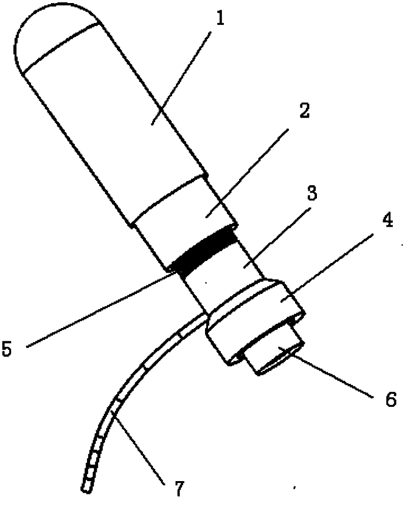
A hole opening device, the device includes two parts of a heating body and a cutting device device, the two parts can be twisted together, the heating body is equipped with a temperature control unit, the temperature control unit can adjust the material of the injection molded part according to the operation needs For temperature adjustment, there is a nested chain interface at the bottom of the heating body, which is composed of two parts inside and outside, and the two parts can slide each other under the action of external force to control the switch of the opening device. The outside of the cutting device is made of heat insulating material The heat insulation tube made, the lower part is equipped with a cutting device. Because the heating body includes a temperature control unit, the inventive device can be applied to toner cartridge powder bins of different materials, and is safer, more flexible and more convenient to use.
Description
Claims (5)
Priority Applications (1)
| Application Number | Priority Date | Filing Date | Title |
|---|---|---|---|
| CN2010205339442U CN201848900U (en) | 2010-09-17 | 2010-09-17 | Hole forming device |
Applications Claiming Priority (1)
| Application Number | Priority Date | Filing Date | Title |
|---|---|---|---|
| CN2010205339442U CN201848900U (en) | 2010-09-17 | 2010-09-17 | Hole forming device |
Publications (1)
| Publication Number | Publication Date |
|---|---|
| CN201848900U true CN201848900U (en) | 2011-06-01 |
Family
ID=44091311
Family Applications (1)
| Application Number | Title | Priority Date | Filing Date |
|---|---|---|---|
| CN2010205339442U Expired - Fee Related CN201848900U (en) | 2010-09-17 | 2010-09-17 | Hole forming device |
Country Status (1)
| Country | Link |
|---|---|
| CN (1) | CN201848900U (en) |
Cited By (1)
| Publication number | Priority date | Publication date | Assignee | Title |
|---|---|---|---|---|
| CN102079101A (en) * | 2010-09-17 | 2011-06-01 | 富美科技有限公司 | Punching device |
-
2010
- 2010-09-17 CN CN2010205339442U patent/CN201848900U/en not_active Expired - Fee Related
Cited By (1)
| Publication number | Priority date | Publication date | Assignee | Title |
|---|---|---|---|---|
| CN102079101A (en) * | 2010-09-17 | 2011-06-01 | 富美科技有限公司 | Punching device |
Similar Documents
| Publication | Publication Date | Title |
|---|---|---|
| CN102079101A (en) | Punching device | |
| CN104275801B (en) | A kind of 3D prints plastic material welder | |
| CN207808506U (en) | A 3D printing consumable molding device | |
| CN201848900U (en) | Hole forming device | |
| CN103640222A (en) | Three-dimensional (3D) printing equipment | |
| CN203426440U (en) | Quantitative powder feeding device | |
| CN211307165U (en) | An automatic injection molding unit that is easy to move | |
| CN202155625U (en) | Electric soldering iron for welding wax pattern assemblies | |
| CN205030661U (en) | Self -heating cutlery box | |
| CN203061149U (en) | Multi-parameter controlled single particle granulating test bed | |
| KR101407496B1 (en) | Apparatus for producing refuse derived fuel | |
| CN206999624U (en) | A kind of efficient 3D printing pen | |
| CN205466556U (en) | Device is tailor in wrapping bag | |
| CN202893312U (en) | Rapid melting device | |
| CN203074371U (en) | Automatic frying pan | |
| CN101644910A (en) | Toner cartridge bin opening device | |
| KR101597938B1 (en) | Apparatus for producing refuse derived fuel | |
| CN202374958U (en) | Dough Quantitative Divider | |
| CN204054485U (en) | A kind of injection machine hopper with warning device | |
| CN202572501U (en) | Electric heating cutter | |
| CN102632519A (en) | Opener | |
| CN203228524U (en) | Binding machine with high temperature prompting function and hot riveting head thereof | |
| CN203125120U (en) | Automated assembly machine for insulating piece | |
| KR20160071656A (en) | Three-dimensional material supply device of the printer | |
| CN206633436U (en) | A kind of rotating disc type high-frequency fusing machine for preventing burn failure |
Legal Events
| Date | Code | Title | Description |
|---|---|---|---|
| C14 | Grant of patent or utility model | ||
| GR01 | Patent grant | ||
| C56 | Change in the name or address of the patentee |
Owner name: FOREVER TECHNOLOGY GROUP CO., LTD. Free format text: FORMER NAME: FOREVER SCIENCE AND TECHNOLOGY CO., LTD. |
|
| CP03 | Change of name, title or address |
Address after: 250306 Shandong city of Ji'nan province Ji'nan Economic Development Zone (Changqing Peace Road) forrich Formica Technology Group Limited Patentee after: Fumei Technology Group Co.,Ltd. Address before: 250306 Fu Jing Road, Ji'nan Economic Development Zone, Ji'nan, Shandong, Changqing Patentee before: Forever Science and Technology Co., Ltd. |
|
| PE01 | Entry into force of the registration of the contract for pledge of patent right | ||
| PE01 | Entry into force of the registration of the contract for pledge of patent right |
Denomination of utility model: Punching device Effective date of registration: 20140123 Granted publication date: 20110601 Pledgee: China Shipping XinDa, Company limited by guarantee Pledgor: Fumei Technology Group Co.,Ltd. Registration number: 2014990000043 |
|
| PC01 | Cancellation of the registration of the contract for pledge of patent right |
Date of cancellation: 20140702 Granted publication date: 20110601 Pledgee: China Shipping XinDa, Company limited by guarantee Pledgor: Fumei Technology Group Co.,Ltd. Registration number: 2014990000043 |
|
| PLDC | Enforcement, change and cancellation of contracts on pledge of patent right or utility model | ||
| PP01 | Preservation of patent right |
Effective date of registration: 20151124 Granted publication date: 20110601 |
|
| RINS | Preservation of patent right or utility model and its discharge | ||
| PD01 | Discharge of preservation of patent |
Date of cancellation: 20160524 Granted publication date: 20110601 |
|
| PP01 | Preservation of patent right |
Effective date of registration: 20160524 Granted publication date: 20110601 |
|
| RINS | Preservation of patent right or utility model and its discharge | ||
| PD01 | Discharge of preservation of patent | ||
| PD01 | Discharge of preservation of patent |
Date of cancellation: 20200917 Granted publication date: 20110601 |
|
| DD01 | Delivery of document by public notice | ||
| DD01 | Delivery of document by public notice |
Addressee: Liu Lili Document name: Notice of termination of proceedings Addressee: Wang Zhigang Document name: Notice of termination of proceedings |
|
| DD01 | Delivery of document by public notice | ||
| DD01 | Delivery of document by public notice |
Addressee: Liu Lili Document name: Notice of termination of patent |
|
| CF01 | Termination of patent right due to non-payment of annual fee | ||
| CF01 | Termination of patent right due to non-payment of annual fee |
Granted publication date: 20110601 Termination date: 20150917 |