CN201848765U - Electromagnetic centerless fixture - Google Patents
Electromagnetic centerless fixture Download PDFInfo
- Publication number
- CN201848765U CN201848765U CN2010206000106U CN201020600010U CN201848765U CN 201848765 U CN201848765 U CN 201848765U CN 2010206000106 U CN2010206000106 U CN 2010206000106U CN 201020600010 U CN201020600010 U CN 201020600010U CN 201848765 U CN201848765 U CN 201848765U
- Authority
- CN
- China
- Prior art keywords
- magnetic
- core
- magnetic core
- workpiece
- magnetic pole
- Prior art date
- Legal status (The legal status is an assumption and is not a legal conclusion. Google has not performed a legal analysis and makes no representation as to the accuracy of the status listed.)
- Expired - Fee Related
Links
Images
Landscapes
- Jigs For Machine Tools (AREA)
Abstract
The utility model discloses an electromagnetic centerless fixture which comprises a hollow magnetic core, a fixture body sheathed outside the magnetic core, and a cover plate fixedly connected on the fixture body, and is characterized in that the fixture body is internally provided with a coil; the magnetic core is fixedly connected with a magnetic pole arranged at the outer end of the magnetic core into a whole; the fixture body, the magnetic core and the magnetic pole are magnetic conductors; the fixture body is also fixedly connected with a terminal pad which is connected with two supporting seats by a bolt and a nut; each supporting seat is connected with a supporting block; the two supporting blocks form an included angle and are positioned under the magnetic pole; and the heads of the two supporting blocks are magnetic isolating bodies. The electromagnetic centerless fixture has the advantages of being rapid in clamping a workpiece, high in efficiency and small in deformation of the workpiece, and is comparatively simple in structure, firm in location of the workpiece and convenient to adjust and replace.
Description
Technical field
The utility model relates to a kind of electric magnetic no-core clamp that is used for grinding machine.
Background technology
At present, grinding machine generally adopts mechanical three-pawl type self-centering manual to come workpiece is carried out clamping, shortcomings such as clamping workpiece is slow, efficient is low, workpiece deformation is big, the difficult control of clamping force that it exists; The electromagnetic type anchor clamps had appearred afterwards, but it exist structure comparatively complicated, insecure to the location of workpiece, adjust and change shortcoming such as inconvenience.
The utility model content
The purpose of this utility model is the above-mentioned deficiency at prior art, a kind of electric magnetic no-core clamp is provided, it had both had the advantage that clamping workpiece is fast, efficient is high, workpiece deformation is little, simultaneously structure simple relatively, to the firm position of workpiece, and be convenient to adjust and change.
For achieving the above object, electric magnetic no-core clamp of the present utility model, comprise hollow magnetic core, be placed in the outer clamp body of magnetic core, be fixed on the cover plate on the clamp body, it is characterized in that in clamp body, being provided with coil, the magnetic pole of magnetic core and its outer end is fixedly connected, and clamp body, magnetic core, magnetic pole are magnetic conductor; Also be fixedly connected with terminal pad on clamp body, terminal pad links to each other with two supporting bases by bolts and nuts, and each supporting base all connects a rest pad, and two rest pads are an angle setting and are positioned at the magnetic pole below, and the head of two rest pads is every magnet.
During use, magnetic core is connected with machine tool chief axis, and clamp body connects coil electricity with the lathe end cap, clamp body, magnetic core, magnetic pole all are with magnetic, workpiece is by slightly eccentric being adsorbed on the magnetic pole end face, and two rest pads contact with workpiece simultaneously, and it is provided support, the utility model structure is simple relatively, to the firm position of workpiece, whole process clamping workpiece is fast, efficient is high, and workpiece is not subjected to chucking power, is out of shape little;
As further improvement of the utility model, between magnetic core and magnetic pole, also be provided with disk into magnetic conductor, magnetic core, disk, magnetic pole connect by bolt successively; Be convenient to change the magnetic pole of different model;
As further improvement of the utility model, on disk, also be installed with every disk, be NULL every disk; Can avoid producing leakage field, prevent from the installation of workpiece is exerted an influence in this zone;
As further improvement of the utility model, each supporting base is equipped with chute with corresponding rest pad, and the chute direction of the two is intersected, and supporting base and corresponding rest pad are by placing the bolt and lock nut connection of the two chute; By adjusting the position of bolt in two chutes, can adjust the position of rest pad, enlarge the scope of application of these anchor clamps;
As further improvement of the utility model, in terminal pad, be provided with arc chute, connect terminal pad and place in this arc chute with the head of the bolt of corresponding supporting base; By adjusting the position of this bolt in arc chute, can adjust the angle of two rest pads, enlarge the scope of application of these anchor clamps;
In sum, the utility model had both had the advantage that clamping workpiece is fast, efficient is high, workpiece deformation is little, simultaneously structure simple relatively, to the firm position of workpiece, and be convenient to adjust and change.
Description of drawings
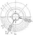
Fig. 1 is the front view of the utility model embodiment.
Fig. 2 is the right view of Fig. 1.
The specific embodiment
Below in conjunction with accompanying drawing the utility model is described in further detail.
As shown in Figure 1 and Figure 2, this electric magnetic no-core clamp, comprise hollow magnetic core 1, be placed in the outer clamp body 2 of magnetic core 1, be fixed on the cover plate 3 on the clamp body 2, be provided with coil 4 in clamp body 2, the disk of magnetic core 1 and its outer end 5 is connected by bolt, and the magnetic pole of disk 5 and its outer end 6 is connected by bolt, clamp body 2, magnetic core 1, disk 5, magnetic pole 6 are magnetic conductor, also being installed with every disk 7 by screw on disk 5, is NULL every disk 7, as aluminium; Also be fixedly connected with semicircular terminal pad 8 by bolt on clamp body 2, be provided with arc chute 8a in terminal pad 8, terminal pad 8 links to each other with two supporting bases 10 with nut by two bolts 9, and the head of this bolt 9 places in the arc chute 8a; Each supporting base 10 all connects a rest pad 11, and each supporting base 10 is equipped with chute with corresponding rest pad 11, and the chute direction of the two is intersected, and supporting base 10 is connected with locking nut by the bolt 12 that places the two chute with corresponding rest pad 11; Two rest pads 11 are an angle setting and are positioned at magnetic pole 6 belows, and the head 11a of two rest pads 11 is every magnet, as carbide alloy.
During use, magnetic core 1 is connected with machine tool chief axis, clamp body 2 connects with the lathe end cap, coil 4 energisings, clamp body 2, magnetic core 1, disk 5, magnetic pole 6 all are with magnetic, and workpiece 13 is by slightly eccentric being adsorbed on magnetic pole 6 end faces, two rest pads 11 contact with workpiece 13 simultaneously, and it is provided support; Can avoid producing leakage field every disk 7, prevent from the installation of workpiece 13 is exerted an influence in this zone; By adjusting position and bolt 9 the position among arc chute 8as of bolt 12 in two chutes, can adjust the position of rest pad 11 and the angle of two rest pads 11, enlarge the scope of application of these anchor clamps; The utility model had both had the advantage that clamping workpiece is fast, efficient is high, workpiece deformation is little, simultaneously structure simple relatively, to the firm position of workpiece, and be convenient to adjust and change.
Claims (5)
1. electric magnetic no-core clamp, comprise hollow magnetic core, be placed in the outer clamp body of magnetic core, be fixed on the cover plate on the clamp body, it is characterized in that being provided with in clamp body coil, the magnetic pole of magnetic core and its outer end is fixedly connected, and clamp body, magnetic core, magnetic pole are magnetic conductor; Also be fixedly connected with terminal pad on clamp body, terminal pad links to each other with two supporting bases by bolts and nuts, and each supporting base all connects a rest pad, and two rest pads are an angle setting and are positioned at the magnetic pole below, and the head of two rest pads is every magnet.
2. electric magnetic no-core clamp as claimed in claim 1 is characterized in that also being provided with the disk into magnetic conductor between magnetic core and magnetic pole, magnetic core, disk, magnetic pole connect by bolt successively.
3. electric magnetic no-core clamp as claimed in claim 2 is characterized in that also being installed with every disk on disk.
4. as the arbitrary described electric magnetic no-core clamp of claim 1 to 3, it is characterized in that each supporting base is equipped with chute with corresponding rest pad, the two chute direction is intersected, and supporting base and corresponding rest pad are by placing the bolt and lock nut connection of the two chute.
5. electric magnetic no-core clamp as claimed in claim 4 is characterized in that being provided with arc chute in terminal pad, connect terminal pad and place in this arc chute with the head of the bolt of corresponding supporting base.
Priority Applications (1)
| Application Number | Priority Date | Filing Date | Title |
|---|---|---|---|
| CN2010206000106U CN201848765U (en) | 2010-11-10 | 2010-11-10 | Electromagnetic centerless fixture |
Applications Claiming Priority (1)
| Application Number | Priority Date | Filing Date | Title |
|---|---|---|---|
| CN2010206000106U CN201848765U (en) | 2010-11-10 | 2010-11-10 | Electromagnetic centerless fixture |
Publications (1)
| Publication Number | Publication Date |
|---|---|
| CN201848765U true CN201848765U (en) | 2011-06-01 |
Family
ID=44091176
Family Applications (1)
| Application Number | Title | Priority Date | Filing Date |
|---|---|---|---|
| CN2010206000106U Expired - Fee Related CN201848765U (en) | 2010-11-10 | 2010-11-10 | Electromagnetic centerless fixture |
Country Status (1)
| Country | Link |
|---|---|
| CN (1) | CN201848765U (en) |
Cited By (6)
| Publication number | Priority date | Publication date | Assignee | Title |
|---|---|---|---|---|
| CN103213065A (en) * | 2013-04-24 | 2013-07-24 | 重庆山青机械制造有限公司 | Grinding jig for clamping five-range shifting fork |
| CN103978408A (en) * | 2014-04-30 | 2014-08-13 | 洛阳理工学院 | Off-machine pre-adjusted circular arc-shaped centreless supporter for bearing grinders |
| CN104227561A (en) * | 2014-08-19 | 2014-12-24 | 洛阳维斯格轴承有限公司 | Clamp device for grinding outer circle of gear-shaped bearing |
| CN104325401A (en) * | 2014-11-27 | 2015-02-04 | 无锡市明鑫数控磨床有限公司 | Electromagnetic centerless clamp used by vertical type grinding machine |
| CN108818307A (en) * | 2018-09-12 | 2018-11-16 | 哈尔滨理工大学 | A kind of automatic clamp for machining design of revolving parts |
| CN113523944A (en) * | 2021-07-27 | 2021-10-22 | 八环科技集团股份有限公司 | Grinding process for full-complement bearing rolling element filling port |
-
2010
- 2010-11-10 CN CN2010206000106U patent/CN201848765U/en not_active Expired - Fee Related
Cited By (6)
| Publication number | Priority date | Publication date | Assignee | Title |
|---|---|---|---|---|
| CN103213065A (en) * | 2013-04-24 | 2013-07-24 | 重庆山青机械制造有限公司 | Grinding jig for clamping five-range shifting fork |
| CN103978408A (en) * | 2014-04-30 | 2014-08-13 | 洛阳理工学院 | Off-machine pre-adjusted circular arc-shaped centreless supporter for bearing grinders |
| CN104227561A (en) * | 2014-08-19 | 2014-12-24 | 洛阳维斯格轴承有限公司 | Clamp device for grinding outer circle of gear-shaped bearing |
| CN104325401A (en) * | 2014-11-27 | 2015-02-04 | 无锡市明鑫数控磨床有限公司 | Electromagnetic centerless clamp used by vertical type grinding machine |
| CN108818307A (en) * | 2018-09-12 | 2018-11-16 | 哈尔滨理工大学 | A kind of automatic clamp for machining design of revolving parts |
| CN113523944A (en) * | 2021-07-27 | 2021-10-22 | 八环科技集团股份有限公司 | Grinding process for full-complement bearing rolling element filling port |
Similar Documents
| Publication | Publication Date | Title |
|---|---|---|
| CN201848765U (en) | Electromagnetic centerless fixture | |
| CN203197642U (en) | Rapid centering device for ring-shaped parts | |
| CN112824020A (en) | Fixture capable of centering and clamping hard alloy bars with different diameters | |
| CN208214878U (en) | A kind of new CNC side plate clamping tooling | |
| CN202219411U (en) | Balance chuck clamp | |
| CN106346322B (en) | The fixture of bearing grinder | |
| CN216097737U (en) | Electric permanent magnetic chuck convenient to adjust | |
| CN116330010A (en) | Large-scale fixture for milling machine | |
| CN206316862U (en) | A kind of fixture of bearing grinder | |
| CN107538258A (en) | Magnetic holding device | |
| CN110434737A (en) | A kind of Ru-Fe-Mn's rotor magnet grinding equipment | |
| CN102328215A (en) | End cover connecting flange surface milling tooling for integral speed reducer casing | |
| CN212122960U (en) | Clamping device for stator and rotor detection | |
| CN201792239U (en) | Round electrical permanent magnetic chuck for vertical lathe | |
| CN101733659A (en) | Machining fixture of arc-shaped plate | |
| CN203409650U (en) | Grinding machine | |
| CN202571357U (en) | Pneumatic fixture arranged on lathe | |
| CN201848749U (en) | Adjustable clamp for grinding separation surfaces of automobile connecting rod body | |
| CN202356915U (en) | Quick-change clamp device | |
| CN206293644U (en) | Multifunctional efficient earthing or grounding means | |
| CN210927383U (en) | Motor iron core tire for high-power pump | |
| CN212443613U (en) | A frock clamp for neodymium iron boron magnetism body wire cut electrical discharge machining | |
| CN210388471U (en) | A flip structure for aluminum alloy processing | |
| CN101934481A (en) | Circular electro-permanent magnetic chuck for vertical lathe | |
| CN201625882U (en) | Magnetic pole-variable large-sized core-free clamping device |
Legal Events
| Date | Code | Title | Description |
|---|---|---|---|
| C14 | Grant of patent or utility model | ||
| GR01 | Patent grant | ||
| CF01 | Termination of patent right due to non-payment of annual fee |
Granted publication date: 20110601 Termination date: 20161110 |
|
| CF01 | Termination of patent right due to non-payment of annual fee |