CN201848596U - Compound saw with saw blade protective device and saw blade protective device thereof - Google Patents
Compound saw with saw blade protective device and saw blade protective device thereof Download PDFInfo
- Publication number
- CN201848596U CN201848596U CN2010205891137U CN201020589113U CN201848596U CN 201848596 U CN201848596 U CN 201848596U CN 2010205891137 U CN2010205891137 U CN 2010205891137U CN 201020589113 U CN201020589113 U CN 201020589113U CN 201848596 U CN201848596 U CN 201848596U
- Authority
- CN
- China
- Prior art keywords
- turning cylinder
- saw blade
- saw
- frame
- protective cover
- Prior art date
- Legal status (The legal status is an assumption and is not a legal conclusion. Google has not performed a legal analysis and makes no representation as to the accuracy of the status listed.)
- Expired - Fee Related
Links
- 230000001681 protective effect Effects 0.000 title claims abstract description 61
- 150000001875 compounds Chemical class 0.000 title claims abstract description 31
- 238000010586 diagram Methods 0.000 description 3
- 230000000694 effects Effects 0.000 description 3
- 238000005516 engineering process Methods 0.000 description 2
- 238000000034 method Methods 0.000 description 1
Images


Landscapes
- Sawing (AREA)
Abstract
The utility model discloses a compound saw with a saw blade protective device, which comprises a machine head, a rotary support and a frame, wherein the machine head is provided with a saw blade; the machine head is connected with the frame through the rotary support; the machine head is provided with the saw blade protective device; the saw blade protective device comprises a protective cover, a rotating shaft and a rack, and the rack is fixedly arranged at the machine head of the compound saw; the protective cover is connected with the rack through the rotating shaft, and the protective cover is fixedly connected with the rotating shaft; a limiting hole is formed on one side surface of the rotary support; and the rotating shaft penetrates through the rack, one end of the rotating haft can be matched with the limiting hole of the rotary support, and a positioning groove is formed at the other end of the rotating shaft. The protective cover and a table cutting and oblique cutting switching mechanism are combined together, the protection is implemented during table cutting, the protective cover can be automatically returned into the rack under the action of a spring when being switched to oblique cutting, thereby avoiding the intervention between the protective cover and a workpiece and simultaneously eliminating the inconvenience caused by disassembly and assembly of a protective frame. The utility model further discloses the saw blade protective device of the compound saw.
Description
Technical field
The utility model relates to a kind of compound saw, is specifically related to a kind of compound saw of band saw blade protective device.The utility model also relates to a kind of saw blade protective device of compound saw.
Background technology
According to the regulation of existing safety standard, electric miter saw and bench saw be not when working, and its saw blade cutting edge can not expose and touch.Compound saw with mitre saw and bench saw function has two kinds of duties: the platform cut is made state and the duty of cutting sth. askew.Do under the state at the platform cut, the table top below is exposed the saw blade protection of protection, the especially latter half of saw blade part saw blade, general at present employing is fixed on the mode that fender bracket is installed on the frame or in addition with protective cover and is protected.
The saw blade protected mode of existing compound saw is being converted to when cutting sth. askew duty, and the protective cover that is fixed on the frame can interfere with workpiece, hinders the saw blade horizontal movement; And the mode that fender bracket is installed in addition is being converted to when cutting sth. askew duty, and the operation of can cutting sth. askew after must being removed by artificial fender bracket cause the inconvenience of use.
The utility model content
Technical problem to be solved in the utility model provides a kind of compound saw of band saw blade protective device, and it can implement protection to the saw blade that expose later the table top below under the platform cut is made state.
For solving the problems of the technologies described above, the technical solution of the compound saw of the utility model band saw blade protective device is:
Comprise head, runing rest, support, head is provided with saw blade; Head connects support by runing rest; Described head is provided with the saw blade protective device; Described saw blade protective device comprises protective cover, turning cylinder, frame, and frame is fixedly set in the head of described compound saw; Protective cover connects frame by turning cylinder, and protective cover is fixedlyed connected with turning cylinder; A side of runing rest is provided with spacing hole; Turning cylinder runs through frame, and an end of turning cylinder can match with the spacing hole of runing rest, and the other end of turning cylinder is provided with locating slot; One end of turning cylinder also is provided with lock handle; By drawing rotation turning cylinder, can make turning cylinder rotate translation with respect to frame; Turning cylinder is provided with torsion spring.
Make state when compound saw is in the platform cut, an end of turning cylinder stretches in the spacing hole of runing rest, and the realization platform is cut locking; When compound saw is in the duty of cutting sth. askew, an end of turning cylinder shifts out spacing hole, realizes that platform cuts the location release.
The utility model also provides a kind of saw blade protective device of compound saw, and its technical solution is:
Comprise protective cover, turning cylinder, frame, protective cover connects frame by turning cylinder, and protective cover is fixedlyed connected with turning cylinder; Turning cylinder runs through frame, and an end of turning cylinder can match with the spacing hole that is arranged at runing rest, and the other end of turning cylinder is provided with locating slot; One end of turning cylinder is provided with lock handle.Turning cylinder is provided with torsion spring.
The technique effect that the utility model can reach is:
The utility model is cut the switching mechanism of cutting sth. askew with protective cover and platform and is lumped together; implement protection during cutting on table, be converted to when cutting sth. askew, this protective cover can be under the effect of spring in the self-return frame; avoid protective cover and workpiece to interfere, can save the inconvenience that the dismounting fender bracket brings simultaneously.
Description of drawings
Below in conjunction with the drawings and specific embodiments the utility model is described in further detail:
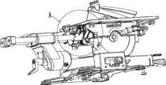
Fig. 1 is the structural representation of the compound saw of the utility model band saw blade protective device;
Fig. 2 is the partial enlarged drawing of A among Fig. 1;
Fig. 3 is that the utility model is in the schematic diagram that the platform cut is made state;
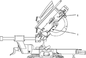
Fig. 4 is the schematic diagram that the utility model is in the duty of cutting sth. askew;
Fig. 5 is the schematic diagram that duty shown in Figure 4 is removed frame;
Fig. 6 is the stereogram that the utility model is in another angle of the duty of cutting sth. askew;
Fig. 7 is the partial enlarged drawing of B among Fig. 6.
Description of reference numerals among the figure:
1 is protective cover, and 2 is turning cylinder,
3 is torsion spring, and 4 is lock handle,
5 is frame, and 6 is spacing hole,
7 is locating slot, and 8 is runing rest.
The specific embodiment
As shown in Figure 1 and Figure 2, the compound saw of the utility model band saw blade protective device comprises head, runing rest 8, support, and head is provided with saw blade; Head connects supports by runing rest 8, the platform that runing rest 8 is used to the to change compound saw duty of cutting, cut sth. askew; Head is provided with the saw blade protective device;
The saw blade protective device comprises protective cover 1, turning cylinder 2, torsion spring 3, frame 5, and frame 5 is fixedly set in the head of compound saw;
A side of runing rest 8 is provided with spacing hole 6;
Turning cylinder 2 runs through frame 5, and an end of turning cylinder 2 stretches out from the spacing hole 6 on the runing rest 8, and the other end of turning cylinder 2 is provided with locating slot 7, and this end of turning cylinder 2 also is provided with lock handle 4; By drawing rotation turning cylinder 2, can make turning cylinder 2 with respect to frame 5 rotations, and translation vertically;
Turning cylinder 2 is provided with torsion spring 3.
When compound saw need enter the platform cut and makes state, drawing twist-lock handle 4, make turning cylinder 2 drive protective cover 1 rotation, press down frame 5 simultaneously, make an end of turning cylinder 2 go into to be positioned at spacing hole 6 on the runing rest 8, frame is locked with the translation function that realization is cut sth. askew and platform is cut, realize protection, as shown in Figure 2 the saw blade rear portion; One end of turning cylinder 2 is limited in the spacing hole 6 on the runing rest 8, realizes that platform cuts locking, as shown in Figure 3;
When compound saw need enter when cutting sth. askew duty, drawing twist-lock handle 4 is removed an end of turning cylinder 2 from spacing hole 6; Rotate turning cylinder 2 simultaneously; make the other end of turning cylinder 2 be positioned in locating slot 7; the realization platform is cut the location release; turning cylinder 2 drives protective cover 1 reverse rotation simultaneously; make protective cover 1 withdraw from protection saw blade state; protective cover 1 rotates in the frame 5 under the effect of torsion spring 3, reaches the state of cutting sth. askew, and is extremely shown in Figure 7 as Fig. 4.
The saw blade protective device of the compound saw of the utility model comprises protective cover 1, turning cylinder 2, torsion spring 3, frame 5, and frame 5 is fixedly set in the head of compound saw;
Turning cylinder 2 runs through frame 5, and an end of turning cylinder 2 can match with the spacing hole 6 of runing rest 8, and the other end of turning cylinder 2 is provided with locating slot 7, and this end of turning cylinder 2 is provided with lock handle 4;
Turning cylinder 2 is provided with torsion spring 3.
Claims (4)
1. the compound saw of a band saw blade protective device comprises head, runing rest, support, and head is provided with saw blade; Head connects support by runing rest; It is characterized in that: described head is provided with the saw blade protective device;
Described saw blade protective device comprises protective cover (1), turning cylinder (2), frame (5), and frame (5) is fixedly set in the head of described compound saw; Protective cover (1) connects frame (5) by turning cylinder (2), and protective cover (1) is fixedlyed connected with turning cylinder (2);
A side of runing rest (8) is provided with spacing hole (6); Turning cylinder (2) runs through frame (5), and an end of turning cylinder (2) can match with the spacing hole (6) of runing rest (8), and the other end of turning cylinder (2) is provided with locating slot (7); One end of turning cylinder (2) also is provided with lock handle (4); By drawing rotation turning cylinder (2), can make turning cylinder (2) with respect to frame (5) rotation translation;
Make state when compound saw is in the platform cut, an end of turning cylinder (2) stretches in the spacing hole (6) of runing rest (8), and the realization platform is cut locking;
When compound saw is in the duty of cutting sth. askew, an end of turning cylinder (2) shifts out spacing hole (6), realizes that platform cuts the location release.
2. the compound saw of band saw blade protective device according to claim 1 is characterized in that: described turning cylinder (2) is provided with torsion spring (3).
3. the saw blade protective device of a compound saw is characterized in that: comprise protective cover (1), turning cylinder (2), frame (5), protective cover (1) connects frame (5) by turning cylinder (2), and protective cover (1) is fixedlyed connected with turning cylinder (2); Turning cylinder (2) runs through frame (5), and an end of turning cylinder (2) can match with the spacing hole that is arranged at runing rest (8) (6), and the other end of turning cylinder (2) is provided with locating slot (7); One end of turning cylinder (2) is provided with lock handle (4).
4. the saw blade protective device of compound saw according to claim 3, it is characterized in that: described turning cylinder (2) is provided with torsion spring (3).
Priority Applications (1)
| Application Number | Priority Date | Filing Date | Title |
|---|---|---|---|
| CN2010205891137U CN201848596U (en) | 2010-11-03 | 2010-11-03 | Compound saw with saw blade protective device and saw blade protective device thereof |
Applications Claiming Priority (1)
| Application Number | Priority Date | Filing Date | Title |
|---|---|---|---|
| CN2010205891137U CN201848596U (en) | 2010-11-03 | 2010-11-03 | Compound saw with saw blade protective device and saw blade protective device thereof |
Publications (1)
| Publication Number | Publication Date |
|---|---|
| CN201848596U true CN201848596U (en) | 2011-06-01 |
Family
ID=44091009
Family Applications (1)
| Application Number | Title | Priority Date | Filing Date |
|---|---|---|---|
| CN2010205891137U Expired - Fee Related CN201848596U (en) | 2010-11-03 | 2010-11-03 | Compound saw with saw blade protective device and saw blade protective device thereof |
Country Status (1)
| Country | Link |
|---|---|
| CN (1) | CN201848596U (en) |
Cited By (2)
| Publication number | Priority date | Publication date | Assignee | Title |
|---|---|---|---|---|
| CN105081453A (en) * | 2014-05-14 | 2015-11-25 | 杭州鲁茨科技有限公司 | Combined saw |
| CN120228593A (en) * | 2025-05-26 | 2025-07-01 | 宁波协诚电动工具有限公司 | Compound saw with saw blade protection device |
-
2010
- 2010-11-03 CN CN2010205891137U patent/CN201848596U/en not_active Expired - Fee Related
Cited By (3)
| Publication number | Priority date | Publication date | Assignee | Title |
|---|---|---|---|---|
| CN105081453A (en) * | 2014-05-14 | 2015-11-25 | 杭州鲁茨科技有限公司 | Combined saw |
| CN105081453B (en) * | 2014-05-14 | 2018-02-02 | 宁波德丰动力科技有限公司 | Compound saw |
| CN120228593A (en) * | 2025-05-26 | 2025-07-01 | 宁波协诚电动工具有限公司 | Compound saw with saw blade protection device |
Similar Documents
| Publication | Publication Date | Title |
|---|---|---|
| CN201587043U (en) | Stone cutter | |
| CN201848596U (en) | Compound saw with saw blade protective device and saw blade protective device thereof | |
| CN207240271U (en) | A kind of plate cutting device | |
| CN202804342U (en) | Rotatable cutting device of electric circular bench saw | |
| CN103302353B (en) | Cutting device | |
| CN202921935U (en) | Light lathe carriage cutting splash-proof device | |
| CN201279631Y (en) | Miter saw | |
| CN203304675U (en) | Copper pipe positioning sectioning device | |
| CN209272346U (en) | Electronic component pin foot cut device | |
| CN203401152U (en) | Hacksaw machine | |
| CN108773534B (en) | Ribbon cutting and sealing device of ribbon machine | |
| CN201824389U (en) | Plate chopping cutter | |
| CN201471170U (en) | Throat sheet for bench saw | |
| CN201320640Y (en) | Oblique-fracture saw | |
| CN202742540U (en) | Stone cutting machine | |
| CN109822679A (en) | A kind of high-precision activity wood sawing machine | |
| CN201405225Y (en) | Miter saw head cover | |
| CN202825923U (en) | Locating mechanism of platform die-cutting machine | |
| CN103192136B (en) | A kind of mitre saw with workpiece stop block | |
| CN209919535U (en) | Debugging-free plate edge trimmer | |
| CN101722332B (en) | Oblique saw | |
| CN2493347Y (en) | Protective cover structure for composite saw | |
| CN203556940U (en) | Closed cover edge cutting machine of stainless steel water tower | |
| CN211729510U (en) | Plank cutting device | |
| CN205996302U (en) | Compound saw |
Legal Events
| Date | Code | Title | Description |
|---|---|---|---|
| C14 | Grant of patent or utility model | ||
| GR01 | Patent grant | ||
| CF01 | Termination of patent right due to non-payment of annual fee |
Granted publication date: 20110601 Termination date: 20151103 |
|
| EXPY | Termination of patent right or utility model |