A kind of cooling device of warm-extrusion forming mould
Technical field
The utility model relates to a kind of cooling device of warm-extrusion forming mould.
Background technology
Extrusion forming technology under the different temperatures is different to the requirement of mould.When hot forming, the working environment very severe of mould except will bearing bigger load, also will be subjected to the influence of alternating temperature-changing.Mould can heat up rapidly because of the component shaping temperature is high, and cool off fully mould this moment is to make mould keep the necessary condition in normal service life.Facts have proved: warm-extrusion forming, in particularly during high warm-extrusion forming, the design of Cooling System of mould is unreasonable or cool off insufficiently, will cause the initial failure of mould, reduces die life.On the contrary, if cooling fully just can reduce the requirement to mould steel, thereby reach the purpose that reduces cost when designing mould.
At present generally speaking during warm working, mould punch and die cooling device are to adopt a large amount of cooling waters directly to spray cooling or direct open cycle bosh on punch and die, to reach cooling die, prevent the purpose of mould initial failure.The major defect of this device is:
1, adopt cooling water to spray cooling, cooling water can be taken advantage of a situation and be splashed into die, or directly drops on the interior blank of die, makes blank cold excessively, and hot forming can't carry out.And a large amount of cooling waters directly spray cooling to mould and cause environmental pollution.
2, if on punch the open cycle bosh, its intensity is descended greatly, stress can take place when transmitting pressure to be concentrated and fracture or burst apart.
3, during warm-extrusion forming, the heating-up temperature of blank is generally below 800 ℃, and domesticly generally adopts universal crank press to form, and speed is slower.Go into mould to component shaping from blank, generally need 3 to 5 seconds time, the heated time of mould is also longer relatively, and temperature rise is just very fast.At this moment if adopt a large amount of cooling waters to spray cooling, certainly will cause blank cold excessively, also can wash away or dilute simultaneously the lubricant between die wall and blank.Resistance of deformation is sharply risen, and warm-extrusion forming can not normally carry out.
4, in die, directly offer cooling bath, reduced the intensity of die, may cause mould to damage in advance.And it is not too convenient directly to offer cooling bath in die, causes seepage easily.
Summary of the invention
Technical problem to be solved in the utility model is to provide a kind of cooling device of warm-extrusion forming mould.This cooling device is simple in structure, use and easily manufactured.
Solving the problems of the technologies described above the technical scheme that is adopted is: the cooling device of warm-extrusion forming mould of the present utility model comprises the cooling of punch and the cooling of die, be characterized in, when carrying out the design of warm-extrusion forming mould, on forced punch, spray cooling device is installed.Cooling spray is a kind of steam that cooling water and compressed air mix, and spraying is formed and can be controlled cooling water and compressed-air actuated ratio by adjusting vapour, fluid valve.This device is installed on the punch, arranges ringwise.Warm-extrusion forming equipment for cooling die of the present utility model comprises: the punch of die, with groove, cooling tube and nozzle, wherein, offer groove in the punch bottom, and it is shaped as semicircle or U-shaped or rectangle; Cooling tube is looped around on the ring-shaped groove of punch, and the diameter of cooling tube is more smaller than the ring-shaped groove diameter of punch.
Described nozzle is made by flexible pipe, is installed on the cooling tube, and 4-5 nozzle is installed on the cooling tube, and nozzle can freely be adjusted its angle of inclination, is convenient to from each different angles punch be cooled off; Two four-way change-over valves and distributing valve have been assembled on the punch cooling device.
Simultaneously be provided with the cooling shrink ring on the warm-extrusion forming die, shrink ring comprises die inner ring and die outer ring; Described die inner ring and die outer ring are cirque structure, or shape is circular in the die outer ring, and profile is a rectangle; The internal diameter of the external diameter of die inner ring and die outer ring adopts interference fit that 1.5 ° of pressing angles are installed when assembling when assembling.
Inlet opening, outer ring, outer ring apopore, outer ring annular groove and outer ring sealing muscle have been dug in described die outer ring on it.
Described die inner ring is an annular, has dug inner ring annular water tank, inner ring apopore, inner ring inlet opening, inner ring sealing muscle, inner ring vertical slot thereon.
The cross sectional shape of die inner ring and die outer ring annular water tank can be designed to semicircle or U type or rectangle.
In order to make cooling effect better, on die, increased the mold temperature controller.
When die sinking, mist vapour cools off punch from several nozzle ejections.
Adopted two four-way change-over valves during punch spraying cooling, mould has been carried out the intermittence cooling.When the slide block upward stroke, spray cooling device is opened, and the ejection spraying is cooled off punch; When slide block during to down stroke, spray cooling device is closed, and punch is not cooled off.
The die cooling body is at two shrink rings of die arranged outside, is called outer ring and inner ring.
The inwall of outer ring and inner ring is offered some circles (be generally 2 ~ 4 circle) annular water tank, and makes an opening through vertical slot and open apopore, make water in outer ring and inner ring inside respectively around several weeks, the heat of taking away die flows into cooling device again.For the ease of cooling system is installed, and do not influence the intensity of shrink ring, when the design shrink ring, appearance and size should be adjusted according to the experience in the actual production.
But mold temperature controller timely adjustment mould actual temperature.This temperature control equipment has played the purpose of regulating cooling water flow velocity, cooling die better.When the die temperature drift, the cooling water flow velocity strengthens, and takes away more heat, reaches the effect that reduces the die temperature.On the contrary, when the die temperature is on the low side, then reduce the cooling water flow velocity.
Advantage of the present utility model is:
1, punch adopts the spraying cooling, because ejection is steam, and punch is behind warm extrusion, and the temperature of this moment is very high, after cooling mist vapour runs into punch, can evaporate in to the punch cooling, therefore can not cause the cold excessively of blank at once.
Adopted two position and four-way reversing valves and distributing valve when 2, the punch spraying is cooled off, mould has been carried out the intermittence cooling.Because mist vapour is that cooling water and compressed air mix, so, cooling water and compressed-air actuated ratio can be controlled by adjusting vapour, fluid valve, thereby best cooling effect can be reached.
3, owing to cooling spray sprays by several nozzles on the copper pipe, thus even to the cooling of punch, can not form bigger temperature stress, thereby prolong the service life of punch.
4, can not cause blank or mould cold excessively.
5, die has adopted prestressing force outer ring and inner ring, and outer ring and inner ring adopt interference fit, and the pressing angle is 1.5 °.Can avoid like this in die, directly offering tank, strengthen strength of concave mould.Interference fit has played sealing function well simultaneously, has got rid of the possibility of seepage.
6, outer ring and inner ring are combined into a kind of fexible unit, and the die that is installed on other warm moulds or hot-forming die is even on the die cavity formula punch of similar structures, as warm forging mould, hot-extrusion mold, hot stamping die, warm-extrusion die tool etc.
7, die cold charge device has been set up the mold temperature controller, but mold temperature controller timely adjustment mould current actual temperature.
Description of drawings:
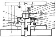
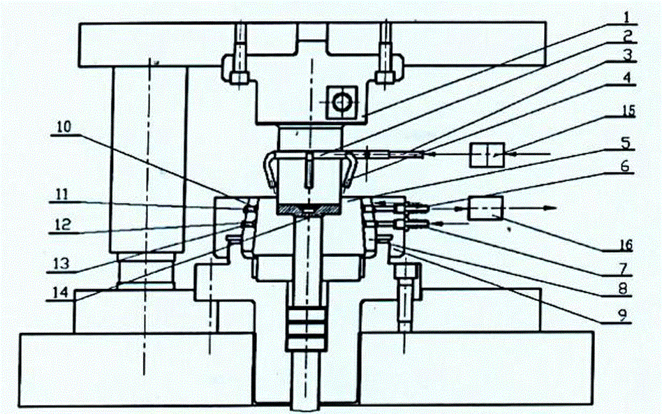
Fig. 1 is a three-dimensional cutaway view of the present utility model;
Fig. 2 is a punch stereogram of the present utility model;
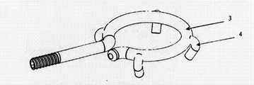
Fig. 3 is cooling tube of the present utility model and nozzle stereogram;
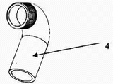
Fig. 4 is a nozzle stereogram of the present utility model;
Fig. 5 is a punch cooling spraying device front view of the present utility model;
Fig. 6 is die cooling body prestressing force inner ring of the present utility model and outer ring assembling half sectional view;
Fig. 7 is that die of the present utility model outer ring inner annular tank and apopore partly cut open three-dimensional view.
Label declaration in the accompanying drawing:
The 1-punch; 2-punch groove; The 3-cooling tube; The 4-nozzle; The 5-die;
6-outer ring delivery port; 7-outer ring water inlet; 8-die inner ring;
9-die outer ring; 10-inner ring annular water tank; 11-inner ring apopore;
12-outer ring annular water tank; 13-inner ring inlet opening; The 14-workpiece;
15-four-way commutation vapour, liquid distributing valve; 16-mould thermostat;
17-outer ring sealing muscle; 18-inner ring sealing muscle;
19-inner ring vertical slot.
The specific embodiment
Below in conjunction with accompanying drawing the utility model is described further.
Warm-extrusion forming equipment for cooling die of the present utility model has adopted spray cooling device to forced punch.
As shown in Figure 1, spray cooling device is installed in the punch below, arranges ringwise, and during work, mist vapour carries out the batch (-type) cooling from several nozzle ejections to punch.The time of cooling is by 15 controls of two four-way commutation vapour-liquid distributing valves.When the slide block upward stroke, two four-way commutation vapour-liquid distributing valves 15 are opened, and the ejection spraying is cooled off punch; When slide block during to down stroke, two four-way commutation vapour-liquid distributing valves 15 cut out, and punch are not cooled off.The position of two four-way commutation vapour-liquid distributing valves 15 is controlled by the travel switch on the forcing press.
In Fig. 2, punch 1 Surface Machining has ring-shaped groove 2, and cooling tube 3 is around being installed on the punch ring-shaped groove 2, and cooling tube 3 is made by copper pipe, and several nozzles 4 are housed on the copper pipe.As Fig. 3 and Fig. 4, shown in nozzle 4 4-5 generally can be set, be installed on the cooling tube 3, be convenient to punch be cooled off from each different angles.Nozzle 4 is made by flexible pipe, and when mounted, nozzle 4 can be adjusted different angles of inclination.The diameter of cooling tube 3 is more smaller (as little by 1 ~ 2mm) than 2 diameters of the ring-shaped groove on the punch 1.Cooling tube 3 can be according to the vapour pressure setting with nozzle 4 pipe thicknesses, general 3-4 mm.
As shown in Figure 6, the die cooling body is provided with shrink ring, is made up of inner ring 8 and outer ring 9, is circular configuration, and die is installed in the inner ring 8, and structurally, the external diameter of outer ring 9 internal diameters and inner ring 8 adopts interference fit to install, and both pressing angles are 1.5 °.
The inwall of outer ring 9 and inner ring 8 is all offered several annular water tanks, and makes an opening through vertical slot and open apopore, make water in outer ring and inner ring inside respectively around several weeks, the heat of taking away die flows into cooling device again.
As shown in Figure 7, outer ring 9 is circular, has dug inlet opening, outer ring 7 thereon, outer ring apopore 6, outer ring annular groove 12 and outer ring sealing muscle 17.
Die inner ring 8 is circular, has dug inner ring annular water tank 10, inner ring vertical slot 19, inner ring apopore 11, inner ring inlet opening 13, inner ring sealing muscle 18 and inner ring vertical slot 19 thereon.
The cross sectional shape of inner ring annular water tank 10, outer ring annular water tank 12 is semicircle or U type or rectangle.
Cooling water is injected by the inlet opening 7 of outer ring during work, ring annular groove 12 outside the warp arrives inner ring inlet opening 13 under the effect of pressure, flows into inner ring annular water tank 10, at inner ring, cooling water around the heat of taking away die in two weeks of die, by the water hole inner ring apopore 11 on inner ring top, flows back to the outer ring tank along water annulus again, after outer ring annular water tank 12 circulates a week once more, flow out from outer ring apopore 6, through pipeline input cooling device, cooling circulates.
In cooling water circulation of the present utility model,, after the shrink ring pressing, can guarantee the sealing of pipeline well owing to this cooling-water duct is out on shrink ring.
In order to reach cooling effect better, the die cooling device has been set up mold temperature controller 16, as shown in fig. 1, when leaving water temperature too high, during expression die temperature drift, strengthen the cooling water flow velocity, to take away more heat, reach the effect that reduces the die temperature, opposite, when the die temperature is on the low side, then reduce the cooling water flow velocity.