CN201848377U - Centrifugal clamp - Google Patents
Centrifugal clamp Download PDFInfo
- Publication number
- CN201848377U CN201848377U CN2010205543425U CN201020554342U CN201848377U CN 201848377 U CN201848377 U CN 201848377U CN 2010205543425 U CN2010205543425 U CN 2010205543425U CN 201020554342 U CN201020554342 U CN 201020554342U CN 201848377 U CN201848377 U CN 201848377U
- Authority
- CN
- China
- Prior art keywords
- sub
- holder
- suspension member
- center
- type suspension
- Prior art date
- Legal status (The legal status is an assumption and is not a legal conclusion. Google has not performed a legal analysis and makes no representation as to the accuracy of the status listed.)
- Expired - Fee Related
Links
- 239000000725 suspension Substances 0.000 claims description 95
- 239000000758 substrate Substances 0.000 claims description 17
- 238000000034 method Methods 0.000 description 4
- 239000003292 glue Substances 0.000 description 3
- 239000008280 blood Substances 0.000 description 2
- 210000004369 blood Anatomy 0.000 description 2
- 230000007812 deficiency Effects 0.000 description 2
- 239000000463 material Substances 0.000 description 2
- 238000002360 preparation method Methods 0.000 description 2
- 239000000084 colloidal system Substances 0.000 description 1
- 238000005538 encapsulation Methods 0.000 description 1
- 238000005516 engineering process Methods 0.000 description 1
- 239000000835 fiber Substances 0.000 description 1
- 230000005484 gravity Effects 0.000 description 1
- 238000001631 haemodialysis Methods 0.000 description 1
- 238000007689 inspection Methods 0.000 description 1
- 210000003734 kidney Anatomy 0.000 description 1
- 238000004519 manufacturing process Methods 0.000 description 1
- 239000002699 waste material Substances 0.000 description 1
Images
Landscapes
- External Artificial Organs (AREA)
Abstract
The utility model discloses a centrifugal clamp, which is provided with a round base plate and a fixing device. The fixing device is provided with one or more sets of fixing seat and U-shaped hanger; each fixing seat is fixedly connected with the corresponding base plate, and each U-shaped hanger is fixed with the corresponding fixing seat; each set of fixing seat comprises a first fixing sub-seat and a second fixing sub-seat which are fixedly connected with the base plate, and the center of each first fixing sub-seat 210, the center of each second fixing sub-seat 220 and the center of the base plate 100 form a plane vertical to the base plate 100; and each set of U-shaped hanger comprises a first U-shaped sub-hanger and a second U-shaped hanger, the first U-shaped sub-hanger is fixed on the first fixing sub-seat, the second U-shaped hanger is fixed on the second fixing sub-seat, and the center of each first U-shaped sub-hanger 310, the center of each second U-shaped sub-hanger 320 and the center of the base plate 100 form a plane vertical to the base plate 100. The centrifugal clamp can be used for tightly clamping a dialyser so as to ensure that the center of the dialyser is consistent with the center of the centrifugal clamp, so that product efficiency is improved.
Description
Technical field
The utility model relates to the dialyzer preparing technical field, particularly relates to a kind of centrifugal anchor clamps that are used for the dialyzer preparation.
Background technology
Dialyzer is commonly called as artificial kidney, has obtained extensive use clinically.By carrying out haemodialysis, life-span that can the proper extension patient.Dialyzer generally includes housing, is arranged at hollow fibre, the blood feed tube that is arranged at the housing two ends, blood drain pipe, dislysate drain pipe and dislysate feed tube in the housing.Dialyzer is in preparation process, and the housing of tunica fibrosa need being packed on inspection, encapsulating, by the two ends encapsulation of two encapsulatings lids with housing, passes through steps such as centrifugal treating then again.The centrifugal treating step can be so that colloid be uniformly distributed in the tunica fibrosa two ends in the dialyzer housing.
In the prior art, mostly the anchor clamps of dialyzer when carrying out centrifugal treating are to adopt spring leaf to push down and install the two ends of the dialyzer of encapsulating lid, and then rotate at a high speed by centrifuge.Because the elasticity and the elastic force of two ends spring leaf are inconsistent, the center that anchor clamps were departed from its center easily when the dialyzer of first-class encapsulating lid was put anchor clamps into, cause the center and the anchor clamps center of dialyzer asymmetric, even the height that the dialyzer two ends also can occur causes the glue amount at dialyzer two ends when centrifugal inhomogeneous with respect to the inconsistent problem of datum level, cause product rejection, bring very big waste to production.
Therefore, at the prior art deficiency, provide a kind of centrifugal anchor clamps very necessary to overcome the prior art weak point.
Summary of the invention
The purpose of this utility model is to avoid the deficiencies in the prior art part and a kind of centrifugal anchor clamps is provided, and uses these centrifugal anchor clamps to carry out dialyzer when centrifugal, can guarantee the center and the centrifugal anchor clamps center symmetry of dialyzer, improves product efficiency.
The purpose of this utility model realizes by following technical measures.
A kind of centrifugal anchor clamps are provided with circular chassis and fixture, and described fixture is arranged at described chassis;
Described fixture is provided with a cover or and overlaps above holder, the U type suspension member that equates with described holder tricks;
Described holder is fixedlyed connected with described chassis, and described U type suspension member is fixedlyed connected with described holder;
The described holder of every cover comprises the first sub-holder and the second sub-holder, the described first sub-holder is fixedlyed connected with described chassis respectively with the second sub-holder, and the center of the center of the described first sub-holder, the described second sub-holder and the plane that the center constituted on described chassis are vertical with described chassis;
The described U type of every cover suspension member comprises the first sub-U type suspension member and the second sub-U type suspension member, the described first sub-U type suspension member is fixed in the described first sub-holder, the described second sub-U type suspension member is fixed in the described second sub-holder, and the plane that the center of the center of the described first sub-U type suspension member, the described second sub-U type suspension member and the center on described chassis constitute is vertical with described chassis.
The holder of described fixture setting evenly distributes and is fixed in described chassis.
Described fixture is provided with two cover holders and two cover U type suspension members;
The first sub-U type suspension member center of two cover U type suspension members and the line at the second sub-U type suspension member center stagger mutually.
The described first sub-U type suspension member is provided with substrate and the holder of U type, and described substrate is fixedlyed connected with the holder of described U type;
The described second sub-U type suspension member is provided with substrate and the holder of U type, and described substrate is fixedlyed connected with the holder of described U type.
Described substrate and the holder of described U type are set to integrated formed structure.
Described holder is fixedlyed connected by screw with described chassis.
Described U type suspension member is fixedlyed connected by screw with described holder.
Described U type suspension member and described holder are set to integrated formed structure.
A kind of centrifugal anchor clamps that the utility model provides are provided with circular chassis and fixture, and described fixture is arranged at described chassis; Described fixture is provided with a cover or and overlaps above holder, the U type suspension member that equates with described holder tricks; Described holder is fixedlyed connected with described chassis, and described U type suspension member is fixedlyed connected with described holder; The described holder of every cover comprises the first sub-holder and the second sub-holder, the described first sub-holder is fixedlyed connected with described chassis respectively with the second sub-holder, and the center of the center of the described first sub-holder, the described second sub-holder and the plane that the center constituted on described chassis are vertical with described chassis; The described U type of every cover suspension member comprises the first sub-U type suspension member and the second sub-U type suspension member, the described first sub-U type suspension member is fixed in the described first sub-holder, the described second sub-U type suspension member is fixed in the described second sub-holder, and the plane that the center of the center of the described first sub-U type suspension member, the described second sub-U type suspension member and the center on described chassis constitute is vertical with described chassis.These centrifugal anchor clamps can clamp dialyzer, and can guarantee that the center of dialyzer is consistent with centrifugal anchor clamps center, improve product efficiency.
Description of drawings
Utilize accompanying drawing that the utility model is further described, but the content in the accompanying drawing does not constitute any restriction of the present utility model.
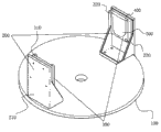
Fig. 1 is the structural representation of a kind of centrifugal anchor clamps of the utility model embodiment 1.
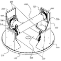
Fig. 2 is the structural representation of a kind of centrifugal anchor clamps of the utility model embodiment 2.
In Fig. 1, Fig. 2, comprising:
First sub-U type suspension member 310, the second sub-U type suspension member 320,
The specific embodiment
The utility model is described in further detail with the following Examples.
Embodiment 1.
A kind of centrifugal anchor clamps as shown in Figure 1, are provided with circular chassis 100 and fixture, and fixture is used for fixing dialyzer, and fixture is arranged at chassis 100 and fixedlys connected with chassis 100.
Fixture is provided with a cover holder 200 and a cover U type suspension member 300.Fixedly connected by screw in holder 200 and chassis 100, U type suspension member 300 and holder 200 are fixedlyed connected by screw.Need to prove that holder 200 can also be fixedlyed connected by riveted joint or other connected modes with chassis 100.U type suspension member 300 also can be fixedlyed connected by other connected modes with holder 200, also can be set to integrated formed structure.
This cover holder 200 comprises the first sub-holder 210 and the second sub-holder 220, the first sub-holder 210 is fixedlyed connected with chassis 100 respectively with the second sub-holder 220, and the center of the center of the first sub-holder 210, the second sub-holder 220 is vertical with chassis 100 with the plane that the center on chassis 100 constitutes.
This cover U type suspension member 300 comprises first sub-U type the suspension member 310 and second sub-U type suspension member 320, the first sub-U type suspension member 310 is fixed in the first sub-holder 210, it is vertical with chassis 100 with the plane that the center constituted on chassis 100 that the second sub-U type suspension member 320 is fixed in the center of center, the second sub-U type suspension member 320 of second sub-holder 220, the first sub-U type suspension members 310.
First sub-U type the suspension member 310 and second sub-U type suspension member 320 of U type suspension member 300 is respectively arranged with substrate 400 and U type holder 500, and substrate 400 is fixedlyed connected with U type holder 500.Substrate 400 is set to integrated formed structure with U type holder 500.
Centrifugal anchor clamps of the present utility model, its use is such, and the dialyzer that installs encapsulating lid is arranged on the fixture of these centrifugal anchor clamps, the two ends of dialyzer cooperate the U type holder 500 that is installed in first sub-U type the suspension member 310 and second sub-U type suspension member 320 respectively.The length of dialyzer is longer a little than the distance between the U type holder 500 of U type the holder 500 and second sub-U type suspension member 320 of the first sub-U type suspension member 310, like this, utilize the plasticity of dialyzer material, with after the dialyzer assembling, the dialyzer two ends can with two U types holder, 500 secure of U type suspension member 300.And the structural design of U type holder 500 can contact just with the dialyzer end, prevents that shaking phenomenon appears in dialyzer in the centrifugal treating process.Therefore, these centrifugal anchor clamps can clamp dialyzer in the centrifugal treating process.
Because the plane that the center on the center of the first sub-holder 210, the center of the second sub-holder 220 and chassis 100 constitutes is vertical with chassis 100, the center of the center of the first sub-U type suspension member 310, the second sub-U type suspension member 320 is vertical with chassis 100 with the plane that the center constituted on chassis 100.After dialyzer is positioned over these centrifugal anchor clamps, can guarantee the two ends height unanimity of dialyzer, and the center of dialyzer and this centrifugal anchor clamps center be consistent, thereby the glue amount that guarantees dialyzer two ends in centrifugal treating is even, the raising product percent of pass.
In addition, centrifugal clamp structure of the present utility model is simple, with low cost.
Embodiment 2.
A kind of centrifugal anchor clamps as shown in Figure 2, are provided with circular chassis 100 and fixture, and fixture is used for fixing dialyzer 600, and fixture is arranged at chassis 100 and fixedlys connected with chassis 100.
Fixture is provided with two cover holders 200 and two cover U type suspension members 300.Holder 200 is used for fixedlying connected with chassis 100, and U type suspension member 300 is used for fixing dialyzer 600, and U type suspension member 300 could be realized fixedly dialyzer 600 by being fixed on holder 200, and therefore, the tricks of U type suspension member 300 is consistent with the tricks of holder 200.Center of gravity is firm when making centrifugal treating, and holder 200 evenly distributes and is fixed in chassis 100.
Fixedly connected by screw in holder 200 and chassis 100, U type suspension member 300 and holder 200 are fixedlyed connected by screw.Need to prove that holder 200 can also be fixedlyed connected by riveted joint or other connected modes with chassis 100.U type suspension member 300 also can be fixedlyed connected by other connected modes with holder 200, also can be set to integrated formed structure.
Every cover holder 200 comprises the first sub-holder 210 and the second sub-holder 220, the first sub-holder 210 is fixedlyed connected with chassis 100 respectively with the second sub-holder 220, and the center of the center of the first sub-holder 210, the second sub-holder 220 is vertical with chassis 100 with the plane that the center on chassis 100 constitutes.
Every cover U type suspension member 300 comprises first sub-U type the suspension member 310 and second sub-U type suspension member 320, the first sub-U type suspension member 310 is fixed in the first sub-holder 210, it is vertical with chassis 100 with the plane that the center constituted on chassis 100 that the second sub-U type suspension member 320 is fixed in the center of center, the second sub-U type suspension member 320 of second sub-holder 220, the first sub-U type suspension members 310.
First sub-U type suspension member 310 centers of two cover U type suspension members 300 and the line at the second sub-U type suspension member, 320 centers stagger mutually, guarantee to be interspersed between the dialyzer 600 after two dialyzers 600 assemble simultaneously.
First sub-U type the suspension member 310 and second sub-U type suspension member 320 of U type suspension member 300 is respectively arranged with substrate 400 and U type holder 500, and substrate 400 is fixedlyed connected with U type holder 500.Substrate 400 is set to integrated formed structure with U type holder 500.
Centrifugal anchor clamps of the present utility model, be to use like this, two dialyzers 600 that install encapsulating lid are separately positioned on two cover U type suspension members 300 of this centrifugal anchor clamps fixture, and the two ends of dialyzer 600 cooperate the U type holder 500 that is installed in first sub-U type the suspension member 310 and second sub-U type suspension member 320 respectively.The length of dialyzer 600 is longer a little than the distance between the U type holder 500 of U type the holder 500 and second sub-U type suspension member 320 of the first sub-U type suspension member 310, like this, utilize the plasticity of dialyzer 600 materials, after dialyzer 600 assembling, dialyzer 600 two ends can with two U types holder, 500 secure of U type suspension member 300.And the structural design of U type holder 500 can contact just with dialyzer 600 ends, prevents that in the centrifugal treating process, shaking phenomenon appears in dialyzer 600.Therefore, these centrifugal anchor clamps can clamp dialyzer 600 in the centrifugal treating process.
Because the plane that the center on the center of the first sub-holder 210, the center of the second sub-holder 220 and chassis 100 constitutes is vertical with chassis 100, the center of the center of the first sub-U type suspension member 310, the second sub-U type suspension member 320 is vertical with chassis 100 with the plane that the center constituted on chassis 100.After dialyzer 600 is positioned over these centrifugal anchor clamps, can guarantee the two ends height unanimity of dialyzer 600, and the center of dialyzer 600 is consistent with this centrifugal anchor clamps center, thereby the glue amount that guarantees dialyzer 600 two ends in centrifugal treating is even, improves product percent of pass.
Two cover holders 200 and two overlap the design of U type suspension members 300, can once carry out the centrifugal treating of two dialyzers 600, can further enhance productivity.In addition, centrifugal clamp structure of the present utility model is simple, with low cost.
Need to prove that holder 200 that centrifugal anchor clamps of the present utility model are set and U type suspension member 300 are not limited only to two covers in the present embodiment, also can according to actual conditions be set to 3 the cover or 3 the cover more than.
Should be noted that at last; above embodiment is only in order to the explanation the technical solution of the utility model but not to the restriction of the utility model protection domain; although the utility model has been done detailed description with reference to preferred embodiment; those of ordinary skill in the art is to be understood that; can make amendment or be equal to replacement the technical solution of the utility model, and not break away from the essence and the scope of technical solutions of the utility model.
Claims (8)
1. centrifugal anchor clamps is characterized in that:
Be provided with circular chassis and fixture, described fixture is arranged at described chassis;
Described fixture is provided with a cover or and overlaps above holder, the U type suspension member that equates with described holder tricks;
Described holder is fixedlyed connected with described chassis, and described U type suspension member is fixedlyed connected with described holder;
The described holder of every cover comprises the first sub-holder and the second sub-holder, the described first sub-holder is fixedlyed connected with described chassis respectively with the second sub-holder, and the center of the center of the described first sub-holder, the described second sub-holder and the plane that the center constituted on described chassis are vertical with described chassis;
The described U type of every cover suspension member comprises the first sub-U type suspension member and the second sub-U type suspension member, the described first sub-U type suspension member is fixed in the described first sub-holder, the described second sub-U type suspension member is fixed in the described second sub-holder, and the plane that the center of the center of the described first sub-U type suspension member, the described second sub-U type suspension member and the center on described chassis constitute is vertical with described chassis.
2. according to the described centrifugal anchor clamps of claim 1, it is characterized in that: the holder of described fixture setting evenly distributes and is fixed in described chassis.
3. centrifugal anchor clamps according to claim 1 and 2 is characterized in that: described fixture is provided with two cover holders and two cover U type suspension members;
The first sub-U type suspension member center of two cover U type suspension members and the line at the second sub-U type suspension member center stagger mutually.
4. centrifugal anchor clamps according to claim 3 is characterized in that: the described first sub-U type suspension member is provided with substrate and the holder of U type, and described substrate is fixedlyed connected with the holder of described U type;
The described second sub-U type suspension member is provided with substrate and the holder of U type, and described substrate is fixedlyed connected with the holder of described U type.
5. centrifugal anchor clamps according to claim 4 is characterized in that: described substrate and the holder of described U type are set to integrated formed structure.
6. centrifugal anchor clamps according to claim 1 is characterized in that: described holder is fixedlyed connected by screw with described chassis.
7. centrifugal anchor clamps according to claim 1 is characterized in that: described U type suspension member is fixedlyed connected by screw with described holder.
8. centrifugal anchor clamps according to claim 1 is characterized in that: described U type suspension member and described holder are set to integrated formed structure.
Priority Applications (1)
| Application Number | Priority Date | Filing Date | Title |
|---|---|---|---|
| CN2010205543425U CN201848377U (en) | 2010-10-09 | 2010-10-09 | Centrifugal clamp |
Applications Claiming Priority (1)
| Application Number | Priority Date | Filing Date | Title |
|---|---|---|---|
| CN2010205543425U CN201848377U (en) | 2010-10-09 | 2010-10-09 | Centrifugal clamp |
Publications (1)
| Publication Number | Publication Date |
|---|---|
| CN201848377U true CN201848377U (en) | 2011-06-01 |
Family
ID=44090791
Family Applications (1)
| Application Number | Title | Priority Date | Filing Date |
|---|---|---|---|
| CN2010205543425U Expired - Fee Related CN201848377U (en) | 2010-10-09 | 2010-10-09 | Centrifugal clamp |
Country Status (1)
| Country | Link |
|---|---|
| CN (1) | CN201848377U (en) |
-
2010
- 2010-10-09 CN CN2010205543425U patent/CN201848377U/en not_active Expired - Fee Related
Similar Documents
| Publication | Publication Date | Title |
|---|---|---|
| CN201848377U (en) | Centrifugal clamp | |
| CN202245312U (en) | Novel clamp for loading and unloading plastic bottles automatically on disc | |
| CN201783243U (en) | Vacuum suction filtration tank | |
| CN202397160U (en) | Novel shoe airing frame | |
| CN203971010U (en) | The centrifugal glue injection frame of a kind of dialyser | |
| CN103706254B (en) | A kind of hollow-fibre membrane membrane module and method for packing thereof | |
| CN201916290U (en) | Sterilizer, lamp holder bracket and its connecting device | |
| CN202688427U (en) | Indentation-free full-aperture coating fixture for lens | |
| CN208523393U (en) | A kind of adjustable municipal tree fixed mount | |
| CN204330767U (en) | A kind of acetate fiber membrane carrier setting egg(s) white antibody incubation Binding experiment device | |
| CN201658987U (en) | Shockproof easy-placing test-tube rack | |
| CN203829929U (en) | Penetration assisting device | |
| CN208529779U (en) | The fixed structure of filter membrane in a kind of medical instrument | |
| CN203971011U (en) | A kind of dialyser spiral cover | |
| CN216205160U (en) | Lens baking basket | |
| CN206617571U (en) | High-pressure bottle top cover opening device | |
| CN215046200U (en) | Device for automatically overturning cylindrical material | |
| CN206449567U (en) | Emergent down lamp | |
| CN203231160U (en) | Combined table lamp with photo frames | |
| CN204574572U (en) | A kind of solar thermal collector and framework thereof | |
| CN201482573U (en) | Centrifuger and centrifuger hanging rack | |
| CN219215909U (en) | Adjustable non-contact optical element packing carton | |
| CN202314340U (en) | Transfusion bottle | |
| CN220351712U (en) | Paint paper funnel that insulating property is good | |
| CN218834125U (en) | A microdialyzer for purification of nanomaterials |
Legal Events
| Date | Code | Title | Description |
|---|---|---|---|
| C14 | Grant of patent or utility model | ||
| GR01 | Patent grant | ||
| CF01 | Termination of patent right due to non-payment of annual fee | ||
| CF01 | Termination of patent right due to non-payment of annual fee |
Granted publication date: 20110601 Termination date: 20161009 |