CN201848372U - Two-component glue sizing machine - Google Patents
Two-component glue sizing machine Download PDFInfo
- Publication number
- CN201848372U CN201848372U CN 201020586238 CN201020586238U CN201848372U CN 201848372 U CN201848372 U CN 201848372U CN 201020586238 CN201020586238 CN 201020586238 CN 201020586238 U CN201020586238 U CN 201020586238U CN 201848372 U CN201848372 U CN 201848372U
- Authority
- CN
- China
- Prior art keywords
- glue
- cylinder
- glue pump
- pump
- swing arm
- Prior art date
- Legal status (The legal status is an assumption and is not a legal conclusion. Google has not performed a legal analysis and makes no representation as to the accuracy of the status listed.)
- Expired - Lifetime
Links
- 239000003292 glue Substances 0.000 title claims abstract description 95
- 238000004513 sizing Methods 0.000 title abstract 4
- 230000008676 import Effects 0.000 claims description 10
- 239000000725 suspension Substances 0.000 claims description 9
- 238000004026 adhesive bonding Methods 0.000 claims description 8
- 230000002457 bidirectional effect Effects 0.000 abstract 5
- 239000000084 colloidal system Substances 0.000 description 15
- 230000001105 regulatory effect Effects 0.000 description 4
- 238000002156 mixing Methods 0.000 description 2
- 239000000853 adhesive Substances 0.000 description 1
- 230000001070 adhesive effect Effects 0.000 description 1
- 230000009286 beneficial effect Effects 0.000 description 1
- 239000011248 coating agent Substances 0.000 description 1
- 238000000576 coating method Methods 0.000 description 1
- 239000012530 fluid Substances 0.000 description 1
- 238000012856 packing Methods 0.000 description 1
- 239000000565 sealant Substances 0.000 description 1
Images
Landscapes
- Coating Apparatus (AREA)
Abstract
The utility model discloses a two-component glue sizing machine, comprising a machine frame, a glue bucket A, a glue pump A, a bidirectional oil cylinder, a proportion adjusting mechanism, a glue pump B pressurizing cylinder and a glue pump B, wherein the inlet of the glue pump A is connected with the glue bucket A; the inlet of the glue pump pressurizing cylinder B is connected with the glue pump B; the cylinder body of the bidirectional oil cylinder is fixed above the pump body of the glue pump A; the cylinder body of the bidirectional oil cylinder is fixed with the machine frame; the proportion adjusting mechanism comprises a proportion system mounting plate, a support seat, a swing arm and a hinge; and the cylinder body of the glue pump B pressurizing cylinder and the cylinder body of the bidirectional oil cylinder are respectively fixed with the proportion system mounting plate. The utility model uses one bidirectional oil cylinder to drive the two glue extruding devices to work, then the two glues can be mixed and output to the glue sizing system in certain proportion, and the glue extruding quantity of the glue pump B pressurizing cylinder is adjusted through adjusting the proportion adjusting mechanism, therefore, the proportion can be properly adjusted. The two-component glue sizing machine has reliable structure and is convenient to adjust.
Description
Technical field
The utility model relates to a kind of colloid conveyer, particularly a kind of two-component gluing machine.
Background technology
Along with the double glazing industry, the development of automobile industry, the double glazing of large format, hollow curtain wall, engine cylinder cover, packings such as automobile door periphery, coating fluid sealant become the industry important step.Design two component A, B become the requisite important key equipment of industry gradually from the equipment of dried glue.How to try every possible means the two component glue of A, B are mixed output to by a certain percentage and beat colloid system, and resize ratio size in right amount, be urgency problem to be solved in the industry.
Summary of the invention
Problem to be solved in the utility model is: a kind of two-component gluing machine is provided, it can be mixed output to two kinds of colloids by a certain percentage beats colloid system, and resize ratio size in right amount.For addressing the above problem, the utility model comprises frame, A glue bucket, A glue pump, two-way cylinder, the ratio guiding mechanism, B glue pump pressurized cylinder and B glue pump, the import of A glue pump connects A glue bucket, the import of B glue pump pressurized cylinder connects B glue pump, the cylinder body of two-way cylinder is fixed on the top of the pump housing of A glue pump, the cylinder body and the frame of two-way cylinder fix, the ratio guiding mechanism comprises the ratio system installing plate, supporting seat, swing arm and chain link, the cylinder body of B glue pump pressurized cylinder and the cylinder body of two-way cylinder all fix with the ratio system installing plate, the piston rod of the lower piston rod of two-way cylinder and A glue pump fixes, the upper piston rod of two-way cylinder is connected with an end of swing arm by a chain link, the piston rod of B glue pump pressurized cylinder is connected with the other end of swing arm by another chain link, what the supporting seat lower end position was adjustable is arranged on the ratio system installing plate, and the upper end and the swing arm of supporting seat are slidingly connected.Regulate the position of piston rod in swing arm of B glue pump pressurized cylinder for convenience, the upper end of described supporting seat is connected by mobile hinge with swing arm, and the mobile hinge chain is enclosed within the swing arm, and supporting seat and mobile hinge are hinged.Inhale glue for the ease of A glue pump from A glue bucket, described frame comprises base, suspension bracket and lift cylinder, and lift cylinder is arranged between base and the suspension bracket, and the cylinder body of two-way cylinder is fixed on the below of suspension bracket, and the import of A glue pump is connected with A glue bucket by inhaling the glue laminated dish.For the ease of regulating the position of supporting seat, described supporting seat is connected by bolt and nut with the ratio system installing plate, and bolt mounting holes is the slotted hole that length is extended in the pendulum arm length direction on the ratio system installing plate.For the ease of the flow direction of control colloid, the suction Jiao Kou of described suction glue laminated dish is provided with check valve, and the import of B glue pump pressurized cylinder is provided with check valve.The beneficial effects of the utility model: the utility model drives two by a two-way cylinder and goes out adhesive dispenser work, it can be mixed output to two kinds of colloids by a certain percentage beat colloid system, regulate the gel quantity of B glue pump pressurized cylinder by regulating the ratio guiding mechanism, thereby realize an amount of resize ratio size.And the utility model reliable in structure, easy to adjust.
Description of drawings
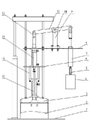
Fig. 1 is a structural representation of the present utility model; Among the figure, 1, frame, 2, A glue bucket, 3, inhale the glue laminated dish, 4, B glue pump, 5, check valve, 6, fixing panel seat, 7, B glue pump pressurized cylinder, 8, the ratio system installing plate, 9, supporting seat, 10, mobile hinge, 11, swing arm, 12, chain link, 13, two-way cylinder, 14, column, 15, A glue pump.
The specific embodiment
A kind of specific embodiment as shown in Figure 1, it comprises frame 1, A glue bucket 2, inhales glue laminated dish 3, B glue pump 4, check valve 5, fixedly panel seat 6, B glue pump pressurized cylinder 7, ratio system installing plate 8, supporting seat 9, mobile hinge 10, swing arm 11, chain link 12, two-way cylinder 13, column 14 and A glue pump 15.Described frame 1 comprises base, suspension bracket and lift cylinder, and lift cylinder is arranged between base and the suspension bracket, and the import of A glue pump 15 is connected with A glue bucket 2 by inhaling glue laminated dish 3, and the suction Jiao Kou that inhales glue laminated dish 3 is provided with check valve.Inhaling glue laminated dish 3 hangs below suspension bracket by several root posts, fixedly panel seat 6 and ratio system installing plate 8 all are horizontally fixed on the aforesaid column, ratio system installing plate 8 is positioned at the fixedly top of panel seat 6, the pump housing of A glue pump 15 is hung below fixing panel seat 6 by column 14, the cylinder body of two-way cylinder 13 is fixed on fixedly between the panel seat 6 and ratio system installing plate 8, the cylinder body of B glue pump pressurized cylinder 7 is fixed on the downside of ratio system installing plate 8,7 imports of B glue pump pressurized cylinder connect B glue pump 4 by check valve 5, B glue pump 4 is that B glue pump pressurized cylinder 7 is for glue, the piston rod of the lower piston rod of two-way cylinder 13 and A glue pump 15 fixes, the upper piston rod of two-way cylinder 13 is connected with an end of swing arm 11 by a chain link 12, the piston rod of B glue pump pressurized cylinder 7 is connected with the other end of swing arm 11 by another chain link 12, the connected mode of the attachment at two chain links 12 and its two ends is hinged, supporting seat 9 is between the piston rod of the upper piston rod of two-way cylinder 13 and B glue pump pressurized cylinder 7, and the upper end of supporting seat 9 is connected by mobile hinge 10 with swing arm 11.Mobile hinge 10 is a cylindrical shell, and the middle part of cylindrical shell is provided with axle overhanging and that directly make progress at cylindrical shell, and mobile hinge 10 is enclosed within the swing arm 11, and supporting seat 9 is rotatably connected with the axle of mobile hinge 10.The lower end of supporting seat 9 is installed on the ratio system installing plate 8 by bolt and nut, and bolt mounting holes is the slotted hole that length is extended at swing arm 11 length directions on the ratio system installing plate 8.Regulate the position of supporting seat 9 by regulating the position of bolt in slotted hole, adjust the back fastening nut and can lock supporting seat 9.Operation principle: when the piston rod of two-way cylinder 13 is up, the piston rod that drives A glue pump 15 is up, A colloid in the A glue bucket 2 is pressed into A glue pump 15, descending by the piston rod of swing arm 11 drive B glue pump B glue pump pressurized cylinder 7 simultaneously, glue blending device is exported and sent into to the B colloid of B glue pump pressurized cylinder 7, when the piston rod of two-way cylinder 13 is descending, A glue pump 15 output A colloids are also sent into glue blending device, B glue pump pressurized cylinder 7 sucks the B colloid, when the fixed-site of supporting seat 9, A colloid and B colloid that a stroke of two-way cylinder 13 extrudes are quantitative, by regulating the position of supporting seat 9, can regulate the gel quantity of a stroke of B glue pump pressurized cylinder, thereby realize the adjustment of A colloid and B colloid mixed proportion.
Claims (5)
1. two-component gluing machine, it is characterized in that: comprise frame (1), A glue bucket (2), A glue pump (15), two-way cylinder (13), the ratio guiding mechanism, B glue pump pressurized cylinder (7) and B glue pump (4), the import of A glue pump (15) connects A glue bucket (2), B glue pump pressurized cylinder (7) import connects B glue pump (4), the cylinder body of two-way cylinder (13) is fixed on the top of the pump housing of A glue pump (15), the cylinder body of two-way cylinder (13) and frame (1) fix, the ratio guiding mechanism comprises ratio system installing plate (8), supporting seat (9), swing arm (11) and chain link (12), the cylinder body of the cylinder body of B glue pump pressurized cylinder (7) and two-way cylinder (13) all fixes with ratio system installing plate (8), the piston rod of the lower piston rod of two-way cylinder (13) and A glue pump (15) fixes, the upper piston rod of two-way cylinder (13) is connected with an end of swing arm (11) by a chain link (12), the piston rod of B glue pump pressurized cylinder (7) is connected with the other end of swing arm (11) by another chain link (12), what supporting seat (9) lower end position was adjustable is arranged on the ratio system installing plate (8), and the upper end of supporting seat (9) and swing arm (11) are slidingly connected.
2. two-component gluing machine according to claim 1, it is characterized in that: the upper end of described supporting seat (9) is connected by mobile hinge (10) with swing arm (11), mobile hinge (10) is enclosed within the swing arm (11), and supporting seat (9) is hinged with mobile hinge (10).
3. two-component gluing machine according to claim 1 and 2, it is characterized in that: described frame (1) comprises base, suspension bracket and lift cylinder, lift cylinder is arranged between base and the suspension bracket, the cylinder body of two-way cylinder (13) is fixed on the below of suspension bracket, and the import of A glue pump (15) is connected with A glue bucket (2) by inhaling glue laminated dish (3).
4. two-component gluing machine according to claim 3, it is characterized in that: described supporting seat (9) is connected by bolt and nut with ratio system installing plate (8), and it is the slotted hole that length is extended at swing arm (11) length direction that ratio system installing plate (8) is gone up bolt mounting holes.
5. two-component gluing machine according to claim 3 is characterized in that: the suction Jiao Kou of described suction glue laminated dish (3) is provided with check valve, and the import of B glue pump pressurized cylinder (7) is provided with check valve (5).
Priority Applications (1)
| Application Number | Priority Date | Filing Date | Title |
|---|---|---|---|
| CN 201020586238 CN201848372U (en) | 2010-11-02 | 2010-11-02 | Two-component glue sizing machine |
Applications Claiming Priority (1)
| Application Number | Priority Date | Filing Date | Title |
|---|---|---|---|
| CN 201020586238 CN201848372U (en) | 2010-11-02 | 2010-11-02 | Two-component glue sizing machine |
Publications (1)
| Publication Number | Publication Date |
|---|---|
| CN201848372U true CN201848372U (en) | 2011-06-01 |
Family
ID=44090786
Family Applications (1)
| Application Number | Title | Priority Date | Filing Date |
|---|---|---|---|
| CN 201020586238 Expired - Lifetime CN201848372U (en) | 2010-11-02 | 2010-11-02 | Two-component glue sizing machine |
Country Status (1)
| Country | Link |
|---|---|
| CN (1) | CN201848372U (en) |
Cited By (1)
| Publication number | Priority date | Publication date | Assignee | Title |
|---|---|---|---|---|
| CN101966512A (en) * | 2010-11-02 | 2011-02-09 | 济南德佳玻璃机器有限公司 | Double-component glue extruder |
-
2010
- 2010-11-02 CN CN 201020586238 patent/CN201848372U/en not_active Expired - Lifetime
Cited By (1)
| Publication number | Priority date | Publication date | Assignee | Title |
|---|---|---|---|---|
| CN101966512A (en) * | 2010-11-02 | 2011-02-09 | 济南德佳玻璃机器有限公司 | Double-component glue extruder |
Similar Documents
| Publication | Publication Date | Title |
|---|---|---|
| CN101966512B (en) | Double-component glue extruder | |
| CN201494656U (en) | Swing type film feeding mechanism of packaging machine | |
| CN204587420U (en) | A kind of mechanical quantitative cylinder bottle placer | |
| CN201848372U (en) | Two-component glue sizing machine | |
| CN211613261U (en) | Automatic gluing mechanism for cylindrical outer wall | |
| CN202671168U (en) | Overhead platform working truck | |
| CN2808860Y (en) | Hoisting arm for crane | |
| CN208678970U (en) | An adhesive dispersing device | |
| CN205896900U (en) | Novel infrared intelligent control ceiling lamp | |
| CN210343687U (en) | Intelligent variable pump | |
| CN101972733B (en) | Colloid proportional transportation device | |
| CN2743225Y (en) | Transfusion bag filling mechanism | |
| CN205871625U (en) | Swivel chair is with truckle fixed and that remove of being convenient for | |
| CN201744433U (en) | Rubber proportional conveyer device | |
| CN201136149Y (en) | Mechanical arm of liquid-auto-dropping machine | |
| CN105944619B (en) | The epoxy resin of variable proportion measures device | |
| CN201254418Y (en) | Chassis apparatus of construction hoist | |
| CN108302031A (en) | A kind of current stabilization hydraulic pump and a kind of current stabilization Transmission system using the current stabilization hydraulic pump | |
| CN204384855U (en) | A kind of loading amount self-checking device being applied to Soup filling machine | |
| CN208293213U (en) | A kind of sewing machine and its automatic connecting rod of falling feeding | |
| CN201849820U (en) | Double-component viscous material proportion conveying mechanism | |
| CN221537138U (en) | Glue valve rotating mechanism | |
| CN217232980U (en) | Iron tower cross arm stores pylon | |
| CN215823515U (en) | Gluing equipment for inner support frame of festive lantern | |
| CN201459375U (en) | Middle presser hoisting structure for sewing of pattern sewing machine |
Legal Events
| Date | Code | Title | Description |
|---|---|---|---|
| C14 | Grant of patent or utility model | ||
| GR01 | Patent grant | ||
| AV01 | Patent right actively abandoned |
Granted publication date: 20110601 Effective date of abandoning: 20120208 |