CN201848365U - Combining body of two serially connected industrial robots - Google Patents

Combining body of two serially connected industrial robots Download PDF

Info

Publication number
CN201848365U
CN201848365U CN2010205071960U CN201020507196U CN201848365U CN 201848365 U CN201848365 U CN 201848365U CN 2010205071960 U CN2010205071960 U CN 2010205071960U CN 201020507196 U CN201020507196 U CN 201020507196U CN 201848365 U CN201848365 U CN 201848365U
Authority
CN
China
Prior art keywords
manipulator
robot
assemblys
utility
model
Prior art date
Legal status (The legal status is an assumption and is not a legal conclusion. Google has not performed a legal analysis and makes no representation as to the accuracy of the status listed.)
Expired - Lifetime
Application number
CN2010205071960U
Other languages
Chinese (zh)
Inventor
A·克罗吉达尔
Current Assignee (The listed assignees may be inaccurate. Google has not performed a legal analysis and makes no representation or warranty as to the accuracy of the list.)
ABB Technology AG
Original Assignee
ABB Technology AG
Priority date (The priority date is an assumption and is not a legal conclusion. Google has not performed a legal analysis and makes no representation as to the accuracy of the date listed.)
Filing date
Publication date
Application filed by ABB Technology AG filed Critical ABB Technology AG
Priority to CN2010205071960U priority Critical patent/CN201848365U/en
Application granted granted Critical
Publication of CN201848365U publication Critical patent/CN201848365U/en
Anticipated expiration legal-status Critical
Expired - Lifetime legal-status Critical Current

Links

Images

Landscapes

  • Manipulator (AREA)
  • Spray Control Apparatus (AREA)

Abstract

本实用新型涉及一种两个串联工业机器人的组合体,该组合体包括串联装配的第一和第二机械手。通过串联装配标准喷涂机器人与SCARA机器人,扩大了标准喷涂机器人的工作空间。组合体进行操纵以喷涂货车箱体的内部。

Figure 201020507196

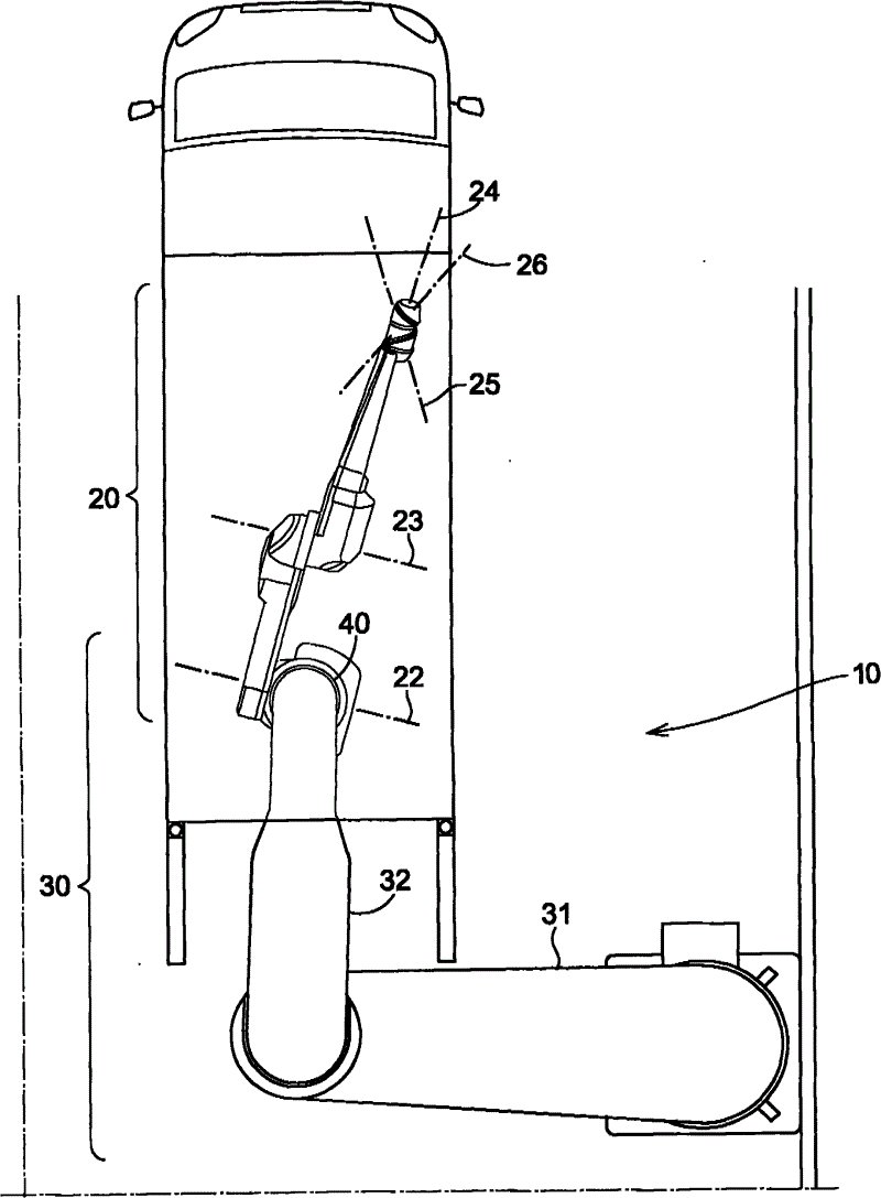
The utility model relates to a combination of two industrial robots in series, which comprises first and second manipulators assembled in series. By assembling the standard painting robot and the SCARA robot in series, the working space of the standard painting robot is expanded. The assembly is maneuvered to paint the interior of the truck box.

Figure 201020507196

Description

The assembly of two series connection industrial robots
Technical field
The utility model relates to a kind of industrial robot or manipulator.Enlarge the working space of manipulator by two or more manipulators of assembled in series.
Background technology
The working space of manipulator is limited by its Machine Design.The main design factor that influences working space has the constraint of the number and the axle of the length of arm, axle.Depend on predetermined purposes, different manipulators is of different sizes and the different frees degree.Can give the many frees degree of spray robot usually from outside and each inner possible angle spray paint of the complex work object of for example body of a motor car in order to make Spray painting tool.Yet in some special application, the working space of traditional spray robot is not enough.A this application is the inside of spraying lorry.Because the working space of standard spray robot is not enough to pass the back door and enters the lorry container and arrive all internal surfaces, so lorry inside hand spray normally.
Certainly, in theory by the length of adjusting arm or the working space that can easily enlarge spray robot by the number that increases arm.May have a kind of robot, this robot can arrive the inside of lorry and in order to spray inside even can to control the required free degree.WO 01/51259 discloses a kind of modularization robot, and it has suitable dimensions, seems the task of can bear the lorry spraying.But many traditional spray robots can not be born this task.Revising the task that existing robots is used to bear the lorry spraying will need suitable technical work and will become very expensive.The robot that exploitation is used for this special applications may prove and not be profitable.The robot of lorry spraying task is born in acquisition also may be than the expensive manyfold of the standard of acquisition spray robot.Therefore, continue to use the hand spray normally attractive selection in lorry inside.
The utility model content
A purpose of the present utility model is to provide a kind of manipulator of bearing lorry internal spray task in useful mode.
This purpose is by realizing according to equipment of the present utility model and method.
The utility model is based on the working space of realizing enlarging the standard mechanical hand by tandem compound manipulator and another standard mechanical hand.
According to first aspect of the present utility model, a kind of manipulator assembly is provided, it comprises first and second manipulators, the first and second manipulator assembled in series.By two manipulators of assembled in series, do not need to redesign the working space that any existing mechanical hand just can enlarge the standard mechanical hand.
According to an embodiment of the present utility model, the first and second manipulator boths are configured to independent operation.
According to an embodiment of the present utility model, between first and second manipulators, exist to have fixedly connected interface.By provide fixedly connected between them, any one function separately that does not need to influence in them just can easily be dismantled manipulator.
According to an embodiment of the present utility model, second manipulator is attached to the final stage arm of first manipulator.
According to an embodiment of the present utility model, mechanical movement is not transmitted at least one interface between two manipulators relatively.
According to an embodiment of the present utility model, the first and second manipulator boths are industrial robots.
According to an embodiment of the present utility model, first manipulator is that 2 axis robot and second manipulator are 6 axis robot.
According to an embodiment of the present utility model, first manipulator is the SCARA robot.
According to an embodiment of the present utility model, second manipulator is the standard spray robot.
According to an embodiment of the present utility model, assembly further comprises the 3rd or even multi-robot more.
According to second aspect of the present utility model, provide a kind of method that enlarges Manipulator Workspace.This method comprises provides first manipulator that is configured to independent operation, and second manipulator that is configured to independent operation is provided, and they make up the step of first and second manipulators by assembled in series.
According to the third aspect of the present utility model, the assembly of manipulator and corresponding method are applied to spray lorry inside.
Description of drawings
Explain the utility model with reference to the accompanying drawings in more detail, wherein:
Fig. 1 shows the manipulator assembly according to an embodiment of the present utility model,
Fig. 2 shows the assembly among the Fig. 1 that arrives lorry inside.
The specific embodiment
With reference to Fig. 1, the assembly 10 of two robots has 6 standard spray robots 20, itself and 2 SCARA robot 30 assembled in series.The SCARA robot has two rocking arms 31,32, and it is 33,34 rotatable that these two rocking arms wave axle about first and second, and spray robot is connected to the end of second rocking arm 32.First 21 yaw motion that allows about the end of second rocking arm of spray robot.Second and the 3rd 22,23 of spray robot allows the motion of bowing of facing upward in being parallel to first plane.The the 4th, the 5th and the 6th 24,25,26 of spray robot form wrist, it allows to face upward and bows, deflection and rolling.
The working space of an independent spray robot is not enough to bear the task of lorry spraying.Yet, carry out the work in combination space with the SCARA robot and on the x-y plane of Fig. 1, significantly enlarge.Can select the size of SCARA robot to be used for preset task suitably, and spray robot is compared and can be had relative suitable dimensions with the rocking arm size of SCARA robot.
SCARA robot and spray robot both are the standard industry robots, and they are configured to independent operation, and be just, independently of one another.This means that two robots can be disassembled at any time, and the self-control robot that obtains can be used for the independent new task of carrying out by reprogramming.Because two robots are configured to independent operation, have an interface 40 between them at least, interface is not movable but fixedly connected.To such an extent as to two robots neither mechanically interrelate and dismantle two robots and will influence any one function separately in them.Especially, mechanical movement is not transmitted at least one interface between two robots relatively.Yet cable, flexible pipe, pipeline and analog can be used for electric energy, compressed air, coating etc. are delivered to spray robot by the interface between SCARA robot and two robots.
The motion of two robot assemblys can be by a common controller control, and perhaps each robot can have the controller of oneself.In the later case, need the controller of higher level to be used to realize be in the motion of the assembly of cooperative mode.
The embodiment that the utility model is not limited to illustrate above, but those skilled in the art can revise them certainly in many ways in as the scope of the present utility model that claims limited.Thereby for example, the utility model is not limited to the assembly of two manipulators, but three or more manipulators of assembled in series in the corresponding way.

Claims (10)

1. manipulator assembly comprises:
First manipulator,
Second manipulator,
It is characterized in that the described first and second manipulator assembled in series.
2. assembly according to claim 1 is characterized in that, the described first and second manipulator boths are configured to independent operation.
3. according to claims 1 or 2 described assemblys, it is characterized in that, between described first and second manipulators, exist to have fixedly connected interface.
4. according to claims 1 or 2 described assemblys, it is characterized in that described second manipulator is connected to the final stage arm of described first manipulator.
5. according to claims 1 or 2 described assemblys, it is characterized in that mechanical movement is not transmitted at least one interface between two manipulators relatively.
6. according to claims 1 or 2 described assemblys, it is characterized in that the described first and second manipulator boths are industrial robots.
7. according to claims 1 or 2 described assemblys, it is characterized in that described first manipulator is 2 axis robot, and second manipulator is 6 axis robot.
8. according to claims 1 or 2 described assemblys, it is characterized in that described first manipulator is the SCARA robot.
9. according to claims 1 or 2 described assemblys, it is characterized in that described second manipulator is the standard spray robot.
10. according to claims 1 or 2 described assemblys, it is characterized in that described assembly further comprises the 3rd or even multi-robot more.
CN2010205071960U 2010-07-13 2010-07-13 Combining body of two serially connected industrial robots Expired - Lifetime CN201848365U (en)

Priority Applications (1)

Application Number Priority Date Filing Date Title
CN2010205071960U CN201848365U (en) 2010-07-13 2010-07-13 Combining body of two serially connected industrial robots

Applications Claiming Priority (1)

Application Number Priority Date Filing Date Title
CN2010205071960U CN201848365U (en) 2010-07-13 2010-07-13 Combining body of two serially connected industrial robots

Publications (1)

Publication Number Publication Date
CN201848365U true CN201848365U (en) 2011-06-01

Family

ID=44090779

Family Applications (1)

Application Number Title Priority Date Filing Date
CN2010205071960U Expired - Lifetime CN201848365U (en) 2010-07-13 2010-07-13 Combining body of two serially connected industrial robots

Country Status (1)

Country Link
CN (1) CN201848365U (en)

Similar Documents

Publication Publication Date Title
CN103121215A (en) Robot arm part
CN202684913U (en) Six-degree-of-freedom spraying robot
CN103538053A (en) Six-freedom-degree spray coating robot
JP7590998B2 (en) Robotic Device
Qi et al. Design and development of a mechanism of robotic arm for lifting part1
Borisov et al. Human-free robotic automation of industrial operations
Chavdarov et al. Design and control of an educational redundant 3D printed robot
Olszewski Modern industrial robotics
Wögerer et al. LOCOBOT-low cost toolkit for building robot co-workers in assembly lines
Premkumar¹ et al. Design and implementation of multi handling pick and place robotic arm
CN201848365U (en) Combining body of two serially connected industrial robots
Balappa et al. Development of Robotic Arm for the Pick and Place Operation in Small Scale Industry
TWM595029U (en) Autonomous mobile industrial robot motor power module
Karem et al. Design and implementation for 3-DOF SCARA Robot based PLC
Dorokhov et al. Calculation of the manipulator’s kinematic model and mounting points of the drive equipment
CN108555903B (en) Force control method for cleaning hydraulic mechanical arm
Siddiqi et al. Reverse engineering of a 6 DOF industrial robotic arm for advanced manufacturing processes
Orozco-Velazquez et al. Ackerman mobile robot with arm
CN103231388B (en) Flexible operating arm used for service robot
CN201702779U (en) End effector control device of industrial robot
Prasad et al. Motion control of a pair of cylindrical manipulators in a constrained 3-dimensional workspace
Chen et al. Theoretical and kinematic solution of high reconfigurable grasping for industrial manufacturing
Ismail et al. Design and development of a mechanism of robotic arm for lifting Part5
Sánchez Clemente Design and development of a robot prototype manipulator
CN112571411A (en) Dual-purpose mechanical arm for intelligent television production line

Legal Events

Date Code Title Description
C14 Grant of patent or utility model
GR01 Patent grant
ASS Succession or assignment of patent right

Owner name: ABB T + D TECHNOLOGY LTD.

Free format text: FORMER OWNER: ABB TECHNOLOGIES CORP.

Effective date: 20120518

C41 Transfer of patent application or patent right or utility model
TR01 Transfer of patent right

Effective date of registration: 20120518

Address after: Zurich

Patentee after: ABB T & D Technology Ltd.

Address before: Sweden Westrm J

Patentee before: ABB Technology AB

TR01 Transfer of patent right

Effective date of registration: 20180517

Address after: Baden, Switzerland

Patentee after: ABB TECHNOLOGY LTD.

Address before: Zurich

Patentee before: ABB T & D Technology Ltd.

CX01 Expiry of patent term

Granted publication date: 20110601