CN201848345U - Lithium electric spray gun - Google Patents
Lithium electric spray gun Download PDFInfo
- Publication number
- CN201848345U CN201848345U CN2010205550077U CN201020555007U CN201848345U CN 201848345 U CN201848345 U CN 201848345U CN 2010205550077 U CN2010205550077 U CN 2010205550077U CN 201020555007 U CN201020555007 U CN 201020555007U CN 201848345 U CN201848345 U CN 201848345U
- Authority
- CN
- China
- Prior art keywords
- nozzle
- screw cap
- extended
- liquid
- sleeve
- Prior art date
- Legal status (The legal status is an assumption and is not a legal conclusion. Google has not performed a legal analysis and makes no representation as to the accuracy of the status listed.)
- Expired - Fee Related
Links
Images


Classifications
-
- Y—GENERAL TAGGING OF NEW TECHNOLOGICAL DEVELOPMENTS; GENERAL TAGGING OF CROSS-SECTIONAL TECHNOLOGIES SPANNING OVER SEVERAL SECTIONS OF THE IPC; TECHNICAL SUBJECTS COVERED BY FORMER USPC CROSS-REFERENCE ART COLLECTIONS [XRACs] AND DIGESTS
- Y02—TECHNOLOGIES OR APPLICATIONS FOR MITIGATION OR ADAPTATION AGAINST CLIMATE CHANGE
- Y02E—REDUCTION OF GREENHOUSE GAS [GHG] EMISSIONS, RELATED TO ENERGY GENERATION, TRANSMISSION OR DISTRIBUTION
- Y02E60/00—Enabling technologies; Technologies with a potential or indirect contribution to GHG emissions mitigation
- Y02E60/10—Energy storage using batteries
Landscapes
- Nozzles (AREA)
Abstract
本实用新型公开了一种锂电电喷枪,包括枪体、装于枪体前端的喷嘴,所述枪体内设有锂电池装置、由锂电池装置驱动的电机、齿轮泵,所述电机的输出轴带动齿轮泵运转,所述枪体的进液管连接在齿轮泵的进液口上,齿轮泵的出液口通过连接管与喷嘴相连通,所述进液管与外部储液装置相连。本实用新型操作使用简单,方便轻巧,具有自吸功能,吸程可达2mm,一次充放电,喷液可达10L;本实用新型的喷嘴具有旋松及旋紧调节功能,即可在直线式喷射及喷雾式喷射两种模式之间转换。
The utility model discloses a lithium battery electric spray gun, which comprises a gun body and a nozzle mounted on the front end of the gun body. The gun body is provided with a lithium battery device, a motor driven by the lithium battery device, and a gear pump. The output shaft of the motor is The gear pump is driven to run, the liquid inlet pipe of the gun body is connected to the liquid inlet of the gear pump, the liquid outlet of the gear pump is connected to the nozzle through the connecting pipe, and the liquid inlet pipe is connected to the external liquid storage device. The utility model is easy to operate and use, convenient and light, with self-priming function, the suction distance can reach 2mm, and the spray liquid can reach 10L after one charge and discharge; Switch between two modes of spray spray.
Description
技术领域technical field
本实用新型涉及一种锂电电喷枪。 The utility model relates to a lithium electric spray gun. the
背景技术Background technique
目前,普遍使用的喷液设备多为喷杆结构,即在进液管上连接喷杆,喷杆上设有旋钮开关,液体依靠人力或外部电力压入进行喷射,这种结构需要耗费人力,并且设备整体体积庞大,使用较麻烦。 At present, most of the commonly used liquid spraying equipment is a spray rod structure, that is, the spray rod is connected to the liquid inlet pipe, and the spray rod is equipped with a knob switch. The liquid is sprayed by manpower or external electric power. This structure requires manpower. And the overall volume of the equipment is huge and cumbersome to use. the
发明内容Contents of the invention
本实用新型目的是:提供一种锂电电喷枪,该装置操作简单实用,方便轻巧,具有自吸功能,一次充放电,可以长时间进行喷液,并且喷嘴具有两种喷射模式,可以满足多种喷射需要。 The purpose of the utility model is to provide a lithium battery electric spray gun, which is simple and practical to operate, convenient and lightweight, has a self-priming function, can spray liquid for a long time after one charge and discharge, and the nozzle has two spray modes, which can meet various Jetting required. the
本实用新型的技术方案是:一种锂电电喷枪,包括枪体、装于枪体前端的喷嘴,所述枪体内设有锂电池装置、由锂电池装置驱动的电机、齿轮泵,所述电机的输出轴带动齿轮泵运转,所述枪体的进液管连接在齿轮泵的进液口上,齿轮泵的出液口通过连接管与喷嘴相连通,所述进液管与外部储液装置相连。 The technical scheme of the utility model is: a lithium battery electric spray gun, including a gun body and a nozzle mounted on the front end of the gun body. The gun body is provided with a lithium battery device, a motor driven by the lithium battery device, and a gear pump. The output shaft of the gear pump drives the gear pump to run, the liquid inlet pipe of the gun body is connected to the liquid inlet of the gear pump, the liquid outlet of the gear pump is connected to the nozzle through the connecting pipe, and the liquid inlet pipe is connected to the external liquid storage device . the
本实用新型进一步的技术方案之一是:一种锂电电喷枪,包括枪体、装于枪体前端的喷嘴,所述枪体内设有锂电池装置、由锂电池装置驱动的电机、齿轮泵,所述电机的输出轴带动齿轮泵运转,所述枪体的进液管连接在齿轮泵的进液口上,齿轮泵的出液口通过连接管与喷嘴相连通,所述进液管与外部储液装置相连;所述电机通过传动机构带动齿轮泵运转;所述进液管为软管结构,进液管下端装有防漏件,所述防漏件通过过滤网装置将液体从外部储液装置吸入;所述喷嘴为旋盖喷嘴;所述旋盖喷嘴包括通过螺纹连接在一起的套管和旋盖,所述套管的内部设有后端开口的中空通道,所述旋盖前端装有旋盖塞头,所述旋盖塞头上设有喷嘴口,所述套管和和旋盖之间设有套管密封圈,所述套管密封圈前部的套管与喷嘴组套和旋盖之间形成导流腔,所述套管与喷嘴组套内设有两个通液孔,所述通液孔将中空通道与导流腔连通在一起;所述旋盖塞头99的后端面上设有截流槽,所述两个截流槽位于旋盖塞头后端相对的两侧,截流槽从端面由外向内逐渐倾斜成螺旋型;所述套管与喷嘴组套旋至其前端与旋盖塞头的后端面脱离时,旋盖塞头的喷嘴口 喷出的液体呈喷直线,所述套管与喷嘴组套旋至其前端抵在旋盖塞头的后端面上时,旋盖塞头的喷嘴口喷出的液体呈喷雾状。 One of the further technical proposals of the utility model is: a lithium electric spray gun, comprising a gun body and a nozzle mounted on the front end of the gun body, the gun body is provided with a lithium battery device, a motor driven by the lithium battery device, and a gear pump, The output shaft of the motor drives the gear pump to run, the liquid inlet pipe of the gun body is connected to the liquid inlet of the gear pump, the liquid outlet of the gear pump is connected to the nozzle through the connecting pipe, and the liquid inlet pipe is connected to the external storage connected to the liquid device; the motor drives the gear pump to run through the transmission mechanism; the liquid inlet pipe is a hose structure, and the lower end of the liquid inlet pipe is equipped with a leak-proof part, and the leak-proof part stores the liquid from the outside through the filter screen device The device sucks in; the nozzle is a screw cap nozzle; the screw cap nozzle includes a sleeve and a screw cap that are threaded together, the inside of the sleeve is provided with a hollow channel with a rear end opening, and the front end of the screw cap is installed There is a screw cap plug, the nozzle opening is arranged on the screw cap plug, a sleeve sealing ring is provided between the sleeve and the screw cap, and the sleeve and nozzle assembly at the front of the sleeve sealing ring A diversion cavity is formed between the sleeve and the screw cap, and two liquid holes are provided in the sleeve and the nozzle set, and the liquid holes connect the hollow passage with the diversion cavity; the screw
本实用新型进一步的技术方案之二是:本实用新型详更细的技术方案是:一种锂电电喷枪,包括枪体、装于枪体前端的喷嘴,所述枪体内设有锂电池装置、由锂电池装置驱动的电机、齿轮泵,所述电机的输出轴带动齿轮泵运转,所述枪体的进液管连接在齿轮泵的进液口上,齿轮泵的出液口通过连接管与喷嘴相连通,所述进液管与外部储液装置相连;所述电机通过传动机构带动齿轮泵运转;所述进液管为软管结构,进液管下端装有防漏件,所述防漏件通过过滤网装置将液体从外部储液装置吸入;所述喷嘴为加长旋盖喷嘴;所述加长旋盖喷嘴包括通过螺纹连接在一起的加长喷嘴和加长喷嘴芯,所述加长喷嘴芯的内部设有后端开口的中空通道,所述加长喷嘴的前端设有喷嘴口,所述加长喷嘴芯和加长喷嘴之间设有加长喷嘴密封圈,所述加长喷嘴密封圈前部的加长喷嘴芯和加长喷嘴之间形成导流腔,所述加长喷嘴芯上设有若干个通液孔,所述通液孔将中空通道与导流腔连通在一起;所述加长喷嘴芯的前端面上设有截流槽,所述截流槽为相互平行的两个,两个截流槽位于加长喷嘴芯前端相对的两侧,所述截流槽从端面由内向外逐渐加深,并在加长喷嘴芯的外侧壁上形成有缺口;所述加长喷嘴芯旋至其前端与加长喷嘴的内壁前端脱离时,加长喷嘴的喷嘴口喷出的液体呈喷雾状,所述加长喷嘴芯的前端抵在加长喷嘴的内壁前端上时,加长喷嘴的喷嘴口喷出的液体呈直线状。 The second further technical solution of the utility model is: the detailed technical solution of the utility model is: a lithium electric spray gun, comprising a gun body and a nozzle mounted on the front end of the gun body, the gun body is provided with a lithium battery device, A motor and a gear pump driven by a lithium battery device, the output shaft of the motor drives the gear pump to run, the liquid inlet pipe of the gun body is connected to the liquid inlet of the gear pump, and the liquid outlet of the gear pump passes through the connecting pipe and the nozzle The liquid inlet pipe is connected with the external liquid storage device; the motor drives the gear pump to run through the transmission mechanism; The part sucks the liquid from the external liquid storage device through the filter device; the nozzle is an extended screw cap nozzle; the extended screw cap nozzle includes an extended nozzle and an extended nozzle core connected together by threads, and the inside of the extended nozzle core A hollow channel with an opening at the rear end is provided, a nozzle opening is provided at the front end of the extended nozzle, an extended nozzle sealing ring is provided between the extended nozzle core and the extended nozzle, and the extended nozzle core at the front of the extended nozzle sealing ring and A diversion chamber is formed between the lengthened nozzles, and several liquid holes are provided on the lengthened nozzle core, and the liquid passage holes connect the hollow passage with the diversion chamber; the front end surface of the lengthened nozzle core is provided with The intercepting grooves are two parallel to each other. The two intercepting grooves are located on opposite sides of the front end of the extended nozzle core. The intercepting grooves gradually deepen from the end surface from the inside to the outside and are formed on the outer wall of the extended nozzle core. There is a gap; when the extended nozzle core is rotated until its front end is separated from the front end of the inner wall of the extended nozzle, the liquid sprayed from the nozzle opening of the extended nozzle is in the form of a spray, and when the front end of the extended nozzle core is against the front end of the inner wall of the extended nozzle , The liquid ejected from the nozzle opening of the extended nozzle is in a straight line. the
本实用新型的优点是: The utility model has the advantages of:
1.本实用新型操作实用简单,方便轻巧,具有自吸功能,吸程可达2mm,一次充放电,喷液可达10L; 1. The utility model is practical and simple to operate, convenient and light, with self-priming function, the suction distance can reach 2mm, and the spray liquid can reach 10L after one charge and discharge;
2.本实用新型的喷嘴具有旋松及旋紧调节功能,即可在直线式喷射及喷雾式喷射两种模式之间转换。 2. The nozzle of the utility model has the function of unscrewing and tightening adjustment, which can switch between two modes of linear spraying and spray spraying. the
附图说明Description of drawings
下面结合附图及实施例对本实用新型作进一步描述: Below in conjunction with accompanying drawing and embodiment the utility model is further described:
图1为本实用新型的结构示意图; Fig. 1 is the structural representation of the utility model;
图2为本实用新型中旋盖喷嘴处于喷雾式喷射状态的结构示意图; Fig. 2 is the structural representation that screw cap nozzle is in the spray type injection state in the utility model;
图3为本实用新型中旋盖喷嘴处于直线式喷射状态的结构示意图; Fig. 3 is the structure schematic diagram that screw cap nozzle is in linear spraying state in the utility model;
图4为本实用新型中旋盖喷嘴与套管的组套立体图; Fig. 4 is the set perspective view of screw cap nozzle and sleeve pipe in the utility model;
图5为旋盖塞头的立体图; Figure 5 is a perspective view of a screw cap plug;
图6为本实用新型中加长旋盖喷嘴的示意图; Fig. 6 is the schematic diagram of lengthening screw cap nozzle in the utility model;
图7为本实用新型中加长旋盖喷嘴头部局部放大的喷雾式喷射状态示意图; Fig. 7 is the schematic diagram of the partially enlarged spray spray state of the head of the extended screw cap nozzle in the utility model;
图8为本实用新型中加长旋盖喷嘴头部局部放大的直线式喷射状态示意图。 Fig. 8 is a partially enlarged linear spraying state diagram of the head of the extended screw cap nozzle in the utility model. the
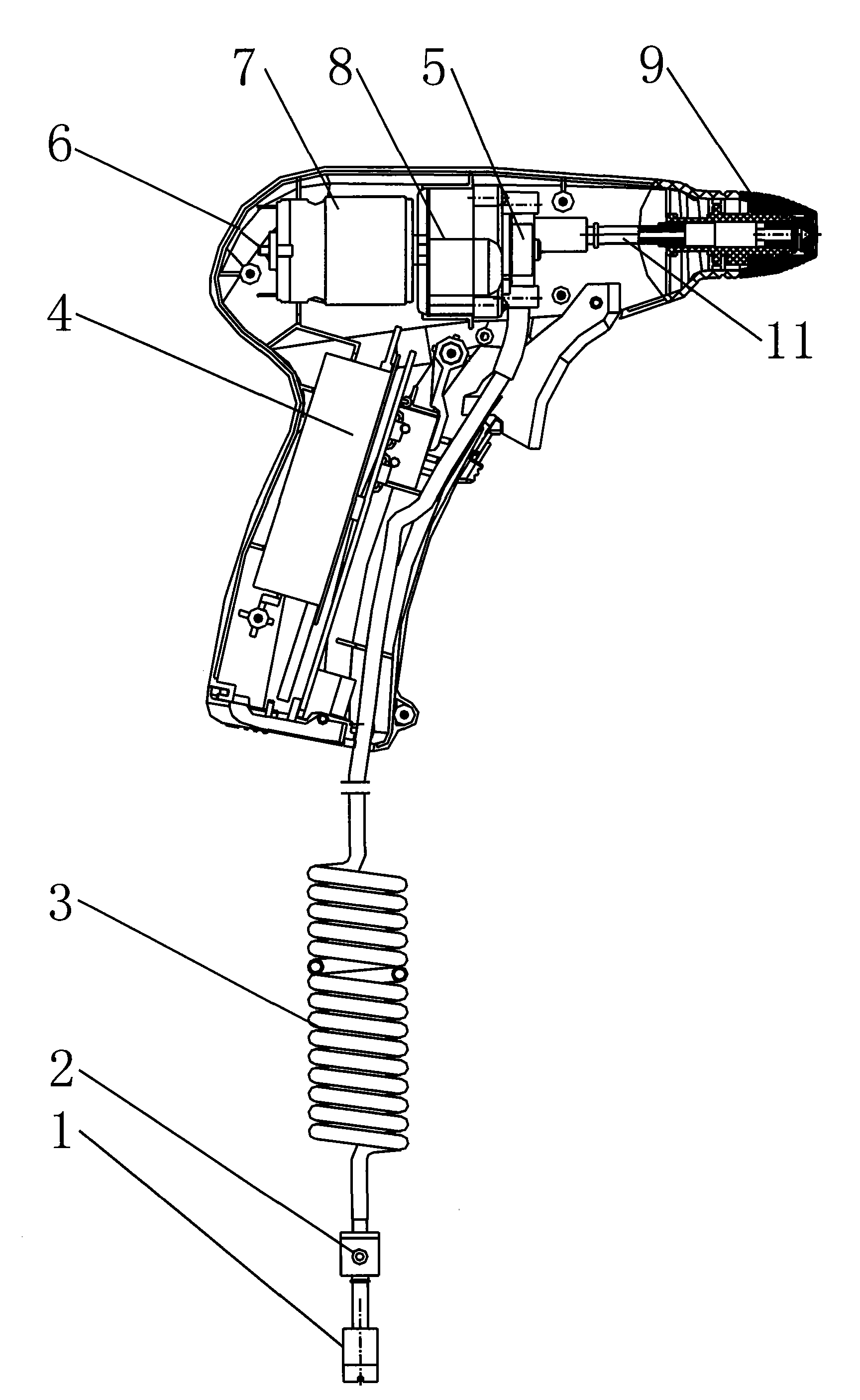
其中:1为过滤网装置;2为防漏件;3为进液管;4为锂电池装置;5为齿轮泵;6为枪体;7为电机;8为传动机构; Among them: 1 is the filter device; 2 is the anti-leakage part; 3 is the liquid inlet pipe; 4 is the lithium battery device; 5 is the gear pump; 6 is the gun body; 7 is the motor; 8 is the transmission mechanism;
9为旋盖喷嘴;91为套管;92为旋盖;93为套管密封圈;94为导流腔;95为喷嘴口;96为中空通道;97为喷嘴;98为通液孔;99为旋盖塞头;99-1为截流槽; 9 is a screw cap nozzle; 91 is a casing; 92 is a screw cap; 93 is a sleeve sealing ring; 94 is a diversion cavity; 95 is a nozzle opening; 96 is a hollow channel; 97 is a nozzle; 98 is a liquid hole; 99 is the screw cap plug; 99-1 is the intercepting groove;
10为加长旋盖喷嘴;101为导流腔;102为加长喷嘴密封圈;103为加长喷嘴;104为加长喷嘴芯;105为喷嘴口;106为通液孔; 10 is an extended screw cap nozzle; 101 is a diversion cavity; 102 is an extended nozzle sealing ring; 103 is an extended nozzle; 104 is an extended nozzle core; 105 is a nozzle opening; 106 is a liquid hole;
11为连接管。 11 is connecting pipe. the
具体实施方式Detailed ways
实施例:一种锂电电喷枪,如图1所示,包括枪体6、装于枪体6前端的旋盖喷嘴9,所述枪体6内设有锂电池装置4、由锂电池装置4驱动的电机7、齿轮泵5,所述电机7的输出轴带动齿轮泵5运转,所述枪体6的进液管3连接在齿轮泵5的进液口上,齿轮泵5的出液口通过连接管11与旋盖喷嘴9相连通,所述进液管3与外部储液装置相连。 Embodiment: a kind of lithium battery electric spray gun, as shown in Figure 1, comprises
所述电机7通过传动机构8带动齿轮泵5运转。所述进液管3为软管结构,进液管3下端装有防漏件2,所述防漏件2通过过滤网装置1将液体从外部储液装置吸入。 The
如图1所示,所述电喷枪按下开关按钮,启动锂电池装置4,电机7运行,带动传动机构8,传动机构8变速后经连动轴传至齿轮泵5,齿轮泵5运转,液体即由过滤网装置1吸入,经过防漏件2,通过进液管3,被齿轮泵5低压吸入,再由另一侧高压排出,排出的液体通过连接管11由旋盖喷嘴9中间的喷嘴小孔喷出。泵工作时喷口压力约为4~5公斤,喷出的水柱可达4~5米。 As shown in Figure 1, the electric spray gun presses the switch button, starts the
所述电喷枪的旋盖喷嘴9具有旋松及旋紧调节功能,即可在直线式喷射及喷雾式喷射两种模式之间转换。当旋盖旋松,旋盖喷嘴9与连接管11脱离形成低压状态,连接管11流出的液体直接就通过喷嘴射出,因此形成直线式喷射;当旋盖旋紧,旋盖喷嘴9与连接管11贴紧形成高压状态,连接管11流出的液体被压缩到高压后经喷嘴喷出,形成高压水雾喷雾式喷射。 The
如图6所示,所述旋盖喷嘴9也可以更换为加长旋盖喷嘴10,加长旋盖喷嘴10的后端通过螺纹接头安装在枪体6的前端,前端为可实现直线式喷射和喷雾式喷射两种喷射模式的旋盖喷嘴。 As shown in Figure 6, the
如图2至图5所示,所述旋盖喷嘴9包括通过螺纹连接在一起的套管91和旋盖92,所述套管91的内部设有后端开口的中空通道96,所述旋盖92前端的旋盖塞头99上设有喷嘴口95,所述套管91和和旋盖92之间设有套管密封圈93,所述套管密封圈93前部的套管91与喷嘴97组套和旋盖92之间形成导流腔94,所述套管91与喷嘴97组套内设有两个通液孔98,所述通液孔98将中空通道96与导流腔94连通在一起;所述旋盖塞头99的后端面上设有截流槽99-1,所述两个截流槽99-1位于旋盖塞头99后端相对的两侧,截流槽99-1从端面由外向内逐渐倾斜成螺旋型。所述套管91与喷嘴97组套旋至其前端与旋盖塞头99的后端面脱离时,旋盖塞头99的喷嘴口95喷出的液体呈喷直线,所述套管91与喷嘴97组套旋至其前端抵在旋盖塞头99的后端面上时,旋盖塞头99的喷嘴口95喷出的液体呈喷雾状。 As shown in Figures 2 to 5, the
所述套管91与喷嘴97组套的前部截面积小于后部截面积,前部和后部连接处为一台阶,所述前部的外圆周壁上设有一圈卡槽,所述密封圈93卡设在卡槽中;所述旋盖92内部设有前部截面积小后部截面积大的台阶孔,所述套管密封圈93与内孔壁前端之间为过盈配合,所述旋盖92的内孔壁后部、套管91的后部外周壁设有相互配合的螺纹。 The cross-sectional area of the front part of the
使用过程中,使用者用手旋动旋盖92,使旋盖92的内壁前端与套管91与喷嘴97组套的前端面分开并间隔一定距离时,如图3所示,水经过套管91与喷嘴97组套的中空通道96、通液孔98、导流腔94直接通过旋盖塞头99的喷嘴口95射出直线水形,此时可换喷嘴9处于直线式喷射状态。使用者用手旋动旋盖92,使旋盖92的内壁前端与套管91与喷嘴97组套前端面靠紧时,如图2所示,水经过套管91与喷嘴97组套的中空通道96、通液孔 98、导流腔94,再经过旋盖塞头99后端对称分布的两个截流槽99-1雾化后,最后通过旋盖塞头99的喷嘴口95喷出均匀的圆锥伞面水形,此时可换喷嘴9处于喷雾式喷射状态。 During use, the user rotates the
如图6至图8所示加长旋盖喷嘴结构,所述加长旋盖喷嘴10包括通过螺纹连接在一起的加长喷嘴103和加长喷嘴芯104,所述加长喷嘴芯104的内部设有后端开口的中空通道,所述加长喷嘴103的前端设有喷嘴口105,所述加长喷嘴芯104和加长喷嘴103之间设有加长喷嘴密封圈102,所述加长喷嘴密封圈102前部的加长喷嘴芯104和加长喷嘴103之间形成导流腔101,所述加长喷嘴芯104上设有若干个通液孔106,所述通液孔106将中空通道与导流腔101连通在一起;所述加长喷嘴芯104的前端面上设有截流槽,所述截流槽为相互平行的两个,两个截流槽位于加长喷嘴芯104前端相对的两侧,所述截流槽从端面由内向外逐渐加深,并在加长喷嘴芯104的外侧壁上形成有缺口。所述加长喷嘴芯104旋至其前端与加长喷嘴103的内壁前端脱离时,加长喷嘴103的喷嘴口105喷出的液体呈喷雾状,所述加长喷嘴芯104的前端抵在加长喷嘴103的内壁前端上时,加长喷嘴103的喷嘴口105喷出的液体呈直线状。 As shown in Figures 6 to 8, the structure of the extended
本实用新型操作实用简单,方便轻巧,具有自吸功能,吸程可达2mm,一次充放电,喷液可达10L;本实用新型的喷嘴具有旋松及旋紧调节功能,即可在直线式喷射及喷雾式喷射两种模式之间转换。 The utility model is practical and simple in operation, convenient and light, has a self-priming function, the suction distance can reach 2mm, and the spray liquid can reach 10L after one charge and discharge; Switch between two spray modes. the
以上仅是本实用新型的具体应用范例,对本实用新型的保护范围不构成任何限制。除上述实施例外,本实用新型还可以有其它实施方式。凡采用等同替换或等效变换形成的技术方案,均落在本实用新型所要求保护的范围之内。 The above are only specific application examples of the utility model, and do not constitute any limitation to the protection scope of the utility model. In addition to the above-mentioned embodiments, the utility model can also have other implementations. All technical solutions formed by equivalent replacement or equivalent transformation fall within the protection scope of the utility model. the
Claims (6)
Priority Applications (1)
| Application Number | Priority Date | Filing Date | Title |
|---|---|---|---|
| CN2010205550077U CN201848345U (en) | 2010-10-11 | 2010-10-11 | Lithium electric spray gun |
Applications Claiming Priority (1)
| Application Number | Priority Date | Filing Date | Title |
|---|---|---|---|
| CN2010205550077U CN201848345U (en) | 2010-10-11 | 2010-10-11 | Lithium electric spray gun |
Publications (1)
| Publication Number | Publication Date |
|---|---|
| CN201848345U true CN201848345U (en) | 2011-06-01 |
Family
ID=44090759
Family Applications (1)
| Application Number | Title | Priority Date | Filing Date |
|---|---|---|---|
| CN2010205550077U Expired - Fee Related CN201848345U (en) | 2010-10-11 | 2010-10-11 | Lithium electric spray gun |
Country Status (1)
| Country | Link |
|---|---|
| CN (1) | CN201848345U (en) |
Cited By (2)
| Publication number | Priority date | Publication date | Assignee | Title |
|---|---|---|---|---|
| CN105706757A (en) * | 2014-12-03 | 2016-06-29 | 宜昌益烟机械设备有限公司 | Electronic spray gun for accurate chemical spray |
| CN113786937A (en) * | 2021-09-27 | 2021-12-14 | 厦门英仕卫浴有限公司 | Convenient adjustable spray gun shower head |
-
2010
- 2010-10-11 CN CN2010205550077U patent/CN201848345U/en not_active Expired - Fee Related
Cited By (2)
| Publication number | Priority date | Publication date | Assignee | Title |
|---|---|---|---|---|
| CN105706757A (en) * | 2014-12-03 | 2016-06-29 | 宜昌益烟机械设备有限公司 | Electronic spray gun for accurate chemical spray |
| CN113786937A (en) * | 2021-09-27 | 2021-12-14 | 厦门英仕卫浴有限公司 | Convenient adjustable spray gun shower head |
Similar Documents
| Publication | Publication Date | Title |
|---|---|---|
| CN207308159U (en) | Liquid atomization device | |
| CN208942883U (en) | It is a kind of to facilitate the mouth sprays bottle for spraying medicament to the greatest extent | |
| CN201848345U (en) | Lithium electric spray gun | |
| CN203268010U (en) | Portable car cleaning machine | |
| CN107472685B (en) | Pressurizing device applied to liquid atomizer and liquid atomizer | |
| CN201807487U (en) | Novel hand micro sprayer | |
| CN207226017U (en) | Pressurizing device applied to liquid atomizer and liquid atomizer | |
| CN216862337U (en) | Plastic pistol pump | |
| CN216396752U (en) | Airless high-pressure spray gun | |
| CN204544540U (en) | High pressure airless sprayer | |
| CN202597280U (en) | Detachable jet pump sand suction device | |
| CN110448752B (en) | Pulse flusher | |
| CN212232818U (en) | A farmland irrigation spray device | |
| CN207107334U (en) | A sprayer for concentrated liquid spraying | |
| CN204842020U (en) | Electric nebulizer shower nozzle | |
| CN2899956Y (en) | A portable sprayer | |
| CN207948689U (en) | high-efficiency dual-purpose sprayer | |
| CN218573957U (en) | An electric sprayer energy-saving spraying device | |
| CN223717479U (en) | Spray pen cleaning machine | |
| CN208527054U (en) | A formaldehyde-removing spray gun with convenient replacement of nozzles | |
| CN112999063A (en) | Portable self-suction type electric nasal cavity irrigator | |
| CN216063837U (en) | Cleaning machine | |
| CN220735544U (en) | Oral cavity cleaning device for dysphagia patient | |
| CN206223497U (en) | A kind of portable gas sampler | |
| CN223221756U (en) | An electric plunger pump cleaning sprayer |
Legal Events
| Date | Code | Title | Description |
|---|---|---|---|
| C14 | Grant of patent or utility model | ||
| GR01 | Patent grant | ||
| C17 | Cessation of patent right | ||
| CF01 | Termination of patent right due to non-payment of annual fee |
Granted publication date: 20110601 Termination date: 20131011 |