CN201848323U - Encapsulating cover for dialyzer - Google Patents
Encapsulating cover for dialyzer Download PDFInfo
- Publication number
- CN201848323U CN201848323U CN2010205540770U CN201020554077U CN201848323U CN 201848323 U CN201848323 U CN 201848323U CN 2010205540770 U CN2010205540770 U CN 2010205540770U CN 201020554077 U CN201020554077 U CN 201020554077U CN 201848323 U CN201848323 U CN 201848323U
- Authority
- CN
- China
- Prior art keywords
- bulge loop
- lid
- dialyzer
- encapsulating
- rib
- Prior art date
- Legal status (The legal status is an assumption and is not a legal conclusion. Google has not performed a legal analysis and makes no representation as to the accuracy of the status listed.)
- Expired - Fee Related
Links
- 239000000758 substrate Substances 0.000 claims abstract description 27
- 230000000295 complement effect Effects 0.000 claims description 5
- 230000008878 coupling Effects 0.000 claims description 4
- 238000010168 coupling process Methods 0.000 claims description 4
- 238000005859 coupling reaction Methods 0.000 claims description 4
- 230000000694 effects Effects 0.000 abstract description 13
- 239000003292 glue Substances 0.000 abstract description 6
- 230000001105 regulatory effect Effects 0.000 description 6
- 239000000084 colloidal system Substances 0.000 description 4
- 239000008280 blood Substances 0.000 description 2
- 210000004369 blood Anatomy 0.000 description 2
- 230000007812 deficiency Effects 0.000 description 2
- 238000004519 manufacturing process Methods 0.000 description 2
- 238000000034 method Methods 0.000 description 2
- 238000010586 diagram Methods 0.000 description 1
- 238000005538 encapsulation Methods 0.000 description 1
- 238000005516 engineering process Methods 0.000 description 1
- 239000000835 fiber Substances 0.000 description 1
- 238000001631 haemodialysis Methods 0.000 description 1
- 238000007689 inspection Methods 0.000 description 1
- 210000003734 kidney Anatomy 0.000 description 1
- 238000002360 preparation method Methods 0.000 description 1
- 239000011435 rock Substances 0.000 description 1
Images
Landscapes
- External Artificial Organs (AREA)
Abstract
The utility model relates to an encapsulating cover for dialyzer, which comprises a cover body and a ring body matched with each other, wherein a substrate and a block raised ring are arranged on the cover body; the raised ring is arranged on the substrate and is fixedly connected to the substrate; the ring body is provided with a buckle ring fastened with the shell of the dialyzer and an inlay slot matched with the block raised ring; the buckle ring and the inlay slot are arranged at two sides of the ring body; the block raised ring is matched with the inlay slot; the cover body is provided with an adjustable raised ring; the adjustable raised ring is fixedly connected to the substrate; the outer wall of the adjustable raised ring is fixedly connected to the inner wall of the block raised ring; the height of the adjustable raised ring is less than the height of the block raised ring; the cover body is provided with a rib strip; the rib strip and the block raised ring are arranged at the same side of the cover body; and the rib strip is fixedly connected to the cover body. Through the encapsulating cover for dialyzer, the block raised ring of the cover body is inserted into the inlay slot on the ring body, so the distance between the cover body and the ring body is shortened, the glue dosage is saved and the centrifugal effect is increased.
Description
Technical field
The utility model relates to the dialyzer field, particularly relates to a kind of dialyzer encapsulating lid.
Background technology
Dialyzer is commonly called as artificial kidney, has obtained extensive use clinically.By carrying out haemodialysis, life-span that can the proper extension patient.Dialyzer generally includes housing, is arranged at hollow fibre, the blood feed tube that is arranged at the housing two ends, blood drain pipe, dislysate drain pipe and dislysate feed tube in the housing.Dialyzer is in preparation process, and the housing of tunica fibrosa need being packed on inspection, encapsulating, by the two ends encapsulation of two encapsulatings lids with housing, passes through steps such as centrifugal treating then again.The centrifugal treating step can be so that colloid be uniformly distributed in the tunica fibrosa in the dialyzer housing.The encapsulating lid at dialyzer housing two ends directly influences processing cost and centrifugal effect.
The encapsulating that uses in prior art lid, it is with after dialyzer housing two ends cooperate, and more glue need be wasted during the one side encapsulating in the bigger space of existence between the tunica fibrosa in the dialyzer housing and the encapsulating lid, makes the production cost increase.In addition, in the centrifugal treating process, effective exposure level of the encapsulating at tunica fibrosa and dialyzer housing two ends lid directly influences centrifugal effect, when tunica fibrosa and dialyzer housing two end in contact are unreal, cause rocking of tunica fibrosa in the centrifugal treating process easily, influence the performance of product.
Therefore, at the prior art deficiency, provide a kind of dialyzer encapsulating lid very necessary to overcome the prior art weak point.
Summary of the invention
The purpose of this utility model is to avoid the deficiencies in the prior art part and a kind of dialyzer encapsulating lid is provided, and uses this dialyzer encapsulating lid can save the glue amount, and has centrifugal preferably effect.
The purpose of this utility model realizes by following technical measures.
A kind of dialyzer encapsulating covers, and is provided with the lid and the circle body of mutual coupling;
Described lid is provided with substrate and snaps in bulge loop, and the described bulge loop that snaps in is arranged at described substrate and fixedlys connected with described substrate;
Described circle body is provided with and is used for the button bit ring of the housing snapping of dialyzer and is used for snapping in the embedding groove that bulge loop cooperates with described, and described button bit ring is arranged at the relative both sides of described circle body with described embedding groove;
Describedly snap in bulge loop and described embedding groove is complementary.
Above-mentioned lid is provided with the adjusting bulge loop, and described adjusting bulge loop is fixedlyed connected with described substrate, and the outside wall surface of described adjusting bulge loop is fixedlyed connected with the described internal face that snaps in bulge loop, and the height of described adjusting bulge loop is less than the described height that snaps in bulge loop.
It is above-mentioned that to snap in that bulge loop is set to highly be 0.3---0.6cm snaps in bulge loop.
It highly is 0.05 that above-mentioned adjusting bulge loop is set to---the adjusting bulge loop of 0.3cm.
Above-mentioned lid is provided with rib, described rib and describedly snap in the homonymy that bulge loop is positioned at described lid, and described rib is fixedlyed connected with described lid.
Above-mentioned rib is set to two or more, and described rib is uniformly distributed in described lid.
Preferably, above-mentioned rib is set to 4 to 10.
Preferred, above-mentioned rib is set to 6.
Above-mentioned rib is set to cuboid, square or cylinder.
Above-mentionedly snap in bulge loop and described substrate is set to integrated formed structure; Described rib and described substrate are set to integrated formed structure.
A kind of dialyzer encapsulating that the utility model provides covers, and is provided with the lid and the circle body of mutual coupling; Described lid is provided with substrate and snaps in bulge loop, and described bulge loop is arranged at described substrate and fixedlys connected with described substrate; Described circle body is provided with and is used for the button bit ring of the housing snapping of dialyzer and is used for snapping in the embedding groove that bulge loop cooperates with described, and described button bit ring is arranged at the relative both sides of described circle body with described embedding groove; Describedly snap in bulge loop and described embedding groove is complementary.The embedding groove that bulge loop by lid snaps in circle body cooperates, and can shorten the distance between lid and the circle body, makes this dialyzer encapsulating lid with after the dialyzer housing cooperates, and the tunica fibrosa two ends of dialyzer inside can be stamped effect with encapsulating and be contacted.Can save the glue amount, improve centrifugal effect.
Description of drawings
Utilize accompanying drawing that the utility model is further described, but the content in the accompanying drawing does not constitute any restriction of the present utility model.
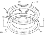
Fig. 1 is the schematic diagram of a kind of dialyzer encapsulating lid of the present utility model.
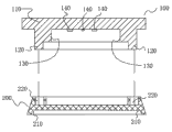
Fig. 2 is Fig. 1 " A-A " cutaway view.
In Fig. 1 and Fig. 2, comprising:
Regulate bulge loop 130, rib 140,
The specific embodiment
The utility model is described in further detail with the following Examples.
A kind of dialyzer encapsulating lid as shown in Figure 1 and Figure 2, is provided with the lid 100 and the circle body 200 of mutual coupling.
It is corresponding with the position of embedding groove 220 to snap in bulge loop 120, and size is complementary.
During use, circle body 200 by button bit ring 210 and dialyzer housing snapping, and then with the embedding groove 220 that bulge loop 120 snaps in circle body 200 that snaps in of lid 100, is made to be connected between lid 100 and the circle body 200.By snapping in cooperating of bulge loop 120 and embedding groove 220, this assembling mode can shorten the distance between lid 100 and the circle body 200, makes this encapsulating lid with after the dialyzer housing cooperates, and the tunica fibrosa two ends of dialyzer inside can be stamped effect with encapsulating and be contacted.Thereby can save the glue amount when encapsulating, when centrifugal treating, because tunica fibrosa can effectively contact with the encapsulating lid, tunica fibrosa rocks in the dialyzer housing in the time of therefore can avoiding centrifugal treating, so centrifugal effect is better simultaneously.
Because the embedding groove 220 that snaps in bulge loop 120 and circle body 200 of lid 100 is complementary, the adjusting bulge loop 130 of fixedlying connected with the internal face that snaps in bulge loop 120 is when assembling, can prop up the groove eaves of embedding groove 220, thereby realize regulating the effect of distance between lid 100 and the circle body 200.
The height that snaps in bulge loop 120 is set to 0.3 usually---0.6cm, and the height of regulating bulge loop 130 is set to 0.05 usually---and 0.3cm, certainly, precondition is that the at first satisfied height of bulge loop 120 that snaps in is greater than the height of regulating bulge loop 130.
Dialyzer encapsulating of the present utility model lid during use, with the button bit ring 210 and the dialyzer housing snapping of circle body 200, and then with the embedding groove 220 that bulge loop 120 snaps in circle body 200 that snaps in of lid 100, makes to be connected between lid 100 and the circle body 200.By snapping in cooperating of bulge loop 120 and embedding groove 220, this assembling mode can shorten the distance between lid 100 and the circle body 200, makes this encapsulating lid with after the dialyzer housing cooperates, and the tunica fibrosa two ends of dialyzer inside can be stamped effect with encapsulating and be contacted.Thereby when encapsulating, can save the glue amount, save production cost.The rib 140 that lid 100 is provided with, make encapsulating lid with after the dialyzer housing cooperates, prop up the tunica fibrosa of dialyzer enclosure interior by rib 140, prevent that tunica fibrosa from moving when centrifugal treating, colloid was mobile when the slit between rib 140 and the rib 140 helped centrifugal treating simultaneously, thereby reached centrifugal preferably effect.
Should be noted that at last; above embodiment is only in order to the explanation the technical solution of the utility model but not to the restriction of the utility model protection domain; although the utility model has been done detailed description with reference to preferred embodiment; those of ordinary skill in the art is to be understood that; can make amendment or be equal to replacement the technical solution of the utility model, and not break away from the essence and the scope of technical solutions of the utility model.
Claims (10)
1. a dialyzer encapsulating lid is characterized in that: the lid and the circle body that are provided with mutual coupling;
Described lid is provided with substrate and snaps in bulge loop, and the described bulge loop that snaps in is arranged at described substrate and fixedlys connected with described substrate;
Described circle body is provided with and is used for the button bit ring of the housing snapping of dialyzer and is used for snapping in the embedding groove that bulge loop cooperates with described, and described button bit ring is arranged at the relative both sides of described circle body with described embedding groove;
Describedly snap in bulge loop and described embedding groove is complementary.
2. according to the described dialyzer encapsulating lid of claim 1, it is characterized in that: described lid is provided with the adjusting bulge loop, described adjusting bulge loop is fixedlyed connected with described substrate, the outside wall surface of described adjusting bulge loop is fixedlyed connected with the described internal face that snaps in bulge loop, and the height of described adjusting bulge loop is less than the described height that snaps in bulge loop.
3. dialyzer encapsulating according to claim 2 lid is characterized in that: described to snap in that bulge loop is set to highly be 0.3---0.6cm snaps in bulge loop.
4. dialyzer encapsulating lid according to claim 2, it is characterized in that: it highly is 0.05 that described adjusting bulge loop is set to---the adjusting bulge loop of 0.3cm.
5. according to any described dialyzer encapsulating lid of claim 1 to 4, it is characterized in that: described lid is provided with rib, described rib and describedly snap in the homonymy that bulge loop is positioned at described lid, and described rib is fixedlyed connected with described lid.
6. dialyzer encapsulating lid according to claim 5, it is characterized in that: described rib is set to two or more, and described rib is uniformly distributed in described lid.
7. dialyzer encapsulating lid according to claim 6, it is characterized in that: described rib is set to 4 to 10.
8. dialyzer encapsulating lid according to claim 7, it is characterized in that: described rib is set to 6.
9. dialyzer encapsulating lid according to claim 8, it is characterized in that: described rib is set to cuboid, square or cylinder.
10. dialyzer encapsulating according to claim 9 lid is characterized in that: describedly snap in bulge loop and described substrate is set to integrated formed structure; Described rib and described substrate are set to integrated formed structure.
Priority Applications (1)
| Application Number | Priority Date | Filing Date | Title |
|---|---|---|---|
| CN2010205540770U CN201848323U (en) | 2010-10-09 | 2010-10-09 | Encapsulating cover for dialyzer |
Applications Claiming Priority (1)
| Application Number | Priority Date | Filing Date | Title |
|---|---|---|---|
| CN2010205540770U CN201848323U (en) | 2010-10-09 | 2010-10-09 | Encapsulating cover for dialyzer |
Publications (1)
| Publication Number | Publication Date |
|---|---|
| CN201848323U true CN201848323U (en) | 2011-06-01 |
Family
ID=44090737
Family Applications (1)
| Application Number | Title | Priority Date | Filing Date |
|---|---|---|---|
| CN2010205540770U Expired - Fee Related CN201848323U (en) | 2010-10-09 | 2010-10-09 | Encapsulating cover for dialyzer |
Country Status (1)
| Country | Link |
|---|---|
| CN (1) | CN201848323U (en) |
Cited By (1)
| Publication number | Priority date | Publication date | Assignee | Title |
|---|---|---|---|---|
| CN106166310A (en) * | 2016-08-25 | 2016-11-30 | 迈得医疗工业设备股份有限公司 | Dialyser injecting glue lid apparatus for removing |
-
2010
- 2010-10-09 CN CN2010205540770U patent/CN201848323U/en not_active Expired - Fee Related
Cited By (1)
| Publication number | Priority date | Publication date | Assignee | Title |
|---|---|---|---|---|
| CN106166310A (en) * | 2016-08-25 | 2016-11-30 | 迈得医疗工业设备股份有限公司 | Dialyser injecting glue lid apparatus for removing |
Similar Documents
| Publication | Publication Date | Title |
|---|---|---|
| CN207038571U (en) | secondary battery | |
| CN103000617B (en) | Semiconductor package and its manufacturing method | |
| CN209298181U (en) | Button Battery | |
| CN107404034A (en) | Electric connector | |
| CN201848323U (en) | Encapsulating cover for dialyzer | |
| TR201810671T4 (en) | Waterproof apparatus and terminal for terminal side button. | |
| JP6381651B2 (en) | Waterproof plug for mobile devices | |
| CN208706991U (en) | Double waterproof sealing structure applied to connectors | |
| TWM556033U (en) | Waterproof connector | |
| CN211265527U (en) | a button battery | |
| US20250177618A1 (en) | Breast pump | |
| CN206117959U (en) | Earphone seat and have its mobile terminal | |
| CN205993042U (en) | The casing assembly of mobile terminal and mobile terminal | |
| CN209804632U (en) | Triode with dampproofing structure | |
| CN207528789U (en) | Waterproof structure of a smart meter | |
| CN106921768A (en) | Mobile terminal waterproof construction and mobile terminal | |
| CN201717922U (en) | Portable terminal device | |
| MY150794A (en) | Reusable miniaturized reference electrode | |
| CN107196111A (en) | Connector and manufacturing method thereof | |
| CN202565625U (en) | High-protective anti-interference PLC outer shell | |
| WO2018094941A1 (en) | Connector interface and mobile terminal | |
| CN201715927U (en) | Sealing structure of miniature structure | |
| CN205507840U (en) | USB flash disk with type -c3. 0 interface | |
| CN203971006U (en) | A kind of encapsulating cover for dialyzer | |
| CN206211141U (en) | Connector and mobile terminal |
Legal Events
| Date | Code | Title | Description |
|---|---|---|---|
| C14 | Grant of patent or utility model | ||
| GR01 | Patent grant | ||
| CF01 | Termination of patent right due to non-payment of annual fee |
Granted publication date: 20110601 Termination date: 20161009 |
|
| CF01 | Termination of patent right due to non-payment of annual fee |