CN201848157U - Arrangement structure for gas distributing pipeline of multi-medium filtering station - Google Patents
Arrangement structure for gas distributing pipeline of multi-medium filtering station Download PDFInfo
- Publication number
- CN201848157U CN201848157U CN2010205158061U CN201020515806U CN201848157U CN 201848157 U CN201848157 U CN 201848157U CN 2010205158061 U CN2010205158061 U CN 2010205158061U CN 201020515806 U CN201020515806 U CN 201020515806U CN 201848157 U CN201848157 U CN 201848157U
- Authority
- CN
- China
- Prior art keywords
- valve
- pipeline
- filter
- air
- source control
- Prior art date
- Legal status (The legal status is an assumption and is not a legal conclusion. Google has not performed a legal analysis and makes no representation as to the accuracy of the status listed.)
- Expired - Fee Related
Links
- 238000001914 filtration Methods 0.000 title 1
- 238000011001 backwashing Methods 0.000 abstract description 7
- XLYOFNOQVPJJNP-UHFFFAOYSA-N water Substances O XLYOFNOQVPJJNP-UHFFFAOYSA-N 0.000 abstract description 6
- 238000000034 method Methods 0.000 abstract description 4
- 239000000571 coke Substances 0.000 abstract 1
- 238000004939 coking Methods 0.000 abstract 1
- 238000005259 measurement Methods 0.000 abstract 1
- 238000010586 diagram Methods 0.000 description 3
- 230000000694 effects Effects 0.000 description 1
- 230000002708 enhancing effect Effects 0.000 description 1
- 239000000463 material Substances 0.000 description 1
Images


Classifications
-
- Y—GENERAL TAGGING OF NEW TECHNOLOGICAL DEVELOPMENTS; GENERAL TAGGING OF CROSS-SECTIONAL TECHNOLOGIES SPANNING OVER SEVERAL SECTIONS OF THE IPC; TECHNICAL SUBJECTS COVERED BY FORMER USPC CROSS-REFERENCE ART COLLECTIONS [XRACs] AND DIGESTS
- Y02—TECHNOLOGIES OR APPLICATIONS FOR MITIGATION OR ADAPTATION AGAINST CLIMATE CHANGE
- Y02W—CLIMATE CHANGE MITIGATION TECHNOLOGIES RELATED TO WASTEWATER TREATMENT OR WASTE MANAGEMENT
- Y02W10/00—Technologies for wastewater treatment
- Y02W10/10—Biological treatment of water, waste water, or sewage
Landscapes
- Filtering Of Dispersed Particles In Gases (AREA)
Abstract
多介质过滤站布气管道布置结构,属于水处理领域,它主要用于炼焦焦炉炉体膨胀状况的测量,它包括24台过滤器、循环泵及其管道,其特征是末端管道通过阀门与气源控制阀的输出管道连接,气源控制阀的输出管道上设有阀门,在第12个过滤器与第13个过滤器之间的管道上设有阀门。本实用新型由非循环管网改变为循环管网,通过调节阀门可控制水气流的流向和水气流量,保证反洗过程中水气流量均匀,避免反洗跑料现象。
The air distribution pipeline layout structure of the multi-media filter station belongs to the field of water treatment. It is mainly used for the measurement of the expansion of the coke oven body in coking. It includes 24 filters, circulating pumps and pipelines. The output pipeline of the air source control valve is connected, the output pipeline of the air source control valve is provided with a valve, and the pipeline between the 12th filter and the 13th filter is provided with a valve. The utility model is changed from a non-circulating pipe network to a circulating pipe network, and the flow direction and flow of water and air can be controlled by adjusting the valve, so as to ensure uniform water and air flow in the backwashing process and avoid the phenomenon of backwashing.
Description
技术领域technical field
本实用新型属于水处理领域。The utility model belongs to the field of water treatment.
背景技术Background technique
图1是现有多介质过滤站布气管道布置结构的示意图,它在运行中存在管网末端的压力始终低于反洗所要求的压力值,管网始端的压力始终超过要求的压力值,导致靠近管网始端的过滤器发生严重跑料现象,靠近管网末端的过滤器增加反洗时间。Figure 1 is a schematic diagram of the layout structure of the gas distribution pipeline of the existing multi-media filter station. During its operation, the pressure at the end of the pipe network is always lower than the pressure value required for backwashing, and the pressure at the beginning of the pipe network always exceeds the required pressure value. As a result, the filter near the beginning of the pipe network has a serious material running phenomenon, and the filter near the end of the pipe network increases the backwash time.
发明内容Contents of the invention
为了使过滤器在反洗过程中布气均匀,从而增强反洗效果,本实用新型提供一种多介质过滤站布气管道布置结构。In order to make the air distribution of the filter uniform during the backwashing process, thereby enhancing the backwashing effect, the utility model provides an air distribution pipeline arrangement structure of a multi-media filter station.
本实用新型包括24台过滤器、循环泵及其管道,其特征是末端管道通过阀门与气源控制阀的输出管道连接,气源控制阀的输出管道上设有阀门,在第12个过滤器与第13个过滤器之间的管道上设有阀门。The utility model includes 24 filters, circulating pumps and pipelines thereof, and is characterized in that the terminal pipeline is connected with the output pipeline of the gas source control valve through a valve, and the output pipeline of the gas source control valve is provided with a valve, and the twelfth filter There is a valve on the pipeline between the 13th filter.
本实用新型由非循环管网改变为循环管网,通过调节阀门可控制水气流的流向和水气流量,保证反洗过程中水气流量均匀,避免反洗跑料现象。The utility model is changed from a non-circulating pipe network to a circulating pipe network, and the flow direction and flow of water and air can be controlled by adjusting the valve, so as to ensure uniform water and air flow in the backwashing process and avoid the phenomenon of backwashing.
附图说明Description of drawings
图1是现有多介质过滤站布气管道布置结构的示意图。Fig. 1 is a schematic diagram of the layout structure of the air distribution pipeline of the existing multi-media filter station.
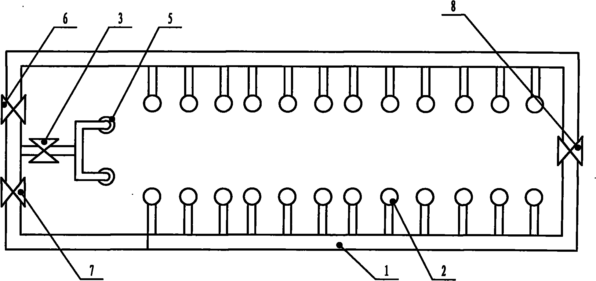
图2是本实用新型实施例的示意图。Fig. 2 is a schematic diagram of an embodiment of the utility model.
图中:1、管道,2、过滤器,3、阀门,5、循环泵,6、阀门,7、阀门,8、阀门,9、第12个过滤器,10、第13个过滤器,11、末端管道。In the figure: 1, pipeline, 2, filter, 3, valve, 5, circulating pump, 6, valve, 7, valve, 8, valve, 9, the 12th filter, 10, the 13th filter, 11 , End pipe.
具体实施方式Detailed ways
实施例:图2所示,本实施例包括24台过滤器、两台循环泵5及其管道1,两台循环泵5的输出管道上设有阀门3,其特征是末端管道11通过阀门7与气源控制阀的输出管道连接,气源控制阀的输出管道上设有阀门6,在第12个过滤器9与第13个过滤器10之间的管道上设有阀门8。Embodiment: as shown in Fig. 2, present embodiment comprises 24 filters, two circulating
Claims (1)
Priority Applications (1)
| Application Number | Priority Date | Filing Date | Title |
|---|---|---|---|
| CN2010205158061U CN201848157U (en) | 2010-08-31 | 2010-08-31 | Arrangement structure for gas distributing pipeline of multi-medium filtering station |
Applications Claiming Priority (1)
| Application Number | Priority Date | Filing Date | Title |
|---|---|---|---|
| CN2010205158061U CN201848157U (en) | 2010-08-31 | 2010-08-31 | Arrangement structure for gas distributing pipeline of multi-medium filtering station |
Publications (1)
| Publication Number | Publication Date |
|---|---|
| CN201848157U true CN201848157U (en) | 2011-06-01 |
Family
ID=44090572
Family Applications (1)
| Application Number | Title | Priority Date | Filing Date |
|---|---|---|---|
| CN2010205158061U Expired - Fee Related CN201848157U (en) | 2010-08-31 | 2010-08-31 | Arrangement structure for gas distributing pipeline of multi-medium filtering station |
Country Status (1)
| Country | Link |
|---|---|
| CN (1) | CN201848157U (en) |
-
2010
- 2010-08-31 CN CN2010205158061U patent/CN201848157U/en not_active Expired - Fee Related
Similar Documents
| Publication | Publication Date | Title |
|---|---|---|
| CN202105506U (en) | Power oil processor | |
| CN203782123U (en) | Electric oil treatment box | |
| CN203090598U (en) | Filter device | |
| CN201848157U (en) | Arrangement structure for gas distributing pipeline of multi-medium filtering station | |
| CN202700904U (en) | Interior rapid cleaning device of flowmeter | |
| CN204454852U (en) | Point cancellation element owed by a kind of TFT glass platinum | |
| CN204550461U (en) | A kind of coke oven heating blast furnace gas air feeder | |
| CN204933031U (en) | A kind of multiplex strainer valve | |
| CN203848711U (en) | Flexibly adjusted cool water tower device | |
| CN202613048U (en) | Gas transmission system for natural gas pipeline | |
| CN202002548U (en) | Circulating water cooler with backwashing function | |
| CN203240160U (en) | Flange plate with temperature control function | |
| CN205173102U (en) | Dual -purpose type valve island of aqueous vapor | |
| CN202597991U (en) | Equal-pressure distribution pipe | |
| CN205264443U (en) | Electric furnace transformer with oil water chiller | |
| CN202672243U (en) | Box type booster water supply device with efficient water distributor | |
| CN204554105U (en) | A kind of fuel oil conveyance conduit | |
| CN201982967U (en) | Catalytic assistant filling device for natural gas | |
| CN203389444U (en) | Air drying and filtering system | |
| CN203023802U (en) | Pressure regulating tank for slurry pipeline | |
| CN203880167U (en) | Fuel gas pressure regulator with filtering device | |
| CN202629245U (en) | Sluice valve body | |
| CN201926370U (en) | Circulated-water cooler with automatic back-flushing function | |
| CN202105605U (en) | Gas blending device for blending tank | |
| CN204530851U (en) | Well pressurization system |
Legal Events
| Date | Code | Title | Description |
|---|---|---|---|
| C14 | Grant of patent or utility model | ||
| GR01 | Patent grant | ||
| CF01 | Termination of patent right due to non-payment of annual fee | ||
| CF01 | Termination of patent right due to non-payment of annual fee |
Granted publication date: 20110601 Termination date: 20170831 |