CN201848120U - Automatic drainage device of coalescing separator - Google Patents
Automatic drainage device of coalescing separator Download PDFInfo
- Publication number
- CN201848120U CN201848120U CN2010205579200U CN201020557920U CN201848120U CN 201848120 U CN201848120 U CN 201848120U CN 2010205579200 U CN2010205579200 U CN 2010205579200U CN 201020557920 U CN201020557920 U CN 201020557920U CN 201848120 U CN201848120 U CN 201848120U
- Authority
- CN
- China
- Prior art keywords
- sewage
- liquid level
- oil groove
- valve
- oil
- Prior art date
- Legal status (The legal status is an assumption and is not a legal conclusion. Google has not performed a legal analysis and makes no representation as to the accuracy of the status listed.)
- Expired - Fee Related
Links
- 239000010865 sewage Substances 0.000 claims abstract description 58
- 239000007788 liquid Substances 0.000 claims abstract description 28
- 230000001939 inductive effect Effects 0.000 claims description 15
- 210000002421 cell wall Anatomy 0.000 claims description 3
- XLYOFNOQVPJJNP-UHFFFAOYSA-N water Substances O XLYOFNOQVPJJNP-UHFFFAOYSA-N 0.000 abstract description 5
- 238000000926 separation method Methods 0.000 description 5
- 238000005516 engineering process Methods 0.000 description 3
- 239000002351 wastewater Substances 0.000 description 3
- 239000004519 grease Substances 0.000 description 1
- 239000003595 mist Substances 0.000 description 1
- 238000005086 pumping Methods 0.000 description 1
Images

Landscapes
- Control Of Non-Electrical Variables (AREA)
Abstract
The utility model discloses an automatic drainage device of a coalescing separator. The drainage device comprises a sewage or oil groove, wherein the sewage or oil groove is provided with a blow-off valve. The automatic drainage device is characterized in that: the sewage and oil groove is provided with a control device for opening or closing the blow-off valve; the control device comprises a liquid level sensor; the liquid level sensor comprises an upper liquid level sensing switch and a lower liquid level sensing switch which are arranged on the upper part and the lower part of the groove wall of the sewage or oil groove respectively; the blow-off valve is an electromagnetic valve; and the upper liquid level sensing switch and the lower liquid level sensing switch are connected with the electromagnetic valve. The liquid level of sewage in the sewage or oil groove is set, so that the valve opening time and the valve closing time of the electromagnetic valve are controlled, the amount of the sewage in the sewage or oil groove is prevented from exceeding standard, oil and water can be separated from each other normally, and the quality of an oil product is ensured.
Description
Technical field
The utility model relates to a kind of improvement invention of coalescing separator, particularly be a kind of improvement invention of automatic draining device of coalescing separator.
Background technology
Coalescing separator is mainly used in the solution-air separation or liquid-liquid separates, and it contains two kinds of filter cores, that is: gather filter core and separate filter core, can select the form of one or both cartridge combination to carry out work during practical operation.Such as in the solution-air coalescing separator, contain small-amount free shape liquid (sewage or mist of oil), gas through behind the coalescing separator, liquid coarse separation in the gas can be come out and focuses in sewage or the oil groove, when the water in sewage or the oil groove reaches a certain amount of, the staff opens sewage draining valve, and sewage is discharged; Clean gas then flows out from the outlet of coalescing separator.Overstock too much for fear of sewage, the staff must check sewage quantity and sewage effluent often.Artificial supervision and sewage effluent not only bring many inconvenience to work, and easily make mistakes, and quantity of wastewater effluent is grasped bad, make sewage overstock, and finally can cause sewage fully not separate from gas, make gaseous mass reduce.Equally, liquid-liquid coarse separation is mainly used in the occasion of oil dehydrating or deoiling of wastewater, and oil dehydrating mainly is after the moisture in the oil product is come out through coarse separation and focuses in sewage or the oil; And deoiling of wastewater mainly is to focus in sewage or the oil groove after a spot of grease in the water is broken away from.
Summary of the invention
In view of the existing technical problem of background technology, technical problem to be solved in the utility model provides the automatic draining device of the coalescing separator of the automatic sewage effluent of a kind of energy.
In order to solve the problems of the technologies described above, the utility model is to adopt following scheme to realize: the automatic draining device of this kind coalescing separator, include sewage or oil groove, described sewage or oil groove are provided with sewage draining valve, it is characterized in that described sewage or oil groove are provided with opens or closed control device this sewage draining valve, described this control device includes level sensor, described level sensor includes liquid level inductive switch and following liquid level inductive switch, on described, following liquid level inductive switch is separately positioned on the upper and lower of sewage or oil groove cell wall, described sewage draining valve is a magnetic valve, described on, following liquid level inductive switch all connects with magnetic valve.
The utility model connects upper and lower liquid level inductive switch with magnetic valve, by setting the liquid level of sewage in sewage or the oil groove, the time that control magnetic valve valve is driven valve and closed valve, when the sewage in sewage or the oil groove reaches the liquid level of setting, level sensor passes to magnetic valve with instruction, the order magnetic valve is opened valve, carries out blowdown; When sewage quantity dropped to safety index, magnetic valve is automatic-closing valve then, guaranteed that so the sewage quantity in sewage or the oil groove can not exceed standard, and made oil, water normal separation, guaranteed oil quality.
Description of drawings
Further describe relevant details of the present utility model below in conjunction with accompanying drawing.
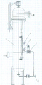
Fig. 1 is a structural representation of the present utility model.
Fig. 2 is the structural representation of coalescing separator.
The specific embodiment
With reference to Fig. 1, the pumping equipment of this kind coalescing separator, include sewage or oil groove 2, described sewage or oil groove 2 are provided with sewage draining valve 3, described sewage or oil groove 2 are provided with this sewage draining valve 3 are opened or closed control device, described this control device includes level sensor 1, described level sensor includes liquid level inductive switch 4 and following liquid level inductive switch 5, on described, following liquid level inductive switch 4,5 are separately positioned on the upper and lower of sewage or oil groove 2 cell walls, described sewage draining valve 3 is a magnetic valve, described on, following liquid level inductive switch 4,5 all connect with magnetic valve 3.
With reference to Fig. 2, described coalescing separator 6 is separated the sewage in the oil product, and stores in sewage or the oil groove 2, when the water level in sewage or the oil groove 2 reaches the value of setting, last liquid level inductive switch 4 sends instruction to magnetic valve 3 with this information, makes its Open valve, and sewage is discharged from sewage draining exit 7; When sewage dropped to the position of setting, following liquid level inductive switch 5 sent instruction, makes magnetic valve 3 valve closings, stops blowdown, so, guaranteed that the sewage in sewage or the oil groove 2 is controlled in the safe boundary.
Claims (1)
1. the automatic draining device of a coalescing separator, include sewage or oil groove (2), described sewage or oil groove (2) are provided with sewage draining valve (3), it is characterized in that described sewage or oil groove (2) are provided with opens or closed control device this sewage draining valve (3), described this control device includes level sensor (1), described level sensor includes liquid level inductive switch (4) and following liquid level inductive switch (5), on described, following liquid level inductive switch (4,5) be separately positioned on the upper and lower of sewage or oil groove (2) cell wall, described sewage draining valve (3) is a magnetic valve, on described, following liquid level inductive switch (4,5) all connects with magnetic valve.
Priority Applications (1)
| Application Number | Priority Date | Filing Date | Title |
|---|---|---|---|
| CN2010205579200U CN201848120U (en) | 2011-01-25 | 2011-01-25 | Automatic drainage device of coalescing separator |
Applications Claiming Priority (1)
| Application Number | Priority Date | Filing Date | Title |
|---|---|---|---|
| CN2010205579200U CN201848120U (en) | 2011-01-25 | 2011-01-25 | Automatic drainage device of coalescing separator |
Publications (1)
| Publication Number | Publication Date |
|---|---|
| CN201848120U true CN201848120U (en) | 2011-06-01 |
Family
ID=44090535
Family Applications (1)
| Application Number | Title | Priority Date | Filing Date |
|---|---|---|---|
| CN2010205579200U Expired - Fee Related CN201848120U (en) | 2011-01-25 | 2011-01-25 | Automatic drainage device of coalescing separator |
Country Status (1)
| Country | Link |
|---|---|
| CN (1) | CN201848120U (en) |
Cited By (2)
| Publication number | Priority date | Publication date | Assignee | Title |
|---|---|---|---|---|
| WO2014154367A1 (en) * | 2013-03-27 | 2014-10-02 | J. Schmalz Gmbh | Suction device |
| CN118954699A (en) * | 2024-08-12 | 2024-11-15 | 上海市机电设计研究院有限公司 | Distributed small-scale high-efficiency oil-separation internal circulation treatment device and treatment method thereof |
-
2011
- 2011-01-25 CN CN2010205579200U patent/CN201848120U/en not_active Expired - Fee Related
Cited By (4)
| Publication number | Priority date | Publication date | Assignee | Title |
|---|---|---|---|---|
| WO2014154367A1 (en) * | 2013-03-27 | 2014-10-02 | J. Schmalz Gmbh | Suction device |
| CN105102100A (en) * | 2013-03-27 | 2015-11-25 | J.施迈茨有限公司 | Suction device |
| CN105102100B (en) * | 2013-03-27 | 2017-06-16 | J.施迈茨有限公司 | Air extractor |
| CN118954699A (en) * | 2024-08-12 | 2024-11-15 | 上海市机电设计研究院有限公司 | Distributed small-scale high-efficiency oil-separation internal circulation treatment device and treatment method thereof |
Similar Documents
| Publication | Publication Date | Title |
|---|---|---|
| CN201410311Y (en) | Oil-water separating device for oil-gas recovery system | |
| CN101711927B (en) | Oil-water-gas automatic separation and liquid discharge device | |
| CN201848120U (en) | Automatic drainage device of coalescing separator | |
| CN201298425Y (en) | Polymerization-separation on-line filter | |
| CN203820555U (en) | Safe energy-saving water purifier | |
| CN201565156U (en) | Oil-water-gas automatic separating draining device | |
| CN202569655U (en) | Oil-water separation device for bilge water | |
| CN106186411A (en) | A kind of purifier | |
| CN203513627U (en) | Lubricating oil purification device | |
| CN201474732U (en) | Online turbine oil automatic purifying device | |
| CN103137379A (en) | Weight-pressing lever automatically controlling switch | |
| CN201643785U (en) | Oil-water separator | |
| CN202569821U (en) | Coalescing separator capable of automatically liquid discharge | |
| CN204002751U (en) | Underground work pumping discharge opeing is automatically except air separation | |
| CN208678442U (en) | A kind of oily water separating equipment of san-mou oil | |
| CN204910919U (en) | Fibre hair autosegregation device | |
| CN107125184A (en) | A kind of negative pressure fish jar and its control system | |
| CN203035271U (en) | Automatic water discharging device of closed container | |
| CN204356112U (en) | A kind of novel intelligent garbage disposer | |
| CN213738840U (en) | Food collecting and oil separating residue kitchen waste treatment equipment | |
| CN203417492U (en) | Oil-water separator | |
| CN204034373U (en) | A kind of grinding waste liquid treating apparatus | |
| CN209322496U (en) | Water purification system | |
| CN203281080U (en) | Multifunctional high pressure automatic separating device | |
| CN101595853A (en) | Turtle culture pond |
Legal Events
| Date | Code | Title | Description |
|---|---|---|---|
| C14 | Grant of patent or utility model | ||
| GR01 | Patent grant | ||
| CF01 | Termination of patent right due to non-payment of annual fee |
Granted publication date: 20110601 Termination date: 20170125 |
|
| CF01 | Termination of patent right due to non-payment of annual fee |