CN201815152U - Impurity sedimentation processing device for oil well work - Google Patents
Impurity sedimentation processing device for oil well work Download PDFInfo
- Publication number
- CN201815152U CN201815152U CN2010205138674U CN201020513867U CN201815152U CN 201815152 U CN201815152 U CN 201815152U CN 2010205138674 U CN2010205138674 U CN 2010205138674U CN 201020513867 U CN201020513867 U CN 201020513867U CN 201815152 U CN201815152 U CN 201815152U
- Authority
- CN
- China
- Prior art keywords
- sand
- oil well
- plate
- sand plate
- italic
- Prior art date
- Legal status (The legal status is an assumption and is not a legal conclusion. Google has not performed a legal analysis and makes no representation as to the accuracy of the status listed.)
- Expired - Fee Related
Links
Images


Abstract
The utility model relates to an impurity sedimentation processing device for oil well work. After the Triassic payzone is put into production for many years, the sand spitting phenomenon appears and causes the rising of sand settling bags for an oil well. After a pitshaft has no liquid level, the submergence depth of a defueling pump is not enough; rod brakeage, trip and pump blockage phenomena are easy to occur to an oil rod due to long dry grinding time; therefore, sand removal and bit sweeping are performed before the oil well work, but the water consumption in the work of a construction process is large; manpower is mainly adopted in the well site; and the wellhead circulating back filling cleanness is not sufficient. In the utility model, by using an inclined sand baffle plate and a sand sliding plate arranged for the impurity sedimentation processing device for the oil well work, the sand in the outlet oil of the oil well is effectively filtered and settled; filtering holes with apertures gradually reduced on the inclined sand baffle plate strengthen filtration effect; and the engineering difficulties of the sand removal and the bit sweeping in the working process are solved practically. The impurity sedimentation processing device for the oil well work has the advantages of being low in water consumption and simple for construction, and effectively decreasing production and operation cost.
Description
Technical field
The utility model relates to a kind of oil well operation impurity sedimentation treating apparatus.
Background technology
After Triassic system oil reservoir was gone into operation two to three years through fracturing, proppant and other material such as sand grains, mud, cement, mechanical admixture etc. can be along with the cracks of rock in most of stratum, carried by liquid and air-flow and to enter pit shaft simultaneously, cause oil well sand setting pocket constantly to rise, even bury oil reservoir hole section; More seriously pit shaft does not have liquid level, and the oil well pump submergence is not enough, and in process of production, the phenomenon of disconnected bar, dropout and holddown takes place beam hanger dry grinding overlong time easily, has a strong impact on the normal operation of oil well.Therefore, oil well generally can carry out artificial prospect pit before operation, thereby calculates the position of the face that shakes out, and carries out sand washing then, sweeps brill.Yet sand washing, the construction of sweeping brill exist a lot of drawbacks, and be bigger as the operation water consumption; Operation such as manually dig pit is mainly adopted in the well site; It is not enough that cleannes are poured in down a chimney in well head circulation; The flow process sewage disposal is undesirable etc.
Summary of the invention
The purpose of this utility model provides a kind of oil well operation impurity sedimentation treating apparatus, and oil well shaft bottom sediment is carried out filtration treatment, saves operating cost, improves filter efficiency.
The technical scheme that the utility model adopted is:
Oil well operation impurity sedimentation treating apparatus includes casing, it is characterized in that: be provided with dividing plate, italic in the casing every sand plate and sliding sand plate; Dividing plate vertically is arranged in the casing, and the one side is a water-supplying chamber; Sliding sand plate is arranged at the middle part of dividing plate opposite side, and its side near dividing plate is higher, and relative opposite side is lower, and sliding sand plate top is an expansion chamber, and the below is a rest chamber; Italic is set up in parallel above sliding sand plate successively every the sand plate; Italic is provided with filtering holes every sand plate and sliding sand plate; The dividing plate below is provided with water hole.
Described water-supplying chamber bottom is provided with the clear water delivery port; Described expansion chamber bottom is provided with the sand removal mouth, and top is provided with dirt inlet, and faces the plate face of italic every the sand plate; Described rest chamber bottom is provided with sewage draining exit.
The aperture of the filtering holes of described italic on the sand plate, the direction that flows into along sump oil reduces successively.
The utlity model has following advantage:
The utility model utilizes the italic that self is provided with every sand plate and sliding sand plate, sandstone to oil well in fuel-displaced has carried out effective filtration and precipitation, the italic filtering holes intensive filtration effect that the aperture reduces successively on the sand plate, conscientiously solved the engineering difficulty that brill is swept in sand washing in the operation process, reduce water consumption, thereby reduced production cost.
Description of drawings
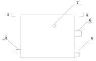
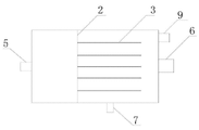
Fig. 1 is a cut-away view of the present utility model.
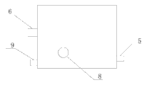
Fig. 2 is a front view of the present utility model.
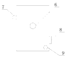
Fig. 3 is a rearview of the present utility model.
Fig. 4 is a left view of the present utility model.
Fig. 5 is a right view of the present utility model.
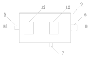
Fig. 6 is a vertical view of the present utility model.
Fig. 7 is that italic is every sand plate schematic diagram.
Fig. 8 is sliding sand plate schematic diagram.
Fig. 9 is the dividing plate schematic diagram.
Figure 10 is the A-A profile.
Figure 11 is the B-B profile.
Among the figure, the 1-casing, the 2-dividing plate, the 3-italic is every the sand plate, and 4-is slided sand plate, 5-clear water delivery port, 6-sand removal mouth, 7-dirt inlet, 8-access hole, 9-sewage draining exit, 10-filtering holes, 11-water hole, 12-observation port, 13-expansion chamber, 14-rest chamber, 15-water-supplying chamber.
The specific embodiment
Below in conjunction with the drawings and specific embodiments the utility model is described in detail.
Described oil well operation impurity sedimentation treating apparatus includes casing 1, dividing plate 2, and italic is slided sand plate 4, clear water delivery port 5 every sand plate 3, sand removal mouth 6, dirt inlet 7, access hole 8, sewage draining exit 9, filtering holes 10, water hole 11, observation port 12, expansion chamber 13, rest chamber 14, water-supplying chamber 15.
Italic all is provided with filtering holes 10 on sand plate 3 and sliding sand plate 4; Dividing plate 2 belows are provided with water hole 11; Water-supplying chamber 15 bottoms are provided with clear water delivery port 5; Expansion chamber 13 bottoms are provided with sand removal mouth 6, and top is provided with dirt inlet 7, and face the plate face of italic every sand plate 3; Rest chamber 14 bottoms are provided with sewage draining exit.
The aperture of the filtering holes 10 of italic on sand plate 3, the direction that flows into along sump oil reduces successively.
At first, sump oil enters into expansion chamber 13 by dirt inlet 7, filter every sand plate 3 each plate by italic successively, flow on the sliding sand plate 4 and refilter, sandstone class impurity can not be trapped on the sliding sand plate 4, because of sliding sand plate 4 is obliquely installed by italic filtering holes 10 on sand plate 3 and sliding sand plate 4, the sandstone class impurity that is detained can glide along sliding sand plate 4, and discharges from sand removal mouth 6.On sand plate 3 and sliding sand plate 4, filtering holes 10 is set all in italic, has guaranteed effective filtration of sump oil; The pore size filter of italic on sand plate 3 each plate reduces from front to back successively, more strengthened the filter effect of sump oil.
Then, the sump oil after the removal of impurities flows in the rest chamber 14 by the filtering holes 10 on the sliding sand plate 4, carries out water-oil separating after leaving standstill, water stratification occupies down, on oil reservoir occupied, it is temporary that the water hole 11 that the moisture content layer is provided with by dividing plate 2 bottoms enters water-supplying chamber 15, discharges by clear water delivery port 5 then.
At last, the dirt that is detained in the rest chamber 14 is discharged by sewage draining exit 9.
In addition, the water outlet of clear water delivery port 5 can be recycling once more, is used for sand-flushing, reduced the operation water consumption significantly, controlled operating cost.
Rest chamber 14 is provided with access hole 8, utilizes flangeseal, safeguards and maintenance in order to device; Expansion chamber 13 and water-supplying chamber 15 tops all are provided with observation port 12, can open the running status of observation device at any time.
Claims (3)
1. oil well operation impurity sedimentation treating apparatus includes casing (1), it is characterized in that: be provided with dividing plate (2), italic in the casing (1) every sand plate (3) and sliding sand plate (4); Dividing plate (2) vertically is arranged in the casing (1), and the one side is water-supplying chamber (15); Sliding sand plate (4) is arranged at the middle part of dividing plate (2) opposite side, and its side near dividing plate (2) is higher, and relative opposite side is lower, and sliding sand plate (4) top is expansion chamber (13), and the below is rest chamber (14); Italic is set up in parallel in sliding sand plate (4) top successively every sand plate (3); Italic is provided with filtering holes (10) every sand plate (3) and sliding sand plate (4); Dividing plate (2) below is provided with water hole (11).
2. oil well operation impurity sedimentation treating apparatus according to claim 1, it is characterized in that: described water-supplying chamber (15) bottom is provided with clear water delivery port (5); Described expansion chamber (13) bottom is provided with sand removal mouth (6), and top is provided with dirt inlet (7), and faces the plate face of italic every sand plate (3); Described rest chamber (14) bottom is provided with sewage draining exit (9).
3. oil well operation impurity sedimentation treating apparatus according to claim 1 is characterized in that: the aperture of the filtering holes (10) of described italic on sand plate (3), the direction that flows into along sump oil reduces successively.
Priority Applications (1)
| Application Number | Priority Date | Filing Date | Title |
|---|---|---|---|
| CN2010205138674U CN201815152U (en) | 2010-09-02 | 2010-09-02 | Impurity sedimentation processing device for oil well work |
Applications Claiming Priority (1)
| Application Number | Priority Date | Filing Date | Title |
|---|---|---|---|
| CN2010205138674U CN201815152U (en) | 2010-09-02 | 2010-09-02 | Impurity sedimentation processing device for oil well work |
Publications (1)
| Publication Number | Publication Date |
|---|---|
| CN201815152U true CN201815152U (en) | 2011-05-04 |
Family
ID=43913124
Family Applications (1)
| Application Number | Title | Priority Date | Filing Date |
|---|---|---|---|
| CN2010205138674U Expired - Fee Related CN201815152U (en) | 2010-09-02 | 2010-09-02 | Impurity sedimentation processing device for oil well work |
Country Status (1)
| Country | Link |
|---|---|
| CN (1) | CN201815152U (en) |
Cited By (4)
| Publication number | Priority date | Publication date | Assignee | Title |
|---|---|---|---|---|
| CN102518457A (en) * | 2012-01-12 | 2012-06-27 | 中煤北京煤矿机械有限责任公司 | Emulsified liquid box for hydraulic support general assembly workshop |
| CN105248251A (en) * | 2015-11-24 | 2016-01-20 | 张铁耀 | Water storage tank for irrigation |
| CN112774289A (en) * | 2019-11-07 | 2021-05-11 | 中国石油天然气股份有限公司 | Filter equipment and arrange and adopt system |
| CN115108650A (en) * | 2022-08-29 | 2022-09-27 | 湖南易净环保科技有限公司 | Automatic separator for glass fiber reinforced plastic oil sand and separation method thereof |
-
2010
- 2010-09-02 CN CN2010205138674U patent/CN201815152U/en not_active Expired - Fee Related
Cited By (6)
| Publication number | Priority date | Publication date | Assignee | Title |
|---|---|---|---|---|
| CN102518457A (en) * | 2012-01-12 | 2012-06-27 | 中煤北京煤矿机械有限责任公司 | Emulsified liquid box for hydraulic support general assembly workshop |
| CN105248251A (en) * | 2015-11-24 | 2016-01-20 | 张铁耀 | Water storage tank for irrigation |
| CN105248251B (en) * | 2015-11-24 | 2019-06-25 | 张铁耀 | Water tank is used in a kind of irrigation |
| CN112774289A (en) * | 2019-11-07 | 2021-05-11 | 中国石油天然气股份有限公司 | Filter equipment and arrange and adopt system |
| CN115108650A (en) * | 2022-08-29 | 2022-09-27 | 湖南易净环保科技有限公司 | Automatic separator for glass fiber reinforced plastic oil sand and separation method thereof |
| CN115108650B (en) * | 2022-08-29 | 2022-11-29 | 湖南易净环保科技有限公司 | Automatic separator for glass fiber reinforced plastic oil sand and separation method thereof |
Similar Documents
| Publication | Publication Date | Title |
|---|---|---|
| CN206793112U (en) | Tub oil water separator | |
| CN201815152U (en) | Impurity sedimentation processing device for oil well work | |
| CN206214880U (en) | Sediment separator | |
| CN107715513B (en) | Aeration grit chamber for sewage treatment and use method thereof | |
| CN206142879U (en) | Oil field filter -pressing water oil -water separator | |
| CN208261462U (en) | Oil field glass oil cup cleaning device | |
| CN108275801B (en) | Tunnel construction wastewater treatment process | |
| CN206503731U (en) | Anti-blocking immersible pump | |
| CN109610544B (en) | Prevent blockking up sand pumping machine utensil with multiunit takes out husky pipe | |
| CN205575826U (en) | Anti - flowing back processing system of sled multi -functional fracturing of dress formula | |
| CN210710983U (en) | Concrete sewage filtering device | |
| CN204824405U (en) | Silt particle separation cyclic utilization device | |
| CN205182357U (en) | Mine sedimentation tank | |
| CN102380254A (en) | Sedimentation treatment device for impurities of oil well operation | |
| CN204803361U (en) | Multi -functional quenching water tank | |
| CN104692555A (en) | Recycling and reutilization method and device for flow-back fracturing fluid | |
| CN204022596U (en) | A kind of oil-gas field fracturing waste liquor effective, harmless treatment unit | |
| CN102849906A (en) | Oil sludge separation apparatus and separation method | |
| CN206121239U (en) | Large -scale central transmission concentrator floats foam recovery unit | |
| CN104606941A (en) | Fiber rotary disk filtration tank for countryside small enterprises | |
| CN204778939U (en) | Oil -water separation apparatus | |
| CN210597454U (en) | Urban rainwater collection device | |
| CN211836447U (en) | Drum-type oil-water separator | |
| CN207877408U (en) | A kind of circulation Hand scarf device | |
| CN203944209U (en) | A kind of collecting-tank of industrial cool cycles water treatment system |
Legal Events
| Date | Code | Title | Description |
|---|---|---|---|
| C14 | Grant of patent or utility model | ||
| GR01 | Patent grant | ||
| C17 | Cessation of patent right | ||
| CF01 | Termination of patent right due to non-payment of annual fee |
Granted publication date: 20110504 Termination date: 20130902 |