CN201771663U - Mounting rack for quick connection type fuel injector - Google Patents
Mounting rack for quick connection type fuel injector Download PDFInfo
- Publication number
- CN201771663U CN201771663U CN2010205245515U CN201020524551U CN201771663U CN 201771663 U CN201771663 U CN 201771663U CN 2010205245515 U CN2010205245515 U CN 2010205245515U CN 201020524551 U CN201020524551 U CN 201020524551U CN 201771663 U CN201771663 U CN 201771663U
- Authority
- CN
- China
- Prior art keywords
- sleeve
- lug
- fuel injector
- utility
- model
- Prior art date
- Legal status (The legal status is an assumption and is not a legal conclusion. Google has not performed a legal analysis and makes no representation as to the accuracy of the status listed.)
- Expired - Fee Related
Links
Images

Landscapes
- Fuel-Injection Apparatus (AREA)
Abstract
Description
技术领域technical field
本实用新型涉及一种电喷摩托车构件,特别涉及电喷摩托车的快插式喷油器安装支架。The utility model relates to a component of an electric jet motorcycle, in particular to a fast plug-in fuel injector mounting bracket of the electric jet motorcycle.
背景技术Background technique
喷油器是电喷摩托车的重要部件,它将燃油以一定压力的形式雾化并喷入进气管内。目前,喷油器通常采用接套式支架安装于发动机进气管上,喷油器的进口与接套式支架之间以及接套式支架与油管之间均采用直接套入加卡箍固定的方式,装配的工艺较复杂,装配效率较低,并且油路检查维修不方便。另外,接套式支架为金属冲压件,不仅材料成本较高、通用性和生产一致性难以保障,而且必须做镀锌防锈处理,由此增加了工序和生产成本。接套式支架镀锌后,其内壁的光洁度较差,一方面会形成较大的安装阻力,影响装配的速度;另一方面,在接套式支架与喷油机及油管之间容易形成细小的间隙,从而产生渗油、泄漏等现象。The fuel injector is an important part of the EFI motorcycle, which atomizes the fuel at a certain pressure and sprays it into the intake pipe. At present, the fuel injector is usually installed on the engine intake pipe with a sleeve-type bracket, and the inlet of the fuel injector and the sleeve-type bracket, as well as between the sleeve-type bracket and the oil pipe, are directly inserted and fixed with a clamp , the assembly process is more complicated, the assembly efficiency is low, and the inspection and maintenance of the oil circuit is inconvenient. In addition, the socket-type bracket is a metal stamping part, which not only has high material cost, but also has difficulty in ensuring versatility and production consistency, and must be galvanized for anti-rust treatment, which increases the process and production costs. After the socket bracket is galvanized, the smoothness of the inner wall is poor. On the one hand, it will form a large installation resistance, which will affect the speed of assembly; The gap, resulting in oil seepage, leakage and so on.
实用新型内容Utility model content
本实用新型所要解决的技术问题在于提供一种能够方便喷油器安装的快插式支架。The technical problem to be solved by the utility model is to provide a quick-insert bracket that can facilitate the installation of the fuel injector.
本实用新型的技术方案如下:一种快插式喷油器安装支架,由套筒、定位管和支耳组成,其中套筒的筒口朝下,该套筒的筒底与定位管的下端连接,所述定位管的中心孔与套筒的内腔连通,并且定位管下部的外壁上设有环形凸台;在所述套筒的外壁上设有支耳,该支耳上开有圆形过孔。The technical scheme of the utility model is as follows: a fast plug-in fuel injector mounting bracket, which is composed of a sleeve, a positioning tube and a lug, wherein the mouth of the sleeve faces downward, and the bottom of the sleeve is connected to the lower end of the positioning tube , the central hole of the positioning tube communicates with the inner cavity of the sleeve, and an annular boss is provided on the outer wall of the lower part of the positioning tube; a lug is provided on the outer wall of the sleeve, and a circular lug is opened on the lug Via.
采用以上技术方案,套筒套装于喷油器的进口,螺栓穿过支耳上的圆形过孔,将本实用新型固定于发动机进气管上,而定位管插入油管快速插头中,定位管下部的环形凸台起定位作用,防止定位管从快速插头中退出。由此可见,本实用新型能够方便喷油器安装,不仅装配工艺简单,装配效率较高,而且拆装容易,油路检查维修方便。Using the above technical scheme, the sleeve is set on the inlet of the fuel injector, the bolt passes through the circular hole on the lug, and the utility model is fixed on the engine intake pipe, and the positioning pipe is inserted into the quick plug of the oil pipe, and the lower part of the positioning pipe The ring-shaped boss of the valve acts as a positioning function to prevent the positioning tube from withdrawing from the quick plug. It can be seen that the utility model can facilitate the installation of the fuel injector, not only the assembly process is simple, the assembly efficiency is high, but also the disassembly and assembly are easy, and the inspection and maintenance of the oil circuit is convenient.
所述套筒、定位管和支耳为一体结构,由尼龙通过注塑成型。这样一方面加工制作容易,成本较低、通用性和生产一致性好;另一方面,内、外表面的光洁度好,安装阻力小,进一步提高了装配速度,并能有效方防止渗油、泄漏等现象。The sleeve, the positioning tube and the lug are integrally formed by injection molding of nylon. In this way, on the one hand, the processing is easy, the cost is low, the versatility and the production consistency are good; on the other hand, the smoothness of the inner and outer surfaces is good, and the installation resistance is small, which further improves the assembly speed and can effectively prevent oil leakage and leakage. And so on.
为了方便将套筒套装于喷油器进口,所述套筒的筒口为喇叭形。In order to conveniently fit the sleeve on the inlet of the fuel injector, the mouth of the sleeve is trumpet-shaped.
在所述套筒下部的外壁上设有环槽,该环槽位于支耳的下方。环槽供卡箍安装,这样套筒套装于喷油器进口后,再通过卡箍固定,增强了套筒与喷油器连接的牢靠性。An annular groove is arranged on the outer wall of the lower part of the sleeve, and the annular groove is located below the lug. The ring groove is used for clamp installation, so that after the sleeve is set at the inlet of the fuel injector, it is fixed by the clamp, which enhances the reliability of the connection between the sleeve and the fuel injector.
有益效果:本实用新型具有设计巧妙、易于加工、成本低、通用性和生产一致性好等特点,能够方便喷油器安装,不仅装配工艺简单,装配效率较高,而且拆装容易,油路检查维修方便,并有效消除了渗油、泄漏等现象。Beneficial effects: the utility model has the characteristics of ingenious design, easy processing, low cost, versatility and good production consistency, and can facilitate the installation of the fuel injector. It is convenient for inspection and maintenance, and effectively eliminates oil seepage and leakage.
附图说明Description of drawings
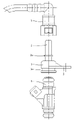
图1为本实用新型的结构示意图。Fig. 1 is the structural representation of the utility model.
图2为本实用新型的使用状态图。Fig. 2 is the use state diagram of the utility model.
具体实施方式Detailed ways
下面结合附图和实施例对本实用新型作进一步说明:Below in conjunction with accompanying drawing and embodiment the utility model is further described:
如图1、图2所示,本实用新型由套筒1、定位管2和支耳3组成,并且套筒1、定位管2和支耳3为一体结构,由尼龙通过注塑成型。所述套筒1的筒口朝下,套筒1的筒口为喇叭形,起引导的作用,以便于将套筒1套装于喷油器4的进口。在套筒1下部的外壁上设有环槽1a,环槽1a供卡箍安装,这样套筒1套装于喷油器4进口后,再通过卡箍固定,能够使套筒与喷油器之间连接牢靠,以避免发生脱落。所述套筒1的筒底与定位管2的下端相连,定位管2的轴线与套筒1的轴线在同一直线上,定位管2的中心孔与套筒1的内腔连通,并且定位管2下部的外壁上一体形成有环形凸台2a。所述定位管2插入油管快速插头5中,油管快速插头5通过油管与油泵连接。定位管2下部的环形凸台2a起定位作用,防止定位管2从快速插头5中退出。As shown in Figures 1 and 2, the utility model is composed of a
从图1中可知,在套筒1的外壁上一体形成有支耳3,该支耳3位于环槽1a的上方,且支耳3上开有圆形过孔3a。螺栓穿过支耳3上的圆形过孔3a,将本实用新型固定于发动机进气管上。As can be seen from FIG. 1 , a
Claims (4)
Priority Applications (1)
| Application Number | Priority Date | Filing Date | Title |
|---|---|---|---|
| CN2010205245515U CN201771663U (en) | 2010-09-10 | 2010-09-10 | Mounting rack for quick connection type fuel injector |
Applications Claiming Priority (1)
| Application Number | Priority Date | Filing Date | Title |
|---|---|---|---|
| CN2010205245515U CN201771663U (en) | 2010-09-10 | 2010-09-10 | Mounting rack for quick connection type fuel injector |
Publications (1)
| Publication Number | Publication Date |
|---|---|
| CN201771663U true CN201771663U (en) | 2011-03-23 |
Family
ID=43751509
Family Applications (1)
| Application Number | Title | Priority Date | Filing Date |
|---|---|---|---|
| CN2010205245515U Expired - Fee Related CN201771663U (en) | 2010-09-10 | 2010-09-10 | Mounting rack for quick connection type fuel injector |
Country Status (1)
| Country | Link |
|---|---|
| CN (1) | CN201771663U (en) |
Cited By (2)
| Publication number | Priority date | Publication date | Assignee | Title |
|---|---|---|---|---|
| CN106438337A (en) * | 2016-08-31 | 2017-02-22 | 重庆万力联兴实业(集团)有限公司 | Pump core oil outlet nozzle connector and flange plate nylon tube assembly of fuel pump |
| CN111022230A (en) * | 2019-12-19 | 2020-04-17 | 江门市大长江集团有限公司 | Oil pipe connection structure, engine and motorcycle |
-
2010
- 2010-09-10 CN CN2010205245515U patent/CN201771663U/en not_active Expired - Fee Related
Cited By (2)
| Publication number | Priority date | Publication date | Assignee | Title |
|---|---|---|---|---|
| CN106438337A (en) * | 2016-08-31 | 2017-02-22 | 重庆万力联兴实业(集团)有限公司 | Pump core oil outlet nozzle connector and flange plate nylon tube assembly of fuel pump |
| CN111022230A (en) * | 2019-12-19 | 2020-04-17 | 江门市大长江集团有限公司 | Oil pipe connection structure, engine and motorcycle |
Similar Documents
| Publication | Publication Date | Title |
|---|---|---|
| CN201771663U (en) | Mounting rack for quick connection type fuel injector | |
| CN212139312U (en) | Atomizer and electronic atomization device | |
| CN201322657Y (en) | Anti-vibration and anti-interference temperature sensor | |
| CN201284714Y (en) | Mounting frame for oil ejector of electric spraying motorcycle | |
| CN201183231Y (en) | Magnetic flow nipple socket wrench | |
| CN202812639U (en) | High-pressure-resistant component of quick joint | |
| CN201835960U (en) | Fuel rail assembly of engine | |
| CN206707885U (en) | A kind of new integrated air feeder structure | |
| CN202732034U (en) | Oil drain plug with temperature sensor | |
| CN207999323U (en) | Automobile oil nozzle pin | |
| CN205977499U (en) | Electricity spouts motorcycle single channel oil rail | |
| CN206092384U (en) | Fuel pump pump core goes out glib joint can dismantle connection structure with ring flange nylon tube | |
| CN205319420U (en) | New type connector | |
| CN201650538U (en) | Injector inspection device | |
| CN203636645U (en) | Sand hopper | |
| CN205503331U (en) | Remove greasy type diesel engine fuel sprayer | |
| CN202300761U (en) | Oil return pipe of injection pump of engine | |
| CN214533327U (en) | Electric injection air inlet pipe | |
| CN204387265U (en) | Gearbox dynamic flange fitting seat structure | |
| CN203906140U (en) | Gas inlet pipe of motorcycle engine | |
| CN202300743U (en) | Integral air inlet pipe for electronic fuel injection engine | |
| CN203098078U (en) | Carbureter air intake wind cap | |
| CN202937355U (en) | Novel air throttle assembly | |
| CN202683392U (en) | Clamping hoop type spraying nozzle | |
| CN203374403U (en) | Connecting steel tube assembly |
Legal Events
| Date | Code | Title | Description |
|---|---|---|---|
| C14 | Grant of patent or utility model | ||
| GR01 | Patent grant | ||
| CF01 | Termination of patent right due to non-payment of annual fee |
Granted publication date: 20110323 Termination date: 20170910 |
|
| CF01 | Termination of patent right due to non-payment of annual fee |