CN201766754U - Non-isolated type LED driving power supply having protection function - Google Patents
Non-isolated type LED driving power supply having protection function Download PDFInfo
- Publication number
- CN201766754U CN201766754U CN2010205185444U CN201020518544U CN201766754U CN 201766754 U CN201766754 U CN 201766754U CN 2010205185444 U CN2010205185444 U CN 2010205185444U CN 201020518544 U CN201020518544 U CN 201020518544U CN 201766754 U CN201766754 U CN 201766754U
- Authority
- CN
- China
- Prior art keywords
- photoelectric device
- power switch
- charge
- inductance coil
- led photoelectric
- Prior art date
- Legal status (The legal status is an assumption and is not a legal conclusion. Google has not performed a legal analysis and makes no representation as to the accuracy of the status listed.)
- Expired - Fee Related
Links
Images
Abstract
The utility model relates to a non-isolated type LED driving power supply having protection function, including a rectifying bridge of which an AC side is connected to the commercial power and a DC side is connected to an LED photoelectric device, a filtering capacitor and a chopper circuit composed of a pulse-width modulator and a power switch tube are connected in parallel between anode and cathode of DC output side of the rectifying bridge, the utility model is characterized in that an LED photoelectric device set and a charging/discharging capacitor are connected in parallel in a like polarity manner to form a capacitance charging/discharging circuit and are then connected with an isolation diode in series based on the same poles, then connected with an inductance coil in parallel to form an inductance discharging loop that is connected to output side of a power switch tube, when the power switch tube is of a short circuit fault, the inductance coil, the power switch tube and the rectifying bridge form a loop to make a fuse tube of the circuit to be broken, so as to protect the circuit.
Description
Technical field
The utility model relates to a kind of non-isolation type LED driving power with defencive function, belongs to LED drive electric power unit class.
Background technology
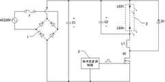
Non-isolation type LED driving power is because its circuit structure is simple, cost is low in the industry cycle to have a wide range of applications, existing non-isolation type LED driving power is that CN200720123346.6 is disclosed, accompanying drawing 1 is the circuit diagram after the disclosed a kind of non-isolation type LED driving power of CN200720123346.6 is simplified, this non-isolation type LED driving power comprises that AC side is connected in civil power one end, DC side is connected in the rectifier bridge of LED photoelectric device one side, between the both positive and negative polarity of the direct current outlet side of rectifier bridge and be connected with the chopper circuit that a filter capacitor and is made of pulse-width modulator and power switch pipe, several LED photoelectric devices are connected mutually, and constitute the capacitor discharge loop by the same polarity mode after in parallel with charge and discharge capacitance, connect with an inductance coil again and constitute a series connection circuit in described capacitor discharge loop, aforesaid series circuit is isolated second tube sheet formation in parallel inductive discharge loop with one again, described LED photoelectric device, the positive pole of charge and discharge capacitance and the negative pole of isolating diode are connected to the positive pole of rectifier bridge, and the anodal chopper circuit of the non-union end of the parallel circuits that described inductance coil and LED photoelectric device and charge and discharge capacitance constitute and described isolating diode is the outlet side of power switch pipe.In case the problem that the disclosed this non-isolation type LED driving power of CN200720123346.6 exists is the power switch pipe failed shorted, then the high direct voltage of rectifier bridge output will directly be loaded on LED photoelectric device and the charge and discharge capacitance, cause the damage of LED photoelectric device and charge and discharge capacitance, during reality is used, aforesaid power switch pipe often takes place with the situation that the form of short circuit breaks down, so further improved necessity is arranged.
Summary of the invention
The purpose of this utility model is to provide a kind of non-isolation type LED driving power with defencive function, to overcome the problem that prior art exists.
A kind of non-isolation type LED driving power of the present utility model with defencive function; comprise that AC side is connected in civil power one end; DC side is connected in the rectifier bridge of LED photoelectric device one side; between the both positive and negative polarity of the direct current outlet side of rectifier bridge and be connected with a filter capacitor and by pulse-width modulator; the chopper circuit that power switch pipe constitutes; its main points are that several LED photoelectric devices are connected mutually and constitute LED photoelectric device group; described LED photoelectric device group is in parallel by the same polarity mode with a charge and discharge capacitance; form the capacitor charge and discharge loop; the positive pole of described LED photoelectric device group and the positive pole of charge and discharge capacitance connect with the negative pole of an isolating diode again; the series circuit that forms is in parallel with an inductance coil again; form the inductive discharge loop; described LED photoelectric device group negative pole; one of the negative pole of charge and discharge capacitance and inductance coil is connected to the direct current output cathode of rectifier bridge, and the other end anodal and described inductance coil of described isolating diode is connected to the outlet side that chopper circuit is a power switch pipe.
This non-isolation type LED driving power of the present utility model with defencive function; when the circuit power switch pipe is short-circuited fault; rectifier bridge, inductance coil and power switch pipe form a short-circuited conducting sleeve; the protective tube of rectifier bridge AC side will disconnect; whole system will be protected, thereby the purpose of this utility model is achieved.
In the preferred embodiment that the utility model provides; described a kind of non-isolation type LED driving power with defencive function; comprise that AC side is connected in civil power one end; DC side is connected in the rectifier bridge of LED photoelectric device one side; between the both positive and negative polarity of the direct current outlet side of rectifier bridge and be connected with the chopper circuit that a filter capacitor and is made of pulse-width modulator and power switch pipe; in this preferred embodiment; several LED photoelectric devices are connected mutually and are formed LED photoelectric device group; described LED photoelectric device group is in parallel by the same polarity mode with a charge and discharge capacitance; form a capacitor discharge loop; LED photoelectric device group and charge and discharge capacitance by the same polarity mode in parallel after; the positive pole of described LED photoelectric device group and the positive pole of charge and discharge capacitance connect with the negative pole of an isolating diode again; be to connect by the mode that connects along polarity with isolating diode in described capacitor discharge loop; in parallel with an inductance coil again; form the inductive discharge loop; the negative pole of described LED photoelectric device group; one of the negative pole of charge and discharge capacitance and inductance coil is connected to the direct current outlet side positive pole of rectifier bridge; the other end anodal and described inductance coil of described isolating diode is connected to the outlet side that chopper circuit is a power switch pipe, and promptly described inductive discharge loop is connected between rectifier bridge direct current outlet side positive pole and the power switch pipe outlet side in the heteropolarity mode.
During work, when the power switch pipe conducting, direct current through rectifier bridge output forms the loop through inductance coil, power switch pipe and rectifier bridge, the inductance coil energy storage, at this moment, the LED photoelectric device is powered by charge and discharge capacitance, when power switch pipe ends, inductance coil discharges institute's electric energy stored, because inductance coil formed electric energy polarity when energy storage is opposite with the output voltage of rectifier bridge, so inductance coil is when discharging electric energy, inductance coil is powered to LED photoelectric device and charge and discharge capacitance through isolating diode.When power switch pipe is short-circuited fault, rectifier bridge, inductance coil and power switch tubular and short-circuited conducting sleeve, the protective tube of rectifier bridge AC side will be disconnected.
Description of drawings
Fig. 1 is the circuit diagram after the disclosed a kind of non-isolation type LED driving power of CN200720123346.6 is simplified.
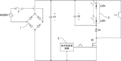
Fig. 2 is a kind of non-isolation type LED driving power circuit schematic diagram with defencive function that the utility model preferred embodiment provides.
1 is that rectifier bridge, 2 is that LED photoelectric device group, 3 is that pulse-width modulator, C1 are that filter capacitor, C2 are that charge and discharge capacitance, D1 are that isolating diode, L1 are that inductance coil, Q1 are that power switch pipe, F are that protective tube, LED1 to LEDn are the LED photoelectric device among each figure.
Embodiment
The utility model is described in further detail for a kind of non-isolation type LED driving power with defencive function that provides below with reference to the utility model preferred embodiment and accompanying drawing thereof.
As shown in Figure 2; a kind of non-isolation type LED driving power that provides in the utility model preferred embodiment with defencive function; comprise that AC side is connected in civil power one end; DC side is connected in the rectifier bridge 1 of LED photoelectric device one side; between the both positive and negative polarity of the direct current outlet side of rectifier bridge 1 and be connected with the chopper circuit that a filter capacitor C1 and is made of pulse-width modulator 3 and power switch pipe Q1; in this preferred embodiment; described pulse-width modulator 3 can be selected the TAC9918 chip for use; in this preferred embodiment; several LED photoelectric devices LED1 to LEDn connects mutually and forms LED photoelectric device group 2; described LED photoelectric device group 2 is in parallel by the same polarity mode with a charge and discharge capacitance C2; the parallel connection of so-called same polarity mode is the positive pole that the positive pole of charge and discharge capacitance C2 connects LED photoelectric device group 2, and the negative pole of charge and discharge capacitance C2 connects the negative pole of LED photoelectric device group 2.LED photoelectric device group 2 and a charge and discharge capacitance C2 form a capacitor discharge loop by the same polarity mode after in parallel, LED photoelectric device group 2 and charge and discharge capacitance C2 by the same polarity mode in parallel after, the interface of the positive pole of described LED photoelectric device group and the positive pole of charge and discharge capacitance C2 connects with the negative pole of an isolating diode D1 again, be to connect by the mode that connects along polarity with isolating diode D1 in described capacitor discharge loop, and then it is in parallel with an inductance coil L1, form the inductive discharge loop, the negative pole of described LED photoelectric device group, the negative pole of charge and discharge capacitance C1 and inductance coil L1 and interface is connected to the positive pole of rectifier bridge 1 direct current outlet side, the other end anodal and described inductance coil L1 of described isolating diode D1 is connected to the outlet side that chopper circuit is power switch pipe Q1, and promptly described inductive discharge loop is connected between rectifier bridge 1 direct current outlet side positive pole and the power switch pipe Q1 outlet side in the heteropolarity mode.
A kind of non-isolation type LED driving power with defencive function of this preferred embodiment, when power switch pipe Q1 conducting, rectifier bridge 1, inductance coil L1 and power switch pipe Q1 form loop, inductance coil L1 energy storage.At this moment; charge and discharge capacitance C2 is to 2 power supplies of LED photoelectric device group; when power switch pipe Q1 ends; inductance coil L1 powers to charge and discharge capacitance C2 charging and to LED photoelectric device group 2 through isolating diode D1; when circuit breaks down, during power switch pipe Q1 short circuit, rectifier bridge 1, inductance coil L1 and power switch pipe Q1 form a short-circuited conducting sleeve; the protective tube F of rectifier bridge 1 AC side will be disconnected, thereby entire circuit is protected.
In sum; a kind of non-isolation type LED driving power of the present utility model with defencive function; comprise that AC side is connected in civil power one end; DC side is connected in the rectifier bridge of LED photoelectric device one side; between the both positive and negative polarity of the direct current outlet side of rectifier bridge and be connected with the chopper circuit that a filter capacitor and a pulse-width modulator and power switch pipe constitute; its main points are that LED photoelectric device group and charge and discharge capacitance connect in parallel with an inductance coil by the same polarity mode capacitor charge and discharge loop that forms in parallel with the suitable polarity of an isolating diode again; form the inductive discharge loop and be connected to the outlet side of power switch pipe; when power switch pipe is short-circuited fault; inductance coil; form the loop between power switch pipe and rectifier bridge; protective tube in the circuit is opened circuit, thereby circuit is protected.
The above only is an embodiment of the present utility model.But the utility model protection range is not limited thereto.Anyly be familiar with those skilled in the art in the technical scope that the utility model discloses; the variation that can expect easily or replacement; all should be encompassed within the protection range of the present utility model, therefore, protection range of the present utility model should be as the criterion with the protection range of claim.
Claims (2)
1.
A kind of non-isolation type LED driving power with defencive function; comprise that AC side is connected in civil power one end; DC side is connected in the rectifier bridge of LED photoelectric device one side; between the both positive and negative polarity of the direct current outlet side of rectifier bridge and be connected with a filter capacitor and by pulse-width modulator; the chopper circuit that power switch pipe constitutes; it is characterized in that several LED photoelectric devices are connected mutually constitutes LED photoelectric device group; described LED photoelectric device group is in parallel by the same polarity mode with a charge and discharge capacitance; form the capacitor charge and discharge loop; the positive pole of described LED photoelectric device group and the positive pole of charge and discharge capacitance connect with the negative pole of an isolating diode again; the series circuit that forms is in parallel with an inductance coil again; form the inductive discharge loop; described LED photoelectric device group negative pole; one of the negative pole of charge and discharge capacitance and inductance coil is connected to the positive pole of rectifier bridge, and the other end anodal and described inductance coil of described isolating diode is connected to the outlet side that chopper circuit is a power switch pipe.
2.
A kind of non-isolation type LED driving power with defencive function according to claim 1 is characterized in that pulse-width modulator is the TAC9918 chip.
Priority Applications (1)
| Application Number | Priority Date | Filing Date | Title |
|---|---|---|---|
| CN2010205185444U CN201766754U (en) | 2010-09-07 | 2010-09-07 | Non-isolated type LED driving power supply having protection function |
Applications Claiming Priority (1)
| Application Number | Priority Date | Filing Date | Title |
|---|---|---|---|
| CN2010205185444U CN201766754U (en) | 2010-09-07 | 2010-09-07 | Non-isolated type LED driving power supply having protection function |
Publications (1)
| Publication Number | Publication Date |
|---|---|
| CN201766754U true CN201766754U (en) | 2011-03-16 |
Family
ID=43719361
Family Applications (1)
| Application Number | Title | Priority Date | Filing Date |
|---|---|---|---|
| CN2010205185444U Expired - Fee Related CN201766754U (en) | 2010-09-07 | 2010-09-07 | Non-isolated type LED driving power supply having protection function |
Country Status (1)
| Country | Link |
|---|---|
| CN (1) | CN201766754U (en) |
Cited By (6)
| Publication number | Priority date | Publication date | Assignee | Title |
|---|---|---|---|---|
| WO2012136044A1 (en) * | 2011-04-02 | 2012-10-11 | 英飞特电子(杭州)有限公司 | Method for controlling auxiliary power circuit of dual-line dimmer |
| CN102892223A (en) * | 2011-07-21 | 2013-01-23 | 罗姆股份有限公司 | Lighting system |
| CN103025021A (en) * | 2012-12-14 | 2013-04-03 | 西安铨芯电子有限公司 | Step-down light emitting diode (LED) drive circuit based on electrical inductance discharge time modulation |
| CN103687167A (en) * | 2012-09-14 | 2014-03-26 | 东芝照明技术株式会社 | Luminaire |
| WO2014153787A1 (en) * | 2013-03-27 | 2014-10-02 | 深圳市华星光电技术有限公司 | Led backlight driving circuit and backlight module |
| CN105720843A (en) * | 2016-04-12 | 2016-06-29 | 北京联合大学 | Method and device for improving utilization efficiency of power frequency alternating current energy |
-
2010
- 2010-09-07 CN CN2010205185444U patent/CN201766754U/en not_active Expired - Fee Related
Cited By (12)
| Publication number | Priority date | Publication date | Assignee | Title |
|---|---|---|---|---|
| WO2012136044A1 (en) * | 2011-04-02 | 2012-10-11 | 英飞特电子(杭州)有限公司 | Method for controlling auxiliary power circuit of dual-line dimmer |
| CN102752900A (en) * | 2011-04-02 | 2012-10-24 | 英飞特电子(杭州)股份有限公司 | Method for controlling auxiliary source circuit of two-line light modulator |
| CN102752900B (en) * | 2011-04-02 | 2014-10-29 | 英飞特电子(杭州)股份有限公司 | Method for controlling auxiliary source circuit of two-line light modulator |
| CN102892223A (en) * | 2011-07-21 | 2013-01-23 | 罗姆股份有限公司 | Lighting system |
| US9185753B2 (en) | 2011-07-21 | 2015-11-10 | Rohm Co., Ltd. | Lighting system |
| CN102892223B (en) * | 2011-07-21 | 2016-08-17 | 罗姆股份有限公司 | Illuminator |
| CN103687167A (en) * | 2012-09-14 | 2014-03-26 | 东芝照明技术株式会社 | Luminaire |
| CN103025021A (en) * | 2012-12-14 | 2013-04-03 | 西安铨芯电子有限公司 | Step-down light emitting diode (LED) drive circuit based on electrical inductance discharge time modulation |
| WO2014153787A1 (en) * | 2013-03-27 | 2014-10-02 | 深圳市华星光电技术有限公司 | Led backlight driving circuit and backlight module |
| GB2526952A (en) * | 2013-03-27 | 2015-12-09 | Shenzhen China Star Optoelect | LED backlight driving circuit and backlight module |
| GB2526952B (en) * | 2013-03-27 | 2019-12-25 | Shenzhen China Star Optoelect | LED backlight driving circuit and backlight module |
| CN105720843A (en) * | 2016-04-12 | 2016-06-29 | 北京联合大学 | Method and device for improving utilization efficiency of power frequency alternating current energy |
Similar Documents
| Publication | Publication Date | Title |
|---|---|---|
| CN101882879B (en) | Circuit converting constant current source to constant voltage source and light using same | |
| CN201766754U (en) | Non-isolated type LED driving power supply having protection function | |
| CN102130596B (en) | Switching converter with wide input voltage range | |
| CN104184349B (en) | Flyback switching power supply | |
| CN103326325A (en) | Short-circuit and low-voltage protective circuit of output of switching power source | |
| CN105979661A (en) | Time delay illumination circuit and device | |
| CN104967195A (en) | Electric automobile charging system achieving intelligent frequency conversion control | |
| CN104145529A (en) | Led light source | |
| CN103123882A (en) | Intelligent controller of bistable permanent-magnet vacuum circuit breaker | |
| CN203984066U (en) | Intelligent charger circuit | |
| CN201430466Y (en) | Electronic emergency power supply for emergency light | |
| CN206673569U (en) | The output protection circuit of Switching Power Supply | |
| CN104968070B (en) | A kind of LED drive circuit | |
| CN201430719Y (en) | Electronic emergency inverter | |
| CN202652054U (en) | Passive lossless snubber circuit suitable for single-tube flyback | |
| CN101277071A (en) | Power supply circuit | |
| CN104080221B (en) | A kind of LED drive circuit and LED light | |
| CN104868708A (en) | Power-on buffering and bus discharge circuit for frequency converter | |
| CN205490112U (en) | Automatic discharge device | |
| CN203787352U (en) | Relay drive circuit | |
| CN204334331U (en) | The fans drive power supply of vehicle-mounted heater | |
| CN102570587A (en) | Method for high-power distributed power supply | |
| CN102480134B (en) | A kind of solar recharging system | |
| CN205544356U (en) | Adopt constant voltage charge circuit that floats ground formula | |
| CN103887996A (en) | Transformer-isolated soft commutation chopping power supply main circuit for storage battery |
Legal Events
| Date | Code | Title | Description |
|---|---|---|---|
| C14 | Grant of patent or utility model | ||
| GR01 | Patent grant | ||
| CF01 | Termination of patent right due to non-payment of annual fee |
Granted publication date: 20110316 Termination date: 20170907 |
|
| CF01 | Termination of patent right due to non-payment of annual fee |