CN201749934U - Dielectric resonator and dielectric filter - Google Patents
Dielectric resonator and dielectric filter Download PDFInfo
- Publication number
- CN201749934U CN201749934U CN2010201389334U CN201020138933U CN201749934U CN 201749934 U CN201749934 U CN 201749934U CN 2010201389334 U CN2010201389334 U CN 2010201389334U CN 201020138933 U CN201020138933 U CN 201020138933U CN 201749934 U CN201749934 U CN 201749934U
- Authority
- CN
- China
- Prior art keywords
- dielectric
- metab
- resonance post
- cavity
- dielectric resonator
- Prior art date
- Legal status (The legal status is an assumption and is not a legal conclusion. Google has not performed a legal analysis and makes no representation as to the accuracy of the status listed.)
- Expired - Fee Related
Links
Images


Abstract
The utility model discloses a dielectric resonator and a dielectric filter. In the technical scheme, detachable connection of a resonant column and a cavity is realized through a metal base, and when the metal base is locked on the cavity through screws, the metal base can be tightly contacted with the cavity, thereby satisfying radio frequency requirements. Moreover, the screws fixing the metal base are integrated with the metal base, and no reserved space is needed for the screws in the dielectric resonant column, so the resonant column can be designed without taking the size of the fixing screws into accounts, thereby making the design of the resonant column more flexible, increasing the Q value of the resonant cavity, and reducing the insertion loss of the resonant cavity.
Description
Technical field
The utility model relates to the dielectric filter technical field, is specifically related to dielectric resonator and dielectric filter.
Background technology
Dielectric filter be the low-loss, high-k, frequency-temperature coefficient and the thermal coefficient of expansion that utilize medium ceramic material little, be characterized in inserting good, the narrow bandwidth of little, the anti-power of loss.
Referring to Fig. 1, this figure is that horizontal magnetic (transverse magnetic, mainly be made up of dielectric resonance post and metallic cavity by the TM) schematic diagram of mould dielectric filter.According to electromagnetic principle, resonator is when operate as normal, and there is CURRENT DISTRIBUTION dielectric resonance post 101 upper and lower end faces and metallic cavity 102 junctions.If it is bad that the upper and lower end face of dielectric resonance post 101 contacts with metallic cavity 102, can cause leakage of current on the one hand, increased the contact resistance of dielectric resonance post 101 upper and lower end faces and metallic cavity 102 on the other hand, increased loss.Therefore, the medium of resonator contacts well very importantly in the TM mould dielectric filter with metallic cavity 102 upper and lower surfaces, otherwise can cause current loss to increase, thereby influence the performance of filter.
In research and practice process to prior art, inventor of the present utility model finds, in the prior art, the lower surface of dielectric resonance post is welded direct on the metallic cavity, though can solve the problem that conducts, but but not easy to operate, because the restriction of the internal structure of cavity, welding is difficulty relatively, simultaneously after the welding, in case the resonance post goes wrong, because welding to the destruction on the surface of cavity, can't be keeped in repair and debug by changing the resonance post.
Summary of the invention
Dielectric resonator that the utility model provides and dielectric filter can be changed the resonance post easily, have improved the maintainability of dielectric filter.
A kind of dielectric resonator that the utility model embodiment provides, comprise dielectric resonance post, cavity, cover plate, described dielectric resonance post is arranged in the described cavity, it is characterized in that, also comprise: the metab of dielectric resonance post, the bottom surface of described dielectric resonance post is welded in first end of described metab, and on described cavity bottom surface, described screw and described metab are one-body molded by the screw on the metab for described metab.
Preferably, described resonance post is a cylindrical shape, and first end on the described metab is provided with the circle location concave station that is used to locate described resonance post, and the diameter of described location concave station is a bit larger tham the diameter of described dielectric resonance post.
Preferably, described resonance post is a cylindrical shape, and there is through hole vertically at described resonance post middle part, and first end is provided with reference column on the described metab, and described reference column inserts described through hole, and the dielectric resonance post is positioned.
Preferably, metalized is adopted in described dielectric resonance post bottom surface, metal level after the described metallization and the welding of described metab first end.
Preferably, the periphery of described metab is that polygon or described metab periphery are provided with the screens that is used to be rotated.
Preferably, the contact-making surface periphery of second end of described metab and cavity is provided with the pointed tooth that is used to reduce described metab and cavity bottom surface contact area.
A kind of dielectric filter that the utility model embodiment provides comprises one or more above-mentioned dielectric resonators, carries out the signal coupling by the coupling window that is provided with between described each dielectric resonator.
Dielectric resonator that the utility model embodiment provides and dielectric filter, realized detachable connection between resonance post and the cavity by metab, when being locked on the cavity, can guarantee that metab closely contacts with cavity, satisfies radio frequency requirement to metab with screw.And screw and metab that the fixing metal base is used are integrated, needn't be the screw headspace in the dielectric resonance post, make the design of resonance post can not consider the dimensional problem of hold-down screw, and be more flexible.Improve the Q value of resonant cavity, reduced the insertion loss of resonant cavity.
Description of drawings
In order to be illustrated more clearly in the technical scheme among the utility model embodiment, the accompanying drawing of required use is done to introduce simply in will describing embodiment below, apparently, accompanying drawing in describing below only is embodiment more of the present utility model, for those of ordinary skills, under the prerequisite of not paying creative work, can also obtain other accompanying drawing according to these accompanying drawings.
Fig. 1 is the schematic diagram of existing transverse magnetic mode dielectric filter;
Fig. 2 is the cross-sectional view of the utility model embodiment dielectric resonator;
Fig. 3 is the three-dimensional cutaway view of the utility model embodiment medium resonator;
Fig. 4 is a kind of location structure schematic diagram of the utility model medium resonance post metab;
Fig. 5 is the another kind of location structure schematic diagram of the utility model medium resonance post metab;
Fig. 6 is the partial structurtes schematic diagram of the utility model embodiment dielectric resonator.
Embodiment
Below in conjunction with the accompanying drawing among the utility model embodiment, the technical scheme among the utility model embodiment is clearly and completely described, obviously, described embodiment only is the utility model part embodiment, rather than whole embodiment.Based on the embodiment in the utility model, those of ordinary skills are not making the every other embodiment that is obtained under the creative work prerequisite, all belong to the scope of the utility model protection.
Embodiment one, a kind of dielectric resonator, structural representation as shown in Figure 2, comprise dielectric resonance post 210, cavity 220, described dielectric resonance post 210 is arranged in the described cavity 220, it is characterized in that, also comprise: the metab 230 of dielectric resonance post 210, the bottom surface of described dielectric resonance post 210 is welded in first end 231 of described metab 230, described metab 230 is fixed on described cavity 220 bottom surfaces by the screw on the metab 230 233, and described screw 233 is one-body molded with described metab.Be appreciated that the dielectric resonator that present embodiment provides also comprises conventional components such as cover plate, only show among the figure and the utility model relevant portion that concrete structure does not constitute restriction of the present utility model.
Consult shown in Figure 3ly in the lump, described dielectric resonance post 210 generally can cylindrical shape, and first end of described metab also can be cylindrical shape, and described metab 230 peripheries are provided with the screens 234 that is used to be rotated.Described screens be used to cooperate throw with resonance post metab by described incorporate screw in the bottom of cavity.Certain described metab periphery also can be polygon, is rotated to be used for installation personnel, and what present embodiment was emphasized is, the metab periphery is provided with the structure that can make things convenient for the installation personnel rotation, and concrete structure does not constitute restriction of the present utility model.
Among the utility model embodiment, the location of dielectric resonance post can be provided with location structure on described metab for convenience, provides two kinds of locate modes to describe below:
Mode one, referring to shown in Figure 4, structural representation for a kind of metab with location structure, first end on the described metab is provided with the circle location concave station 2311 that is used to locate described resonance post, and the diameter of described location concave station is a bit larger tham the diameter of described dielectric resonance post.
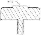
Mode two, described resonance post are cylindrical shape, there is through hole vertically at described resonance post middle part, referring to shown in Figure 5, structural representation for the metab of another kind band location structure, first end is provided with reference column 2312 on the described metab, described reference column inserts described through hole, and the dielectric resonance post is positioned.
Among the utility model embodiment, metalized is adopted in described dielectric resonance post 210 bottom surfaces, and metal level after the described metallization and the welding of described metab first end like this can be so that resonance post bottom surface and metal pedestal be electrically connected reliably.
As shown in Figure 6, among the utility model embodiment, second end 232 of described metab 230 and the contact-making surface periphery of cavity are provided with the pointed tooth 240 that is used to increase the pressure between described metab and the cavity.Among Fig. 6, described pointed tooth 240 cross sections are triangle, are appreciated that to be appreciated that described pointed tooth cross section all right or circular arc or trapezoidal or rectangle etc.First end 231 of metab 230 is provided with concave station the dielectric resonance post is positioned among the figure.
Embodiment two, a kind of dielectric filter comprise the dielectric resonator described in one or more embodiment one, carry out the signal coupling by the coupling window that is provided with between described each dielectric resonator.
More than dielectric resonator and dielectric filter that the utility model embodiment is provided be described in detail, wherein:
Dielectric resonator that the utility model embodiment provides and dielectric filter, realized detachable connection between resonance post and the cavity by metab, when being locked on the cavity, can guarantee that metab closely contacts with cavity, satisfies radio frequency requirement to metab with screw.And screw and metab that the fixing metal base is used are integrated, needn't be the screw headspace in the dielectric resonance post, make the design of resonance post can not consider the dimensional problem of hold-down screw, and be more flexible.
Used specific case herein principle of the present utility model and execution mode are set forth, the explanation of above embodiment just is used for helping to understand method of the present utility model and core concept thereof; Simultaneously, for one of ordinary skill in the art, according to thought of the present utility model, the part that all can change in specific embodiments and applications, in sum, this description should not be construed as restriction of the present utility model.
Claims (7)
1. dielectric resonator, comprise dielectric resonance post, cavity, cover plate, described dielectric resonance post is arranged in the described cavity, it is characterized in that, also comprise: the metab of dielectric resonance post, the bottom surface of described dielectric resonance post is welded in first end of described metab, and on described cavity bottom surface, described screw and described metab are one-body molded by the screw on the metab for described metab.
2. dielectric resonator as claimed in claim 1, it is characterized in that, described resonance post is a cylindrical shape, and first end on the described metab is provided with the circle location concave station that is used to locate described resonance post, and the diameter of described location concave station is a bit larger tham the diameter of described dielectric resonance post.
3. dielectric resonator as claimed in claim 1 is characterized in that, described resonance post is a cylindrical shape, there is through hole vertically at described resonance post middle part, first end is provided with reference column on the described metab, and described reference column inserts described through hole, and the dielectric resonance post is positioned.
4. dielectric resonator as claimed in claim 1 is characterized in that, metalized is adopted in described dielectric resonance post bottom surface, metal level after the described metallization and the welding of described metab first end.
5. as any described dielectric resonator of claim 1 to 4, it is characterized in that the periphery of described metab is that polygon or described metab periphery are provided with the screens that is used to be rotated.
6. dielectric resonator as claimed in claim 5, second end of described metab and the contact-making surface periphery of cavity are provided with the pointed tooth that is used to reduce described metab and cavity bottom surface contact area.
7. a dielectric filter comprises any described dielectric resonator of one or more claims 1 to 6, carries out the signal coupling by the coupling window that is provided with between described each dielectric resonator.
Priority Applications (1)
| Application Number | Priority Date | Filing Date | Title |
|---|---|---|---|
| CN2010201389334U CN201749934U (en) | 2010-03-17 | 2010-03-17 | Dielectric resonator and dielectric filter |
Applications Claiming Priority (1)
| Application Number | Priority Date | Filing Date | Title |
|---|---|---|---|
| CN2010201389334U CN201749934U (en) | 2010-03-17 | 2010-03-17 | Dielectric resonator and dielectric filter |
Publications (1)
| Publication Number | Publication Date |
|---|---|
| CN201749934U true CN201749934U (en) | 2011-02-16 |
Family
ID=43584606
Family Applications (1)
| Application Number | Title | Priority Date | Filing Date |
|---|---|---|---|
| CN2010201389334U Expired - Fee Related CN201749934U (en) | 2010-03-17 | 2010-03-17 | Dielectric resonator and dielectric filter |
Country Status (1)
| Country | Link |
|---|---|
| CN (1) | CN201749934U (en) |
Cited By (7)
| Publication number | Priority date | Publication date | Assignee | Title |
|---|---|---|---|---|
| CN103000983A (en) * | 2012-12-14 | 2013-03-27 | 中兴通讯股份有限公司 | TM dielectric resonator, realizing method thereof and TM dielectric filter |
| GB2499725A (en) * | 2012-02-24 | 2013-08-28 | Radio Design Ltd | Cavity filter with dielectric rod attached to a wall of the cavity housing via securing means |
| CN103296351A (en) * | 2012-02-29 | 2013-09-11 | 深圳光启创新技术有限公司 | Filter |
| CN103531869A (en) * | 2012-07-03 | 2014-01-22 | 罗森伯格(上海)通信技术有限公司 | TM mold dielectric filter |
| CN103840239A (en) * | 2012-11-20 | 2014-06-04 | 深圳光启创新技术有限公司 | Resonant cavity, filter and electromagnetic wave equipment |
| EP2933876A4 (en) * | 2012-12-14 | 2015-12-23 | Zte Corp | Tm medium resonator, method of implementing same, and tm medium filter |
| WO2017088195A1 (en) * | 2015-11-28 | 2017-06-01 | 华为技术有限公司 | Dielectric resonator and filter |
-
2010
- 2010-03-17 CN CN2010201389334U patent/CN201749934U/en not_active Expired - Fee Related
Cited By (13)
| Publication number | Priority date | Publication date | Assignee | Title |
|---|---|---|---|---|
| GB2499725A (en) * | 2012-02-24 | 2013-08-28 | Radio Design Ltd | Cavity filter with dielectric rod attached to a wall of the cavity housing via securing means |
| GB2499725B (en) * | 2012-02-24 | 2019-11-13 | Radio Design Ltd | Filter apparatus and method of manufacture thereof |
| CN103296351B (en) * | 2012-02-29 | 2019-02-22 | 深圳光启创新技术有限公司 | A kind of filter |
| CN103296351A (en) * | 2012-02-29 | 2013-09-11 | 深圳光启创新技术有限公司 | Filter |
| CN103531869B (en) * | 2012-07-03 | 2017-11-24 | 罗森伯格(上海)通信技术有限公司 | A kind of TM moulds dielectric filter |
| CN103531869A (en) * | 2012-07-03 | 2014-01-22 | 罗森伯格(上海)通信技术有限公司 | TM mold dielectric filter |
| CN103840239A (en) * | 2012-11-20 | 2014-06-04 | 深圳光启创新技术有限公司 | Resonant cavity, filter and electromagnetic wave equipment |
| EP2933876A4 (en) * | 2012-12-14 | 2015-12-23 | Zte Corp | Tm medium resonator, method of implementing same, and tm medium filter |
| JP2016503976A (en) * | 2012-12-14 | 2016-02-08 | ゼットティーイー コーポレーションZte Corporation | TM medium resonator, realization method thereof, and TM medium filter |
| CN103000983B (en) * | 2012-12-14 | 2017-04-12 | 中兴通讯股份有限公司 | TM dielectric resonator, realizing method thereof and TM dielectric filter |
| CN103000983A (en) * | 2012-12-14 | 2013-03-27 | 中兴通讯股份有限公司 | TM dielectric resonator, realizing method thereof and TM dielectric filter |
| WO2017088195A1 (en) * | 2015-11-28 | 2017-06-01 | 华为技术有限公司 | Dielectric resonator and filter |
| US10847855B2 (en) | 2015-11-28 | 2020-11-24 | Huawei Technologies Co., Ltd. | Dielectric resonator and filter comprising a body with a resonant hole surrounded by an encirclement wall having a ring shaped exposed dielectric area |
Similar Documents
| Publication | Publication Date | Title |
|---|---|---|
| CN201749934U (en) | Dielectric resonator and dielectric filter | |
| CN201749933U (en) | Dielectric resonator and dielectric filter | |
| KR101479152B1 (en) | Transverse magnetic mode dielectric resonator and base station | |
| CN201985225U (en) | Medium filter | |
| CN101626101A (en) | Cavity medium filter and out-band rejection method | |
| CN202103148U (en) | Coupling structure of dielectric resonator and coaxial cavity resonator | |
| CN102324617B (en) | Two-end-grounded TM (Transverse Magnetic) mode medium resonator | |
| CN201359668Y (en) | LCD monitor | |
| WO2011113279A1 (en) | Dielectric resonator, elastic conductive shield piece, dielectric filter and communication device | |
| CN201117780Y (en) | Coaxial cavity resonator coupled structure | |
| CN104009276A (en) | Dielectric resonator, assembly method and dielectric filter | |
| CN205406688U (en) | TE mould dielectric resonator device | |
| CN202333087U (en) | TM (transverse magnetic) mode medium filter | |
| CN112271424A (en) | Dielectric resonator, filter, duplexer, multiplexer and communication base station | |
| CN102299438B (en) | Airtight-type electric connector | |
| CN203967025U (en) | The tube core of magnetron and magnetron | |
| CN101719578B (en) | Folding filter | |
| CN202363572U (en) | Dielectric filter and dielectric resonator thereof | |
| CN101983006B (en) | Construction method of compact electromagnetic band gap (EBG) structure for eliminating high speed circuit noise | |
| CN202285267U (en) | Medium filter, medium resonator, cover plate unit and communication equipment | |
| CN209357887U (en) | The double short filters of TM mould medium | |
| CN201340898Y (en) | TD-SCDMA surface mounted circulator | |
| CN102544648B (en) | Dielectric filter and multiplexer | |
| CN102170061B (en) | Airtight type electric connector | |
| CN208142943U (en) | A kind of stator punching and three-phase motor |
Legal Events
| Date | Code | Title | Description |
|---|---|---|---|
| C14 | Grant of patent or utility model | ||
| GR01 | Patent grant | ||
| CF01 | Termination of patent right due to non-payment of annual fee | ||
| CF01 | Termination of patent right due to non-payment of annual fee |
Granted publication date: 20110216 Termination date: 20160317 |