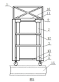
CN201730624U - Construction work vehicle for subway region tunnel - Google Patents
Construction work vehicle for subway region tunnel Download PDFInfo
- Publication number
- CN201730624U CN201730624U CN2010202075334U CN201020207533U CN201730624U CN 201730624 U CN201730624 U CN 201730624U CN 2010202075334 U CN2010202075334 U CN 2010202075334U CN 201020207533 U CN201020207533 U CN 201020207533U CN 201730624 U CN201730624 U CN 201730624U
- Authority
- CN
- China
- Prior art keywords
- horizontal
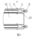
- staircase
- right angle
- rotating shaft
- roller
- Prior art date
- Legal status (The legal status is an assumption and is not a legal conclusion. Google has not performed a legal analysis and makes no representation as to the accuracy of the status listed.)
- Expired - Lifetime
Links
Images


Abstract
Description
Claims (2)
Priority Applications (1)
| Application Number | Priority Date | Filing Date | Title |
|---|---|---|---|
| CN2010202075334U CN201730624U (en) | 2010-05-28 | 2010-05-28 | Construction work vehicle for subway region tunnel |
Applications Claiming Priority (1)
| Application Number | Priority Date | Filing Date | Title |
|---|---|---|---|
| CN2010202075334U CN201730624U (en) | 2010-05-28 | 2010-05-28 | Construction work vehicle for subway region tunnel |
Publications (1)
| Publication Number | Publication Date |
|---|---|
| CN201730624U true CN201730624U (en) | 2011-02-02 |
Family
ID=43521781
Family Applications (1)
| Application Number | Title | Priority Date | Filing Date |
|---|---|---|---|
| CN2010202075334U Expired - Lifetime CN201730624U (en) | 2010-05-28 | 2010-05-28 | Construction work vehicle for subway region tunnel |
Country Status (1)
| Country | Link |
|---|---|
| CN (1) | CN201730624U (en) |
Cited By (3)
| Publication number | Priority date | Publication date | Assignee | Title |
|---|---|---|---|---|
| CN102372010A (en) * | 2011-08-17 | 2012-03-14 | 中国铁建电气化局集团第一工程有限公司 | Over-barrier wheel system, over-barrier method and limiting wheels of vehicle body for tunnel |
| CN112360172A (en) * | 2018-11-22 | 2021-02-12 | 李丽容 | Roller assembly suitable for horizontal net connecting support structure outside outward-extending type frame |
| CN114825177A (en) * | 2022-04-27 | 2022-07-29 | 中铁六局集团有限公司 | High-altitude pipeline installation construction method in circular cross-section tunnel |
-
2010
- 2010-05-28 CN CN2010202075334U patent/CN201730624U/en not_active Expired - Lifetime
Cited By (3)
| Publication number | Priority date | Publication date | Assignee | Title |
|---|---|---|---|---|
| CN102372010A (en) * | 2011-08-17 | 2012-03-14 | 中国铁建电气化局集团第一工程有限公司 | Over-barrier wheel system, over-barrier method and limiting wheels of vehicle body for tunnel |
| CN112360172A (en) * | 2018-11-22 | 2021-02-12 | 李丽容 | Roller assembly suitable for horizontal net connecting support structure outside outward-extending type frame |
| CN114825177A (en) * | 2022-04-27 | 2022-07-29 | 中铁六局集团有限公司 | High-altitude pipeline installation construction method in circular cross-section tunnel |
Similar Documents
| Publication | Publication Date | Title |
|---|---|---|
| CN101514586B (en) | Hanger rail type electric hanging boat and construction method thereof | |
| CN101787891B (en) | Station-crossing construction method and station-crossing construction device of wheel type mobile foundation | |
| CN201610631U (en) | Traction and movable type lifting platform for construction | |
| CN201730624U (en) | Construction work vehicle for subway region tunnel | |
| CN107161818A (en) | A kind of automatically controlled lowering or hoisting gear of construction | |
| CN209210319U (en) | It drives a vehicle dedicated maintenance hanging basket | |
| CN211174116U (en) | Shield tunnel pipeline moving device | |
| CN103171970B (en) | A kind of aloft work track mounting system and installation method thereof | |
| CN210263867U (en) | Climb a passageway plate turnover | |
| CN206898620U (en) | A kind of shaped steel welding machine | |
| CN205935603U (en) | Electric overhaul equipment auxiliary device | |
| CN109440641B (en) | Maintenance trolley for maintaining large-span truss trestle | |
| CN210939226U (en) | Overhanging type power-concentrated motor train unit head car maintenance operation platform | |
| CN203187267U (en) | Transmission tower climbing device | |
| CN210712584U (en) | Movable supporting bracket for road and bridge construction | |
| CN206359896U (en) | A kind of tunnel's entrance and exit is closely set a roof beam in place highway bridging machine | |
| CN103032633A (en) | Wheel type cable monorail crane | |
| CN208415887U (en) | A kind of highly-safe construction scaffold | |
| CN203485920U (en) | Secondary protection rail trolley | |
| CN208559379U (en) | Mine-used man-vehicle's re-railing block | |
| CN106437047A (en) | Plant roof panel transporting and mounting equipment | |
| CN101774384B (en) | Cable-hanging operating vehicle on sidewall of railway tunnel | |
| CN205248756U (en) | Simply stride across unwrapping wire bracket | |
| CN219197399U (en) | Liftable construction trolley suitable for urban rail transit tunnel section | |
| CN217499954U (en) | Operation platform for bridge construction |
Legal Events
| Date | Code | Title | Description |
|---|---|---|---|
| C14 | Grant of patent or utility model | ||
| GR01 | Patent grant | ||
| ASS | Succession or assignment of patent right |
Owner name: CHINA RAILWAY 14TH BUREAU GROUP TUNNEL ENGINEERING Free format text: FORMER OWNER: CHINA RAILWAY 14TH BUREAU GROUP ELECTRIFICATION ENGINEERING CO., LTD. Effective date: 20110907 |
|
| C41 | Transfer of patent application or patent right or utility model | ||
| COR | Change of bibliographic data |
Free format text: CORRECT: ADDRESS; FROM: 250014 JINAN, SHANDONG PROVINCE TO: 250002 JINAN, SHANDONG PROVINCE |
|
| TR01 | Transfer of patent right |
Effective date of registration: 20110907 Address after: 250002, Shandong, Ji'nan City, Central South Road, No. 29, No. Patentee after: Chian Railway Shisiju Group Corporation Tunnel Engineering Co., Ltd. Address before: 250014 No. 16 Heping Road, Lixia District, Shandong, Ji'nan Patentee before: China Railway Shisiju Group The Electrificaytion Engineering Co.,Ltd. |
|
| CX01 | Expiry of patent term | ||
| CX01 | Expiry of patent term |
Granted publication date: 20110202 |