CN201730145U - Top-pressure water supply equipment for fire fighting gas - Google Patents
Top-pressure water supply equipment for fire fighting gas Download PDFInfo
- Publication number
- CN201730145U CN201730145U CN2010201356612U CN201020135661U CN201730145U CN 201730145 U CN201730145 U CN 201730145U CN 2010201356612 U CN2010201356612 U CN 2010201356612U CN 201020135661 U CN201020135661 U CN 201020135661U CN 201730145 U CN201730145 U CN 201730145U
- Authority
- CN
- China
- Prior art keywords
- pressure
- water supply
- valve
- water
- fire
- Prior art date
- Legal status (The legal status is an assumption and is not a legal conclusion. Google has not performed a legal analysis and makes no representation as to the accuracy of the status listed.)
- Expired - Fee Related
Links
Images

Classifications
-
- Y—GENERAL TAGGING OF NEW TECHNOLOGICAL DEVELOPMENTS; GENERAL TAGGING OF CROSS-SECTIONAL TECHNOLOGIES SPANNING OVER SEVERAL SECTIONS OF THE IPC; TECHNICAL SUBJECTS COVERED BY FORMER USPC CROSS-REFERENCE ART COLLECTIONS [XRACs] AND DIGESTS
- Y02—TECHNOLOGIES OR APPLICATIONS FOR MITIGATION OR ADAPTATION AGAINST CLIMATE CHANGE
- Y02A—TECHNOLOGIES FOR ADAPTATION TO CLIMATE CHANGE
- Y02A20/00—Water conservation; Efficient water supply; Efficient water use
Landscapes
- Fire-Extinguishing By Fire Departments, And Fire-Extinguishing Equipment And Control Thereof (AREA)
Abstract
The utility model belongs to novel constant-pressure displacement type water supply equipment and particularly relates to an improvement on a water supply mode for fire fighting. The novel constant-pressure displacement type water supply equipment comprises a liquid level meter, a control cabinet and a top-pressure device, and is characterized in that a back flow preventer and a control valve are arranged at a water inlet of a water storage tank and connected with a tap water pipe network; an air stopping valve is arranged at a water outlet and is connected with a fire-fighting pipe network; and the water storage tank is connected with the top-pressure device which is connected with an integrated device. The novel constant-pressure displacement type water supply equipment is characterized in that the integrated device is connected with the top-pressure device through a high-flow pressure-relief valve; the other end of the high-flow pressure-relief valve is connected with a compression gas tank; and the top-pressure device is provided with a check valve and a control valve and is connected with the water storage tank. The utility model has the advantages as follows: the water storage tank replaces an air pressure tank, the useful volume of the water storage tank can be fully utilized and the volume of the equipment is further reduced. The water storage tank has no air chamber and completely realizes the separation of air from water. In the utility model, a pressure-stabilizing water pump and a pressure-stabilizing air compressor are eliminated, the system is simplified and the installation space is saved.
Description
Technical field
The utility model belongs to a kind of novel constant voltage displaced type water supply facilities, the improvement of particularly fire water supply mode.
Background technology
In the fire fighting system that high level cistern can't be set, the general XQB of meeting an urgent need that adopts can solve 10 minutes water for fire.As shown in Figure 1,111 content gauges, 112 switch boards, 113 air pressure tanks, 114 moisturizing stabilized pressure pumps, 115 tonifying Qi stabilized pressure pumps among the figure, establish air chamber and hydroecium in the air pressure tank in this emergent XQB, and gas chamber volume need account for 2/3~4/5 of air pressure tank total measurement (volume), need occupy most space of pump house during installation; Drop to the process of minimum operating pressure owing to be Compressed Gas from maximum working pressure during operation, the feed pressure fluctuation is bigger, thereby has influenced the application of equipment.Also has a kind of gas roof pressure water supply facilities in addition, structural shape such as Fig. 2,21 content gauges, 22 switch boards, 23 stabilized pressure pumps, 24 voltage stabilizing air compressor machines, 25 air pressure tanks, 26 jack units, 27 collection assembling devices among the figure, though this gas roof pressure water supply facilities has moved on to jar outer a compression with air chamber, dwindled the occupation of land space, but still had 1/5 space as the voltage stabilizing water capacity in the auto-pneumatic cylinder, gas, water can not get effective separation, and system complex is installed and extremely inconvenience of maintenance.Therefore demand developing the fire water supply equipment of a new generation urgently, to satisfy the demand of fire fighting supply.
Summary of the invention
The purpose of this utility model is to solve the emergent existing problem of XQB of available technology adopting, and a kind of fire-fighting gas roof pressure water supply facilities is provided.The utility model designs a kind of fire-fighting gas roof pressure water supply facilities, comprise content gauge, control cabinet, water tank, jack unit, it is characterized in that: the water inlet of water tank is established backflow preventer and control valve, join with the tap water pipe network, delivery port is established air-stopping valve, link to each other with fire_fighting pipe network, be connected to jack unit on the water tank, jack unit is connected with the collection assembling device.It is characterized in that: be connected water tank up and down the content gauge at two ends low liquid level control switch is set.It is characterized in that: collection dress dress is linked to each other with jack unit by high-flow pressure reducing valve, and the high-flow pressure reducing valve other end is connected to compression gas tank, and jack unit is established flap valve and control valve, links to each other with water tank.It is characterized in that: control cabinet links to each other with air-stopping valve with liquid-level switch and roof pressure valve with pressure switch by lead.It is characterized in that: compression gas tank is by several and connect back access high-flow pressure reducing valve.The utility model has the advantages that enabling the utility model replaces air pressure tank with water tank, made full use of the dischargeable capacity of water tank, equipment volume is further dwindled; Water tank of the present utility model does not have air chamber, realized fully gas, moisture from.The utility model has been cancelled voltage stabilizing water pump and voltage stabilizing air compressor machine, has simplified system, has saved installing space.
Description of drawings
Accompanying drawing 1 is the emergent XQB of prior art,
Accompanying drawing 2 is a gas roof pressure water supply facilities in another of prior art,
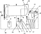
Accompanying drawing 3 is a structural representation of the present utility model,
Below in conjunction with drawings and Examples the utility model is elaborated,
The specific embodiment
Comprise content gauge 1, control cabinet 2, water tank 3, jack unit 4 among Fig. 3, it is characterized in that: the water inlet of water tank 3 is established backflow preventer 6 and control valve 7, join with tap water pipe network 14, delivery port is established air-stopping valve 8, link to each other with fire_fighting pipe network 9, be connected to jack unit 4 on the water tank 3, jack unit 4 is connected with the collection assembling device.It is characterized in that: the content gauge 1 that is connected water tank two ends about in the of 3 is provided with low liquid level control switch 10.It is characterized in that: the collection assembling device is linked to each other with jack unit 4 by high-flow pressure reducing valve 12, and high-flow pressure reducing valve 12 other ends are connected to the compression gas tank 5 of collection assembling device, and jack unit 4 is established flap valve 13 and control valve 15, links to each other with water tank 3.It is characterized in that: control cabinet 2 links to each other with air-stopping valve 8 with low liquid level control switch 10 and roof pressure valve 11 with pressure switch 17 by lead 16.It is characterized in that: compression gas tank 5 is by several and connect back access high-flow pressure reducing valve 12.
Equipment puts into operation, and the tap water pipe network is automatically to the water tank moisturizing, until being full of water tank.When the condition of a fire took place, jack unit was opened automatically, and the Compressed Gas in the compression gas tank 5 in the collection assembling device discharges, and water is headed into fire_fighting pipe network; When the drawdown in the water tank when minimum, the air-stopping valve action prevents that gas from flowing into fire_fighting pipe network.
Claims (5)
1. fire-fighting gas roof pressure water supply facilities, comprise content gauge, control cabinet, water tank, jack unit, it is characterized in that: the water inlet of water tank is established backflow preventer and control valve, join with the tap water pipe network, delivery port is established air-stopping valve, link to each other with fire_fighting pipe network, be connected to jack unit on the water tank, jack unit is connected with the collection assembling device.
2. by the described a kind of fire-fighting gas roof pressure water supply facilities of claim 1, it is characterized in that: be connected water tank up and down the content gauge at two ends low liquid level control switch is set.
3. by the described a kind of fire-fighting gas roof pressure water supply facilities of claim 1, it is characterized in that: the collection assembling device is linked to each other with jack unit by high-flow pressure reducing valve, the high-flow pressure reducing valve other end is connected to the compression gas tank of collection assembling device, and jack unit is established flap valve and control valve, links to each other with water tank.
4. by the described a kind of fire-fighting gas roof pressure water supply facilities of claim 1, it is characterized in that: control cabinet links to each other with air-stopping valve with liquid-level switch and roof pressure valve with pressure switch by lead.
5. by the described a kind of fire-fighting gas roof pressure water supply facilities of claim 3, it is characterized in that: compression gas tank is by several and connect back access high-flow pressure reducing valve.
Priority Applications (1)
| Application Number | Priority Date | Filing Date | Title |
|---|---|---|---|
| CN2010201356612U CN201730145U (en) | 2010-03-19 | 2010-03-19 | Top-pressure water supply equipment for fire fighting gas |
Applications Claiming Priority (1)
| Application Number | Priority Date | Filing Date | Title |
|---|---|---|---|
| CN2010201356612U CN201730145U (en) | 2010-03-19 | 2010-03-19 | Top-pressure water supply equipment for fire fighting gas |
Publications (1)
| Publication Number | Publication Date |
|---|---|
| CN201730145U true CN201730145U (en) | 2011-02-02 |
Family
ID=43521302
Family Applications (1)
| Application Number | Title | Priority Date | Filing Date |
|---|---|---|---|
| CN2010201356612U Expired - Fee Related CN201730145U (en) | 2010-03-19 | 2010-03-19 | Top-pressure water supply equipment for fire fighting gas |
Country Status (1)
| Country | Link |
|---|---|
| CN (1) | CN201730145U (en) |
Cited By (1)
| Publication number | Priority date | Publication date | Assignee | Title |
|---|---|---|---|---|
| CN102698906A (en) * | 2012-06-14 | 2012-10-03 | 广州市燊格喷涂设备有限公司 | Constant-pressure type anti-backflow fluid delivery system of spraying device |
-
2010
- 2010-03-19 CN CN2010201356612U patent/CN201730145U/en not_active Expired - Fee Related
Cited By (1)
| Publication number | Priority date | Publication date | Assignee | Title |
|---|---|---|---|---|
| CN102698906A (en) * | 2012-06-14 | 2012-10-03 | 广州市燊格喷涂设备有限公司 | Constant-pressure type anti-backflow fluid delivery system of spraying device |
Similar Documents
| Publication | Publication Date | Title |
|---|---|---|
| CN206488054U (en) | A kind of pressure release reflux for pump discharge | |
| CN206205056U (en) | A kind of non-negative pressure water service system | |
| CN209568506U (en) | A kind of two-way constant pressure water supply non-negative pressure water service system | |
| CN209412913U (en) | A kind of cavity-separating constant current constant voltage compensating tank and the supply equipment with the compensating tank | |
| CN202324069U (en) | Intelligent pipe network laminated pressure (zero negative pressure) stabilized-flow water supply equipment | |
| CN105780869A (en) | Electronic frequency-conversion constant-pressure water supply equipment and water supply method | |
| CN214094886U (en) | Constant pressure tank mode constant pressure water replenishing device | |
| CN201730145U (en) | Top-pressure water supply equipment for fire fighting gas | |
| CN100507167C (en) | Direct water-taking water tank pressurization and water supply equipment | |
| CN201416184Y (en) | Integral non-negative pressure water supply equipment | |
| CN102913753A (en) | Storage and gasification project output system of LNG (Liquefied Natural Gas) receiving terminal as well as method | |
| CN201024446Y (en) | Direct water-taking water tank pressurization and water supply equipment | |
| CN208280221U (en) | A kind of energy-saving compensated formula is without negative pressure pressure-superposed water supplying facility | |
| CN217756924U (en) | Water treatment equipment for integrated cold station and integrated cold station | |
| CN103104433A (en) | Large-discharge built-in automatic reversing hydraulic plunger pump | |
| CN207277418U (en) | A kind of new subregion intelligent water supply system and water supply installation | |
| CN202868303U (en) | Storage and gasification engineering output system of liquefied natural gas (LNG) accepting station | |
| CN211523366U (en) | Double-cavity non-negative pressure water supply equipment | |
| CN2853921Y (en) | Air-compensating water supply equipment | |
| CN210035813U (en) | Water system constant pressure water supplement protection device | |
| CN2786312Y (en) | Self-filling device of water pump | |
| CN212318239U (en) | High-pressure water mist pump set system for machine room | |
| CN205999980U (en) | A kind of laminating water supply equipment | |
| CN206174045U (en) | Frequency conversion deep -well pump | |
| CN111022227A (en) | Prevent fuel feeding system that evacuates |
Legal Events
| Date | Code | Title | Description |
|---|---|---|---|
| C14 | Grant of patent or utility model | ||
| GR01 | Patent grant | ||
| CF01 | Termination of patent right due to non-payment of annual fee |
Granted publication date: 20110202 Termination date: 20150319 |
|
| EXPY | Termination of patent right or utility model |