CN201710098U - Intelligent curtain with safety precaution alarm function - Google Patents
Intelligent curtain with safety precaution alarm function Download PDFInfo
- Publication number
- CN201710098U CN201710098U CN201020171058XU CN201020171058U CN201710098U CN 201710098 U CN201710098 U CN 201710098U CN 201020171058X U CN201020171058X U CN 201020171058XU CN 201020171058 U CN201020171058 U CN 201020171058U CN 201710098 U CN201710098 U CN 201710098U
- Authority
- CN
- China
- Prior art keywords
- circuit
- curtain
- connects
- connector
- relay
- Prior art date
- Legal status (The legal status is an assumption and is not a legal conclusion. Google has not performed a legal analysis and makes no representation as to the accuracy of the status listed.)
- Expired - Fee Related
Links
Images



Abstract
The utility model relates to an intelligent curtain with safety precaution alarm function, which adopts a master control board. The master control board comprises a microprocessor MCU which is arranged on an electric plate, wherein the microprocessor MCU is respectively and electrically connected with a remote control receiver, a clock circuit, a telephone on-line programming circuit, a curtain motor control circuit, a connector J5 and a connector J4 which are arranged on the same electric plate; the connector J5 is connected with a safety precaution alarm control board; the connector J4 is connected with an infrared processing circuit and a fuel gas induction circuit; the safety precaution alarm control board comprises an FLASH storage, a dialing and receiving processing circuit, an LCD display and a voice record playback circuit; and a signal tone detection circuit, a keyboard and a telephone interface circuit are connected with a plurality of interfaces of the microprocessor MCU. The curtain is controlled to open and close by a remote controller, has the functions of infrared human body monitoring and fuel gas leakage monitoring and is connected with a telephone network to alarm. The scheme with voice prompt and display monitoring functions overcomes the defect of single function of the existing electric curtain. The intelligent curtain is suitable for household installation.
Description
Technical field
The utility model relates to a kind of intelligent curtain with safety protection alarm function.
Background technology
At present, family expenses and office building, the curtain great majority that use in the hotel are manual directly foldings, the function of the curtain of the electronic control that has appeared on the market has only the open and close of beating of curtain to close, stop three moving control functions, just changeing, reverse, stopping of motor-driven curtain motor and realize opening, close and stopping of curtain, the control panel timer carry out timer counter, timer counter reaches the value of setting back is driven the curtain motor by control panel action; But the electrically driven curtain product has only curtain open/close, function singleness, the intelligent degree of the electric elements of employing and circuit design is low, and costs an arm and a leg, can't penetration and promotion when reality is used, and do not possess the security alarm function that the monitoring of human body infrared induction and indoor fuel gas are monitored.
Summary of the invention
At above-mentioned situation, it is a kind of simple for structure that the utility model provides, the reliability height, cost is low, the collection remote controller is controlled curtain open/close, is stopped, have the infrared induction monitoring and be connected realization security alarm function with the indoor fuel gas monitoring and with telephone network, have the intelligent curtain with safety protection alarm function of voice suggestion and display function.
For achieving the above object, a kind of intelligent curtain with safety protection alarm function, its master control borad comprises that the microprocessor MCU that is installed on the electroplax is electrically connected the remote-controlled receiver that is installed on the same electroplax respectively, clock circuit, phone online programming circuit, the curtain circuit for controlling motor, connector J5, connector J4, connector J5 connects the security alarm control panel, connector J4 connects infra red treatment circuit and combustion gas sensor circuit, the curtain circuit for controlling motor connects the curtain motor, and the machine control unit of curtain motor and curtain motor are encapsulated in the curtain open/close gear box; Described security alarm control panel comprises the FLASH holder that is installed on another electroplax, dial and the treatment circuit that collects the digits, LCD display, audio record circuit, and signal tone testing circuit, keyboard and telephone interface circuit are connected with several interfaces of microprocessor MCU; Telephone interface circuit is electrically connected dialing and collects the digits treatment circuit, LCD display, audio record circuit, public phone network telephone wire, signal tone testing circuit, and the public phone network telephone wire connects Local Exchange; Described curtain circuit for controlling motor comprises that ACL and ACN are respectively the live wire and the zero line of 220V alternating current, relay T5 connects positive adapter of curtain motor and triode Q8, relay T6 connects curtain motor counter-rotating joint and triode Q9, and the curtain circuit for controlling motor inserts P13 and the P14 port of microprocessor MCU; Described infra red treatment circuit comprises that infrared sensor connects heat and releases IC chip, and heat is released IC chip and connected filter circuit and triode Q15, connects the P33 port of microprocessor MCU through relay T8; Described combustion gas sensor circuit comprises that gas security connects triode Q5, connects relay T2 through connector J1, J2, and relay T2 connects the P35 port of microprocessor MCU; Described telephone interface circuit comprises that with the signal tone testing circuit contact of relay J P1 is connected telephone line interface and coupling transformer, and relay J P1 connects detection chip through triode Q1, and triode Q1 connects the P36 port of microprocessor MCU; Described dialing comprises that with the treatment circuit that collects the digits integrated circuit links to each other by the 2nd pin of peripheral amplifying circuit with audio frequency coupling transformer, and the binary data of the number of dialed number and reception passes through pin D3, D2, and D1, D0 is connected with the I/O port of microprocessor MCU.
In order to realize result optimizing, improve, improve combination property of the present utility model, further step is:
The model of described microprocessor MCU is the AT89S52 single-chip microcomputer.
Described infrared sensor model is RE200B, and it is BIS0001 that heat is released the IC chip model.
Described FLASH holder model is AT24C02.
Described detection chip model is CR6230.
Described integrated circuit model is MT8880.
Described LCD display model is LCD1602.
The voice recording and playback ic model of described audio record circuit is ISD1420.
Microprocessor in the described remote-controlled receiver dedicated radio link remote controller, remote controller is SMD encapsulation MCS89C2051 single-chip microcomputer.
The utility model adopts master control borad to comprise that the microprocessor MCU that is installed on the electroplax is electrically connected remote-controlled receiver, clock circuit, phone online programming circuit, curtain circuit for controlling motor, connector J5, the connector J4 that is installed on the same electroplax respectively, connector J5 connects the security alarm control panel, and connector J4 connects infra red treatment circuit and combustion gas sensor circuit; Described security alarm control panel comprises the FLASH holder that is installed on another electroplax, dial and the treatment circuit that collects the digits, LCD display, audio record circuit, and signal tone testing circuit, keyboard and telephone interface circuit are connected with several interfaces of microprocessor MCU; Telephone interface circuit is electrically connected dialing and collects the digits treatment circuit, LCD display, audio record circuit, public phone network telephone wire, signal tone testing circuit, the public phone network telephone wire connects Local Exchange, by remote controller control curtain open/close, have the infrared human body monitoring and be connected warning with the gas leakage monitoring function and with telephone network, scheme with voice suggestion and display monitoring function has overcome the defective of existing electrically driven curtain function singleness.
The beneficial effect that the utility model is produced compared to existing technology:
1, makes the functional diversities, integrated, intelligent of electrically driven curtain, good reliability.
2, bring the comfortableness of life staying idle at home, strengthened the security of life staying idle at home.
3, the moving curtain remote control of current collection has a power failure manually, the infrared induction monitoring, and indoor fuel gas carries out leak supervision in one.
4, make full use of public telephone and carry out dialing alarm.
5, adopt various chips and integrated circuit to make the volume of product little, function is many, and is simple to operate.
6, simple in structure, the reliability height, low cost of manufacture, good and cheap, good in economic efficiency.
The utility model is applicable to that family uses, and also is applicable to the use of office building and hotel.
Below in conjunction with the drawings and specific embodiments the utility model is described in further detail.
Description of drawings
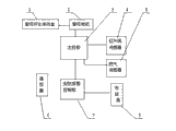
Fig. 1 is an overall structure Organization Chart of the present utility model.
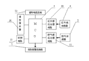
Fig. 2 is the circuit structure diagram of master control borad.
Fig. 3 is the circuit connection diagram of microprocessor MCU.
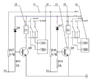
Fig. 4 is curtain circuit for controlling motor figure.
Fig. 5 is infrared induction treatment circuit figure.
Fig. 6 is combustion gas sensor circuit figure.
Fig. 7 is a security alarm control panel circuit structure diagram.
Fig. 8 is a serial FLASH holder circuit diagram.
Fig. 9 is telephone interface circuit and signal tone testing circuit figure.
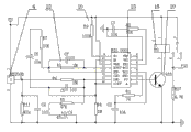
Figure 10 is dialing and the dtmf signal transmission circuit figure that collects the digits and handle.
Figure 11 is the utility model fundamental diagram.
Among the figure: 1, the curtain open/close gear box, 2, the curtain motor, 3, master control borad, 4, infrared ray sensor, 5, gas security, 6, remote controller, 7, the security alarm control panel, 8, Local Exchange, 9, microprocessor MCU, 10, the infra red treatment circuit, 11, the combustion gas sensor circuit, 12, the curtain circuit for controlling motor, 13, clock circuit, 14, remote-controlled receiver, 15, phone online programming circuit, 16, connector J5,17, connector J4,18, relay, 19, the positive adapter of curtain motor, 20, triode, 21, curtain motor counter-rotating joint, 22, filter circuit, 23, heat is released IC chip, and 24, the FLASH holder, 25, the dialing and the treatment circuit that collects the digits, 26, LCD display, 27, the public phone network telephone wire, 28, keyboard, 29, telephone interface circuit, 30, audio record circuit, 31, the signal tone testing circuit, 32, telephone line interface, 33, audio frequency coupling transformer, 34, detection chip, 35, integrated circuit.
The specific embodiment
Extremely shown in Figure 11 by accompanying drawing Fig. 1, a kind of intelligent curtain with safety protection alarm function, its master control borad 3 comprises that the microprocessor MCU9 that is installed on the electroplax is electrically connected the remote-controlled receiver 14 that is installed on the same electroplax respectively, clock circuit 13, phone online programming circuit 15, curtain circuit for controlling motor 12, connector J516, connector J417, connector J516 connects security alarm control panel 7, connector J417 connects infra red treatment circuit 10 and combustion gas sensor circuit 11, curtain circuit for controlling motor 12 connects curtain motor 2, and the machine control unit of curtain motor 2 and curtain motor 2 are encapsulated in the curtain open/close gear box 1; Security alarm control panel 7 comprises the FLASH holder 24 that is installed on another electroplax, dial and the treatment circuit 25 that collects the digits, LCD display 26, audio record circuit 30, and signal tone testing circuit 31, keyboard 28 and telephone interface circuit 29 are connected with several interfaces of microprocessor MCU9; Telephone interface circuit 29 is electrically connected dialing and collects the digits treatment circuit 25, LCD display 26, audio record circuit 30, public phone network telephone wire 27, signal tone testing circuit 31, and public phone network telephone wire 27 connects Local Exchange 8; Described curtain circuit for controlling motor 12 comprises that ACL and ACN are respectively the live wire and the zero line of 220V alternating current, relay 18T5 connects curtain motor 2 positive adapter 19 and triode 20Q8, relay 18T6 connects curtain motor 2 counter-rotating joint 21 and triode 20Q9, and curtain circuit for controlling motor 12 connects P13 and the P14 port of microprocessor MCU9; Infra red treatment circuit 10 comprises that infrared sensor 4 connects heat and releases IC chip 23, and heat is released IC chip 23 and connected filter circuit 22 and triode 20Q15, connects the P33 port of microprocessor MCU9 through relay 18T8; Combustion gas sensor circuit 11 comprises that gas security 5 connects triode 20Q5, connects relay 18T2 through connector J1, J2, and relay 18T2 connects the P35 port of microprocessor MCU9; Telephone interface circuit 29 comprises that with signal tone testing circuit 31 contact of relay 18JP1 is connected telephone line interface 32 and coupling transformer 33, and relay 18JP1 connects detection chip 34 through triode 20Q1, and triode 20Q1 connects the P36 port of microprocessor MCU9; Dialing comprises that with the treatment circuit 25 that collects the digits integrated circuit 35 links to each other by the 2nd pin of peripheral amplifying circuit with audio frequency coupling transformer 33, the binary data of the number of dialed number and reception is by pin D3, D2, D1, D0 is connected with the I/O port of microprocessor MCU9.
By Fig. 1, shown in Figure 2, Fig. 1 is the overall structure Organization Chart, Fig. 2 is the circuit structure diagram of master control borad 3, and master control borad 3 and security alarm control panel 7 are core with microcontroller MCU9 all, and microcontroller MCU9 adopts the AT89S52 single-chip microcomputer, this is a kind of low-power consumption, high performance 8 8-digit microcontroller MCU, embedded 8K Flash memory able to programme, the SMD encapsulation of the microcontroller MCU MCS89C2051 single-chip microcomputer in the curtain remote controller 6 is with the little and big requirement of function of volume of satisfying remote controller.
By shown in Figure 3, circuit connection diagram for microprocessor MCU9, the clock circuit 13, phone online programming circuit 15, receiver of remote-control sytem 6, connector J516, the connector J417 that on master control borad, microcontroller MCU9 are installed and are electrically connected with controller MCU9, connector J417 is used to receive the detection information by infrared sensor 4 and gas security 5 and treatment circuit transmission, and connector J516 is used for sending all kinds of alarm signals to security alarm control panel 7.
By shown in Figure 4, be the control circuit figure of curtain motor 2, in order to realize the electronic control of curtain, be curtain motor 2 but select the low speed ac synchronous motor of rotating for use, power by civil power 220V.Machine control unit and curtain motor 2 that curtain motor 2 rotates are encapsulated in the curtain open/close gear box 1, and size and position according to curtain during installation are provided with; ACL and ACN are respectively the live wire and the zero line of 220V alternating current, the positive adapter 19 of curtain motor connects the positive pole of curtain motor 2, and curtain motor counter-rotating joint 21 connects the negative pole of curtain motor 2, relay 18 T5 action, relay 18 T6 discharge, and then curtain motor 2 is just changeing; Relay 18T6 action, relay 18T5 discharge, then curtain motor 2 counter-rotatings; Relay 18 T5, T6 are failure to actuate, and then curtain motor 2 is motionless; Relay 18T5 and T6 are controlled by P13 and the P14 port of microcontroller MCU9 respectively, and level"1" is action, and level "0" is for discharging.
By shown in Figure 5, circuit diagram for infrared induction treatment circuit 10, according to the principle of human body to the infrared thermal releasing induction, heat is released the infrared signal that infrared sensor 4 goes out detected human body radiation and is converted to low frequency 0.5~9Hz signal of telecommunication, add to heat and release input 14 pin of the first order operational amplifier of IC chip 23, after the two poles of the earth amplification, filtering and signal are handled, the high-level control signal of certain time-delay is arranged in the output of its output VO2 pin; The base stage that this control signal adds to triode 20Q15 makes it conducting, thereby makes relay 18T8 action, sends the warning message that has the people to enter to the P33 of microcontroller MCU9 port; It is BISS0001 that heat is released IC chip 23 models, and heat is released infrared sensor 4 and adopted the RE200B sensor.
By shown in Figure 6, be combustion gas sensor circuit 11 figure, detect by gas security 5 whether gas leakage is arranged, if gas leakage is arranged, then the 4th pin output high level makes triode 20Q5 conducting, drive relay 18T2 adhesive by triode 20Q5 again, send the gas leakage alarm signal to the P35 of microcontroller MCU9 port by the normally opened contact of relay 18T2.
By shown in Figure 7, be security alarm control panel 12 circuit structure diagrams, FLASH memory 14, signal tone testing circuit 31 be installed on the control panel, dialling is connected with microcontroller MCU9 interface respectively with the treatment circuit 25 that collects the digits, audio record circuit 30, LCD display 26, telephone interface circuit 29.Audio record circuit 30 adopts the ISD1420 voice recording and playback ic, entire circuit is by voice recording and playback ic and peripheral circuit, reach interface circuit formation with microcontroller MCU9,20 seconds voice messagings of ISD1420 chip sectional storage, by readable 3 Chinese characters calculating each second, sectional was stored 600 phonetic Chinese characters in 20 seconds, can be divided into 160 sections at most; LCD display 26 is used for enquiry number, password and command code, LCD display 26 adopt LCD1602 capable * 16 characters, the character mode lcd module is the information display spare in the application system; It is little, low in energy consumption that LCD1602 has a volume, the characteristics that displaying contents is abundant, and the controller of Liquid Crystal Module inside has 11 control instructions, and the operation of its read-write operation, screen and cursor all can realize by microcontroller MCU9 instruction programming.
By shown in Figure 8, circuit diagram for serial FLASH memory 24, FLASH memory 24 be used for the prestoring phone number dialed when reporting to the police, office's base number, 110,119,120 and the password and the command code of household electrical appliances Long-distance Control, selecting capacity for use is the AT24C02 of 256 bytes.The AT24C02 chip is to have I
2The E2PROM memory of C EBI has the power-failure memory function, and its internal address space is 00H~ffH, and there are A2, A1, A0 three bit address in the outside, can connect 8 AT24C02 chips on the bus, I
2The C bus structures are very simple, have only two lines, comprise a data wire SDA and a serial time clock line SCL.Has I
2The device of C interface can be received on the bus by these two lines, carries out information transmission each other.Adopt I by I/O mouth P30 and P31 between AT24C02 chip and the microcontroller MCU9
2The C bus connects.
By shown in Figure 9, for the circuit diagram of telephone interface circuit 29, comprise the circuit for answering of phone and the coupling circuit of audio frequency coupling transformer 33 with signal tone testing circuit 31, audio frequency coupling transformer 33 is used for the coupling of signal tone, message voice, dtmf signal.Circuit for answering is realized with release by the adhesive of microcontroller MCU9 control relay 18JP1, when the P36 of microcontroller MCU9 port is sent high level, triode Q1 conducting, relay 18JP1 adhesive, the contact 7 of relay 18JP1 links to each other with outside line with 8, and constitutes the off-hook loop by elements such as R2, when the P36 of microcontroller MCU9 port is sent low level, then the off-hook loop disconnects, and is equivalent to come back to hook state.SIGN is the interface of audio frequency coupling transformer 33 and signal tone testing circuit 31 among the figure, and TONE is the interface of dual tone multi-frequency dtmf number transmission circuit, and SP+ and SP – are the interface of voice playing circuit.Signal tone testing circuit 31 is finished by signal tone dedicated test chip 34, and detection chip 34 models are CR6230, and the pin of its signal input SIGN links to each other with audio frequency coupling transformer 33, can accurately discern the various signal tones of telephone line, dialing tone, ring-back tone, busy tone, howler tone; By four pin outputs, be connected to the input port of microcontroller MCU9 respectively, microcontroller MCU9 only need read the state of each pin.
By shown in Figure 10, be the circuit diagram of dialing with the treatment circuit 25 that collects the digits, mainly finish the reception of dialing, transmission and Long-distance Control password and the command code operational order sign indicating number of telephone number, because number and signaling on the PSTN are all transmitted with the DTMF standard, adopt DTMF transmitting-receiving special IC 35 among the figure, model is MT8880, and the input IN of the dtmf signal of this MT8880, output TONE are by peripheral amplifying circuit
WithThe 2nd pin of audio frequency coupling transformer 33 links to each other, the binary data of the number of dialed number and reception is by pin D3, D2, D1, D0 links to each other with the I/O port of microcontroller MCU9, thereby the dtmf signal of dialed number uploads to telephone line, and far-end is transported to dtmf signal on the telephone line and also is decoded into number and is read by microcontroller MCU9.
The folding of curtain motor 2 control curtain, the work control of curtain motor 2 possesses following three kinds of modes:
1, uses a teleswitch and 6 handle, during instruction key on pressing remote controller 6, remote-controlled receiver 14 received signals, and transmit signals to microcontroller MCU9, microcontroller MCU9 is sent to curtain circuit for controlling motor 12 after signal is handled, when by " closing " key on the remote controller 6, curtain motor 2 work of just changing a job, curtain is pulled and closes; During by " stopping " key, curtain motor 2 quits work; The curtain stop motion; During by " opening " key, the 2 counter-rotating work of curtain motor, curtain is drawn back, and reaches head always, in curtain 2 motions, no matter draws back or closes, and curtain motor 2 all can stop motion during by " stopping " key.
2, timing switching curtain, press the numerical key of the instruction key on the remote controller 6, remote-controlled receiver 14 received signals, and transmit signals to microcontroller MCU9, microcontroller MCU9 starts clock circuit 13, the instruction keyboard of remote controller 6 has the 1-9 key, imports one and determines number, and the clock circuit 13 that is connected with microcontroller MCU9 will be noted this number, when the time extends to this time, microcontroller MCU9 passes the signal to curtain circuit for controlling motor 12, and 2 work of curtain motor realize curtain open/close; By " cancellation " key, above-mentioned automatic cancellation is set, by " removings " key, 2 rotations of curtain motor are forced to stop, and the timing that is provided with is previously opened or regularly closed and will be eliminated, and is if repeatedly be provided with, effective for the last time.Microprocessor in the remote controller 6 is SMD encapsulation MCS89C2051 single-chip microcomputer.
3, infrared induction and from the moving control automatically of combustion gas induction with report to the police, infrared sensor 4 is installed in the indoor place that enters, in the time of in people's inlet chamber, infrared sensor 4 detects the signal in people's inlet chamber, and after infrared induction treatment circuit 10 is handled, sending this signal to microcontroller MCU9, microcontroller MCU9 is sent to curtain circuit for controlling motor 12 after signal is handled again, make 2 work of curtain motor, open curtain automatically; When in the kitchen gas leakage being arranged, combustion gas inductor 5 has detected the gas leakage signal, and after handling, combustion gas sensor circuit 11 sends this signal to microcontroller MCU9, after microcontroller MCU9 handles signal again, be sent to curtain circuit for controlling motor 12, make 2 work of curtain motor, open curtain automatically; Simultaneously if when having the people to be in, signal after microcontroller MCU9 will handle again, be sent to audio record circuit 30, providing voice suggestion is handled to remind owner, if during nobody home, signal after microcontroller MCU9 will handle again, be sent to dialing and collect the digits treatment circuit 25, and the public phone network telephone wire 27 that is dynamically connected certainly, start autodialer, transfer to 5 telephone numbers that prestored successively, and repeat 4 times, start audio record circuit 30 simultaneously, the callee of off-hook is play the voice that address and request are handled.The called people of arbitrary off-hook can cancel remaining dialing alarm by particular key, and * key or # key are set to particular key.
Claims (9)
1. intelligent curtain with safety protection alarm function, the master control borad (3) that it is characterized in that it comprises the microprocessor MCU(9 that is installed on the electroplax) be electrically connected the remote-controlled receiver (14) be installed on the same electroplax respectively, clock circuit (13), phone online programming circuit (15), curtain circuit for controlling motor (12), connector J5(16), connector J4(17), connector J5(16) connects security alarm control panel (7), connector J4(17) connects infra red treatment circuit (10) and combustion gas sensor circuit (11), curtain circuit for controlling motor (12) connects curtain motor (2), and the machine control unit of curtain motor (2) and curtain motor (2) are encapsulated in the curtain open/close gear box (1); Described security alarm control panel (7) comprises the FLASH holder (24) that is installed on another electroplax, dial and the treatment circuit that collects the digits (25), LCD display (26), audio record circuit (30) signal tone testing circuit (31), keyboard (28) and telephone interface circuit (29) and microprocessor MCU(9) several interfaces be connected; Telephone interface circuit (29) is electrically connected dialing and collects the digits treatment circuit (25), LCD display (26), audio record circuit (30), public phone network telephone wire (27), signal tone testing circuit (31), and public phone network telephone wire (27) connects Local Exchange (8); Described curtain circuit for controlling motor (12) comprises that ACL and ACN are respectively the live wire and the zero line of 220V alternating current, relay (18) T5 connects positive adapter (19) of curtain motor (2) and triode (20) Q8, relay (18) T6 connects curtain motor (2) counter-rotating joint (21) and triode (20) Q9, curtain circuit for controlling motor (12) connection microprocessor MCU(9) P13 and P14 port; Described infra red treatment circuit (10) comprises that infrared sensor (4) connects heat and releases IC chip (23), heat is released IC chip (23) and is connected filter circuit (22) and triode (20) Q15, through relay (18) T8 connection microprocessor MCU(9) the P33 port; Described combustion gas sensor circuit (11) comprises that gas security (5) connects triode (20) Q5, connects relay (18) T2 through connector J1, J2, and relay (18) T2 connects microprocessor MCU(9) the P35 port; Described telephone interface circuit (29) comprises that with signal tone testing circuit (31) relay (18) JP1 contact is connected telephone line interface (32) and audio frequency coupling transformer (33), relay (18) JP1 connects detection chip (34) through triode (20) Q1, and triode (20) Q1 connects microprocessor MCU(9) the P36 port; Described dialing comprises that with the treatment circuit that collects the digits (25) integrated circuit (35) links to each other by the 2nd pin of peripheral amplifying circuit with coupling transformer (33), the binary data of dialed number and receiving number is by pin D3, D2, D1, D0 and microprocessor MCU(9) the I/O port be connected.
2. a kind of intelligent curtain with safety protection alarm function according to claim 1 is characterized in that described microprocessor MCU(9) model be the AT89S52 single-chip microcomputer.
3. a kind of intelligent curtain with safety protection alarm function according to claim 1 is characterized in that described infrared sensor (4) model is RE200B, and it is BIS0001 that heat is released IC chip (23) model.
4. a kind of intelligent curtain with safety protection alarm function according to claim 1 is characterized in that described FLASH holder (24) model is AT24C02.
5. a kind of intelligent curtain with safety protection alarm function according to claim 1 is characterized in that described detection chip (34) model is CR6230.
6. a kind of intelligent curtain with safety protection alarm function according to claim 1 is characterized in that described integrated circuit (35) model is MT8880.
7. a kind of intelligent curtain with safety protection alarm function according to claim 1 is characterized in that described LCD display (26) model is LCD1602.
8. a kind of intelligent curtain with safety protection alarm function according to claim 1, the voice recording and playback ic model that it is characterized in that described audio record circuit (30) is ISD1420.
9. a kind of intelligent curtain according to claim 1 with safety protection alarm function, it is characterized in that described remote-controlled receiver (14) dedicated radio link remote controller (6), the microprocessor in the remote controller (6) is SMD encapsulation MCS89C2051 single-chip microcomputer.
Priority Applications (1)
| Application Number | Priority Date | Filing Date | Title |
|---|---|---|---|
| CN201020171058XU CN201710098U (en) | 2010-04-27 | 2010-04-27 | Intelligent curtain with safety precaution alarm function |
Applications Claiming Priority (1)
| Application Number | Priority Date | Filing Date | Title |
|---|---|---|---|
| CN201020171058XU CN201710098U (en) | 2010-04-27 | 2010-04-27 | Intelligent curtain with safety precaution alarm function |
Publications (1)
| Publication Number | Publication Date |
|---|---|
| CN201710098U true CN201710098U (en) | 2011-01-19 |
Family
ID=43456090
Family Applications (1)
| Application Number | Title | Priority Date | Filing Date |
|---|---|---|---|
| CN201020171058XU Expired - Fee Related CN201710098U (en) | 2010-04-27 | 2010-04-27 | Intelligent curtain with safety precaution alarm function |
Country Status (1)
| Country | Link |
|---|---|
| CN (1) | CN201710098U (en) |
Cited By (6)
| Publication number | Priority date | Publication date | Assignee | Title |
|---|---|---|---|---|
| CN101803852A (en) * | 2010-04-27 | 2010-08-18 | 湖南科技大学 | Intelligent curtain with safety protection alarm function |
| CN103593930A (en) * | 2012-08-17 | 2014-02-19 | 成都众山科技有限公司 | Voice antitheft alarm system based on low-voltage general integration power amplifier |
| CN103593931A (en) * | 2012-08-17 | 2014-02-19 | 成都众山科技有限公司 | Household voice antitheft alarm system |
| CN104504835A (en) * | 2014-12-22 | 2015-04-08 | 芜湖市晨韵自动化科技有限公司 | Anti-theft curtain and control method thereof |
| CN104643875A (en) * | 2014-06-13 | 2015-05-27 | 阮树成 | Solar sunlight infrared double control three-phase micro motor double track opposite-opening curtain |
| CN108143238A (en) * | 2017-12-25 | 2018-06-12 | 钟建筑 | A kind of energy-conserving intelligent curtain |
-
2010
- 2010-04-27 CN CN201020171058XU patent/CN201710098U/en not_active Expired - Fee Related
Cited By (7)
| Publication number | Priority date | Publication date | Assignee | Title |
|---|---|---|---|---|
| CN101803852A (en) * | 2010-04-27 | 2010-08-18 | 湖南科技大学 | Intelligent curtain with safety protection alarm function |
| CN103593930A (en) * | 2012-08-17 | 2014-02-19 | 成都众山科技有限公司 | Voice antitheft alarm system based on low-voltage general integration power amplifier |
| CN103593931A (en) * | 2012-08-17 | 2014-02-19 | 成都众山科技有限公司 | Household voice antitheft alarm system |
| CN104643875A (en) * | 2014-06-13 | 2015-05-27 | 阮树成 | Solar sunlight infrared double control three-phase micro motor double track opposite-opening curtain |
| CN104643875B (en) * | 2014-06-13 | 2017-04-19 | 阮树成 | Solar sunlight infrared double control three-phase micro motor double track opposite-opening curtain |
| CN104504835A (en) * | 2014-12-22 | 2015-04-08 | 芜湖市晨韵自动化科技有限公司 | Anti-theft curtain and control method thereof |
| CN108143238A (en) * | 2017-12-25 | 2018-06-12 | 钟建筑 | A kind of energy-conserving intelligent curtain |
Similar Documents
| Publication | Publication Date | Title |
|---|---|---|
| CN101803852B (en) | Intelligent curtain with safety protection alarm function | |
| CN201710098U (en) | Intelligent curtain with safety precaution alarm function | |
| CN102510477B (en) | Digital indoor unit and intelligent household security system | |
| CN102207307B (en) | Intelligent controller of heating system network | |
| CN203259864U (en) | Remote smart home system | |
| CN205301847U (en) | Intelligent household system based on internet of things | |
| CN202563624U (en) | Intelligent alarm | |
| CN100583933C (en) | Remote control and warning apparatus for telephone | |
| CN103472801B (en) | Remote household bodyguard system and family bodyguard device | |
| CN205901936U (en) | Household security electronic monitoring system | |
| CN1865785A (en) | Intelligent control system for construction heating device and electrical equipment device | |
| CN101706113A (en) | Intelligent gas cooker | |
| CN202587141U (en) | Device for controlling household appliance remotely by telephone | |
| CN101998685A (en) | GPRS based wireless smart home system | |
| CN111538300A (en) | Intelligent home remote control system based on telephone network and control method thereof | |
| CN2911823Y (en) | Host and sub-device of remote smart controlled/monitored alarmer | |
| CN203241778U (en) | A household electrical appliance remote control apparatus | |
| CN215679477U (en) | Intelligent door lock device for controlling power cut and power transmission of room through Bluetooth transmission signal | |
| CN214174885U (en) | Intelligent visual voice central control system | |
| CN103745555A (en) | Automatic alarm system for carbon dioxide based on single-chip microcomputer and method thereof | |
| CN201213282Y (en) | Remote control and alarm apparatus for telephone | |
| CN2487170Y (en) | Intelligent controller for house | |
| CN2553412Y (en) | Intelligent control meter for radiator | |
| CN201491029U (en) | Household intelligent gateway | |
| CN208572204U (en) | SCM Based telephone remote control system |
Legal Events
| Date | Code | Title | Description |
|---|---|---|---|
| C14 | Grant of patent or utility model | ||
| GR01 | Patent grant | ||
| C17 | Cessation of patent right | ||
| CF01 | Termination of patent right due to non-payment of annual fee |
Granted publication date: 20110119 Termination date: 20130427 |