CN201704031U - Built-in anti-seizing side roller of forklift truck - Google Patents
Built-in anti-seizing side roller of forklift truck Download PDFInfo
- Publication number
- CN201704031U CN201704031U CN2010201649717U CN201020164971U CN201704031U CN 201704031 U CN201704031 U CN 201704031U CN 2010201649717 U CN2010201649717 U CN 2010201649717U CN 201020164971 U CN201020164971 U CN 201020164971U CN 201704031 U CN201704031 U CN 201704031U
- Authority
- CN
- China
- Prior art keywords
- side roller
- rollway
- nest
- built
- side wheel
- Prior art date
- Legal status (The legal status is an assumption and is not a legal conclusion. Google has not performed a legal analysis and makes no representation as to the accuracy of the status listed.)
- Expired - Fee Related
Links
Images
Abstract
The utility model relates to a built-in anti-seizing side roller of a forklift truck, comprising a side roller bracket, a side roller and a side roller shaft, and the side roller is mounted on the side roller frame through the side roller shaft. The built-in anti-seizing side roller of a forklift truck is characterized in that rollway nests are milled at two end faces of the side roller; and a sleeve ring comprising a washer with a rollway nest, a steel ball and a retaining frame component is embedded between the rollway nest and the side roller bracket. The built-in side roller of a forklift truck hast he advantages of bearing an axial force through arranging the rollway nest at two end faces of the side roller and embedding the sleeve ring which is arranged between the rollway nest and the side roller bracket and comprises the washer with a rollway nest, the steel ball and the retaining frame component so that the sleeve ring and the end face rollway nest of the side roller form a thrust ball bearing; greatly reducing friction coefficient as the sleeve ring and the end face of the side roller are in rolling friction instead of sliding friction of the conventional structure when the side roller receives axial pressure, avoiding the seizing phenomenon caused by the rapid abrasion of the side roller and the side roller bracket, and prolonging the service life.
Description
Technical field
The utility model relates to a kind of bearing, particularly a kind of built-in anti-blocking side roller wheel of forklift.
Background technology
The built-in side wheel of traditional fork truck comprises support, side wheel and axle, side wheel by axle mounting on support.Its shortcoming is: the side wheel of fork truck in use owing to be subjected to axial force, forms cliding friction between side wheel end face and the support, easily causes stuck phenomenon after the support wearing and tearing, and service life is short.
The utility model content
The technical problems to be solved in the utility model provides a kind of built-in anti-blocking side roller wheel of forklift, makes not produce friction between side wheel and the support, avoids stuck.
For solving the problems of the technologies described above, the technical solution of the utility model is: a kind of built-in anti-blocking side roller wheel of forklift, comprise side wheel support, side wheel and sidewinder wheel shaft, this side wheel passes through the side wheel axle mounting on the side wheel support, its innovative point is: the both ends of the surface of described side wheel are processed with a ring raceway, and are embedded with between this raceway and side wheel support by the packing ring of band raceway and the lasso that steel ball, retainer assembly constitute.
Advantage of the present utility model is: by in the side wheel both ends of the surface raceway being set, and between raceway and side wheel support, be embedded with by the packing ring of band raceway and the lasso that steel ball, retainer assembly constitute, the end face raceway of lasso and side wheel constitutes a thrust ball bearing, makes it can bear axial force.When side wheel is received axle pressure, be friction of rolling between lasso and the side wheel end face, and the cliding friction of non-traditional structure greatly reduce friction coefficient, the stuck phenomenon of avoiding side wheel and side wheel support to wear and tear and cause has fast improved service life.
Description of drawings
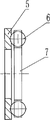
Fig. 1 is the utility model built-in anti-blocking side roller wheel of forklift structural representation.
Fig. 2 is the utility model ferrule arrangement scheme drawing.
The specific embodiment
As shown in Figure 1, 2, comprise side wheel support 1, side wheel 2, sidewinder wheel shaft 3, lasso 4, packing ring 5, steel ball 6, retainer 7.
Above-mentioned side wheel 2 is installed on the side wheel support 1 by sidewindering wheel shaft 3, and two ends of side wheel 2 have the cavity that caves in, and the cavity end face is processed with a ring raceway.Lasso 4 is made of packing ring 5, steel ball 6 and retainer 7 assemblies, and it is embedded between the cavity and side wheel support 1 of side wheel 2 end faces, makes the lasso 4 and one of the end face raceway formation of side wheel 2 be built in the thrust ball bearing that side wheel support 1 can bear axial force.
Claims (1)
1. built-in anti-blocking side roller wheel of forklift, comprise side wheel support, side wheel and sidewinder wheel shaft, this side wheel passes through the side wheel axle mounting on the side wheel support, it is characterized in that: the both ends of the surface of described side wheel are processed with a ring raceway, and are embedded with between this raceway and side wheel support by the packing ring of band raceway and the lasso that steel ball, retainer assembly constitute.
Priority Applications (1)
| Application Number | Priority Date | Filing Date | Title |
|---|---|---|---|
| CN2010201649717U CN201704031U (en) | 2010-04-21 | 2010-04-21 | Built-in anti-seizing side roller of forklift truck |
Applications Claiming Priority (1)
| Application Number | Priority Date | Filing Date | Title |
|---|---|---|---|
| CN2010201649717U CN201704031U (en) | 2010-04-21 | 2010-04-21 | Built-in anti-seizing side roller of forklift truck |
Publications (1)
| Publication Number | Publication Date |
|---|---|
| CN201704031U true CN201704031U (en) | 2011-01-12 |
Family
ID=43441187
Family Applications (1)
| Application Number | Title | Priority Date | Filing Date |
|---|---|---|---|
| CN2010201649717U Expired - Fee Related CN201704031U (en) | 2010-04-21 | 2010-04-21 | Built-in anti-seizing side roller of forklift truck |
Country Status (1)
| Country | Link |
|---|---|
| CN (1) | CN201704031U (en) |
Cited By (2)
| Publication number | Priority date | Publication date | Assignee | Title |
|---|---|---|---|---|
| CN101804954A (en) * | 2010-04-21 | 2010-08-18 | 如皋市非标轴承有限公司 | Built-in anti-blocking side roller wheel of forklift |
| CN103486132A (en) * | 2013-10-23 | 2014-01-01 | 江苏万达特种轴承有限公司 | Side rolling wheel assembly |
-
2010
- 2010-04-21 CN CN2010201649717U patent/CN201704031U/en not_active Expired - Fee Related
Cited By (2)
| Publication number | Priority date | Publication date | Assignee | Title |
|---|---|---|---|---|
| CN101804954A (en) * | 2010-04-21 | 2010-08-18 | 如皋市非标轴承有限公司 | Built-in anti-blocking side roller wheel of forklift |
| CN103486132A (en) * | 2013-10-23 | 2014-01-01 | 江苏万达特种轴承有限公司 | Side rolling wheel assembly |
Similar Documents
| Publication | Publication Date | Title |
|---|---|---|
| CN201133422Y (en) | Bearing clearance automatic regulating apparatus | |
| CN203214584U (en) | Guide rail-roller bearing | |
| CN201704031U (en) | Built-in anti-seizing side roller of forklift truck | |
| CN202091427U (en) | Bearing roller chain | |
| CN101799040A (en) | Self-pretightening double-row tapered roller bearing | |
| CN201034116Y (en) | Conical roller bearing with center-regulation ring | |
| CN101804954A (en) | Built-in anti-blocking side roller wheel of forklift | |
| CN203756727U (en) | Wear-resisting bearing | |
| CN201037506Y (en) | Double-row column roller bearing for rolling mill | |
| CN203272436U (en) | Tilting-installation roller bearing | |
| CN102478056A (en) | Bidirectional thrust conical roller bearing | |
| CN203395010U (en) | Spherical roller bearing with open elastic snap rings | |
| CN202579279U (en) | Device for combining horizontal type multi-stage pump rolling bearing | |
| CN202215584U (en) | Full-complement cylinder roller bearing | |
| CN201815545U (en) | Four-row tapered roller bearing without spacer | |
| CN201747771U (en) | Double-row full-complement cylindrical roller ferrule bearing | |
| CN202790085U (en) | Bidirectional thrust self-aligning roller bearing | |
| CN201925326U (en) | Bearing for crankshaft of motorcycle | |
| CN202833928U (en) | Automotive differential assembly | |
| CN202215578U (en) | Roller assembly | |
| CN204061544U (en) | A kind ofly can bear the automobile hub bearing of larger axis to active force | |
| CN203098559U (en) | Composite roller bearing | |
| CN202080860U (en) | Anti-jamming side roller of large-tonnage forklift | |
| CN201777846U (en) | Side roller assembly for forklift mast | |
| CN202690745U (en) | Combination type bearing |
Legal Events
| Date | Code | Title | Description |
|---|---|---|---|
| C14 | Grant of patent or utility model | ||
| GR01 | Patent grant | ||
| C17 | Cessation of patent right | ||
| CF01 | Termination of patent right due to non-payment of annual fee |
Granted publication date: 20110112 Termination date: 20130421 |