CN201670746U - Float-type oil collecting device - Google Patents
Float-type oil collecting device Download PDFInfo
- Publication number
- CN201670746U CN201670746U CN2010201382528U CN201020138252U CN201670746U CN 201670746 U CN201670746 U CN 201670746U CN 2010201382528 U CN2010201382528 U CN 2010201382528U CN 201020138252 U CN201020138252 U CN 201020138252U CN 201670746 U CN201670746 U CN 201670746U
- Authority
- CN
- China
- Prior art keywords
- oil
- fixed
- feed tank
- floating drum
- buoy
- Prior art date
- Legal status (The legal status is an assumption and is not a legal conclusion. Google has not performed a legal analysis and makes no representation as to the accuracy of the status listed.)
- Expired - Lifetime
Links
Images

Abstract
The utility model discloses a float-type oil collecting device which is applied to surface crude oil recovery in an oil field oil extraction sewage pool and mainly comprises a buoy, an adjusting rope, rotating arms, a fixed leg, an adjusting handle and an oil absorption hose, wherein the centers of two ends of the cylindrical buoy are connected with the rotating arms through shafts; the other end of the rotating arm is connected with a fixed link; the outer wall of the lower part of the buoy is fixed with an oil inlet groove which is a rectangular groove formed by welding steel plates; the upper part of the oil inlet groove is provided with a rectangular oil inlet, and the lower part thereof is provided with an oil outlet; the oil outlet is connected with the oil absorption hose; the other end of the oil absorption hose is connected with an oil-well pump; and the upper part of the buoy is fixed with the fixed link which is connected with the adjusting rope. The device has the benefits that the oil inlet of the oil inlet groove in the buoy is positioned in the oil layer, less water and more oil can enter, the oil collection efficiency is improved, and the post process cost is reduced. The device can recover the floating oil with the thickness of the oil layer being larger than 1mm on the liquid surface of a sewage pit or a sump oil pit.
Description
Technical field
Even the utility model relates to oil recovery field, oil field, particularly the surperficial crude oil recovery in the oil extraction-generated waste water pond is a kind of retrieving arrangement that is used for liquid-covered crude oil in contaminated-oil basin, the sewage lagoon.
Background technology
Store crude oil and water in the contaminated-oil basin in oil field or sewage lagoon, generally based on the composition of water, water is in the bottom in pond, and oil float is on the surface of water.Crude oil thickness does not wait from several millimeters to several centimetres.Consider that from the angle of environment protection or crude oil recovery fluid surface crude oil need reclaim in contaminated-oil basin or the sewage lagoon.
Traditional crude oil recovery process generally is the fluid surface that will receive the suction mouth of pipe insertion contaminated-oil basin of oil pump, and the oil pump of startup receipts then connects oil and is with water to extract out together, enters oily-water seperating equipment and carries out separating treatment.Suck the bad control of the depth that the mouth of pipe inserts, cause extracting out the bad control of hair oil water ratio.This method is difficult to be suitable for for volume bigger contaminated-oil basin or sewage lagoon, and it is not thorough not only to receive oil, and because the hypervolia that sucks has increased the post-processed expense.
The utility model content
The purpose of this utility model is: a kind of Float cylinder type oil-collecting device is provided, large-scale contaminated-oil basin or sewage lagoon mesexine crude oil are reclaimed, adopt the outer fixedly oil suction chamber of floating drum, the suction port of guaranteeing oil suction chamber in the crude oil recovery process in oil reservoir, oil suction as much as possible, the few suction.
The technical solution adopted in the utility model is: the Float cylinder type oil-collecting device, mainly form by floating drum, adjusting rope, swivel arm, fixed leg, adjusting handle and oil suction flexible pipe, it is characterized in that: the center, two ends at cylindrical floating drum is connected with swivel arm by axle, and the other end of swivel arm is connected with fixed link.Can be fixed on fixed leg the edge of oil sump, floating drum is put into oil sump, and floating drum can swim in the fluid surface in the oil sump, and floats with the height of liquid level.Be fixed with oil-feed tank on the outer wall of the bottom of floating drum, oil-feed tank is the rectangular slot that is welded into by steel plate, and rectangular oil-in is arranged at the top of oil-feed tank, and oil outlet is arranged at the bottom of oil-feed tank, and oil outlet connects the oil suction flexible pipe.The other end of oil suction flexible pipe connects oil well pump.Top at floating drum is fixed with fixed link, fixed link connects regulates rope, rope is regulated in pulling can make floating drum rotate, regulate the height of oil-in on the oil-feed tank, the height of oil-in is in oil reservoir the time, start the oil well pump on oil sump bank, the oil-in that crude oil enters by oil-feed tank is inhaled into oil-feed tank, and is drawn out of oil sump by the oil suction flexible pipe.Water can not enter oil-feed tank.
In order to increase the length of oil-feed tank oil-in, the length of described oil-feed tank is identical with the length of floating drum.
For the ease of operation, the adjusting handle is a direct rod shape, and an end of regulating handle is connected with the axle at scale card center, and the adjusting rope is fixed on to be regulated on the handle.Rotate and regulate handle stretchy adjusting rope, and can reflect the floating drum rotational angle, be i.e. the oil-in height of oil-feed tank.
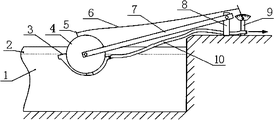
Float cylinder type oil-collecting device principle: consult Fig. 1.After the Float cylinder type oil-collecting device was installed, because that floating drum 4 front ends are fixed with oil-feed tank 3 is heavier, the oil-in position of oil-feed tank 3 may be positioned at water layer 1.Consult Fig. 2.Pulling is regulated 9, by the traction of adjusting rope 6, and floating drum 4 rotational angles, the oil-in of oil-feed tank 3 rises in the oil reservoir 2.Start the ground oil well pump, surperficial crude oil is pumped to ground.
The beneficial effects of the utility model: the utility model Float cylinder type oil-collecting device; the oil-in position of guaranteeing oil-feed tank on the floating drum is positioned at oil reservoir, enters water less and enters oil more, improves and receives oily efficient; reduce the post-processed expense, and be of value to the raising of environment protection and production efficiency.Can reclaim in sump or the sump oil hole fluid surface core intersection greater than 1 centimetre oil slick.
Description of drawings
Fig. 1 is the utility model Float cylinder type oil-collecting device scheme of installation.
Fig. 2 is the utility model Float cylinder type oil-collecting device regulate process synoptic diagram.
Among the figure, 1. water layer, 2. oil reservoir, 3. oil suction chamber, 4. floating drum, 5. fixed link is 6. regulated rope, 7. swivel arm, 8. fixed leg is 9. regulated handle, 10. oil suction flexible pipe.
Embodiment
Embodiment 1: with a Float cylinder type oil-collecting device is example, and the utility model is described in further detail.
Consult Fig. 1.The utility model Float cylinder type oil-collecting device mainly is made up of floating drum 4, adjusting rope 6, swivel arm 7, fixed leg 8, adjusting handle 9 and oil suction flexible pipe 10.
Cylindrical floating drum 4 has thin stainless steel plate to be welded into, 300 millimeters of external diameters, 2000 millimeters of length.Be welded with an axle respectively at the center, two ends of cylindrical floating drum 4, be connected with the swivel arm 7 that the rectangle steel plate is made by axle, the axle on the other end of swivel arm 7 and the fixed link 5 is connected.Swivel arm 7 and floating drum 4 can both rotate.Fixed leg 8 is fixed on the edge of oil sump.On the outer wall of the bottom of floating drum 4, be welded with oil-feed tank 3,2000 millimeters of the length of oil-feed tank 3.Oil-feed tank 3 is the rectangular slots that are welded into by steel plate, and rectangular oil-in is arranged at the top of oil-feed tank 3,2000 millimeters of the length of oil-in, 20 millimeters of width.A circular oil outlet is arranged at the bottom of oil-feed tank 3, and oil outlet connects an oil suction flexible pipe 10.The other end of oil suction flexible pipe 10 connects oil well pump.Be welded with a fixed link 5 on the top of floating drum 4, fixed link 5 connects one and regulates rope 6.The other end of regulating rope 6 connects regulates handle 9.Regulating handle 9 is direct rod shape, and an end of regulating handle 9 is connected with the axle at scale card center.Scale card is fixed on the edge of oil sump.2500 millimeters of the width of oil sump.
Claims (3)
1. Float cylinder type oil-collecting device, mainly by floating drum (4), regulate rope (6), swivel arm (7), fixed leg (8), regulating handle (9) and oil suction flexible pipe (10) forms, it is characterized in that: the center, two ends at cylindrical floating drum (4) is connected with swivel arm (7) by axle, the other end of swivel arm (7) is connected with fixed link (5), on the bottom outer wall of floating drum (4), be fixed with oil-feed tank (3), oil-feed tank (3) is the rectangular slot that is welded into by steel plate, rectangular oil-in is arranged at the top of oil-feed tank (3), oil outlet is arranged at the bottom of oil-feed tank (3), oil outlet connects oil suction flexible pipe (10), the other end of oil suction flexible pipe (10) connects oil well pump, be fixed with fixed link (5) on the top of floating drum (4), fixed link (5) connects regulates rope (6).
2. Float cylinder type oil-collecting device according to claim 1 is characterized in that: the length of described oil-feed tank (3) is identical with the length of floating drum (4).
3. Float cylinder type oil-collecting device according to claim 1 is characterized in that: regulating handle (9) is direct rod shape, and an end of regulating handle (9) is connected with the axle at scale card center, and adjusting rope (6) is fixed on to be regulated on the handle (9).
Priority Applications (1)
| Application Number | Priority Date | Filing Date | Title |
|---|---|---|---|
| CN2010201382528U CN201670746U (en) | 2010-03-19 | 2010-03-19 | Float-type oil collecting device |
Applications Claiming Priority (1)
| Application Number | Priority Date | Filing Date | Title |
|---|---|---|---|
| CN2010201382528U CN201670746U (en) | 2010-03-19 | 2010-03-19 | Float-type oil collecting device |
Publications (1)
| Publication Number | Publication Date |
|---|---|
| CN201670746U true CN201670746U (en) | 2010-12-15 |
Family
ID=43328158
Family Applications (1)
| Application Number | Title | Priority Date | Filing Date |
|---|---|---|---|
| CN2010201382528U Expired - Lifetime CN201670746U (en) | 2010-03-19 | 2010-03-19 | Float-type oil collecting device |
Country Status (1)
| Country | Link |
|---|---|
| CN (1) | CN201670746U (en) |
Cited By (4)
| Publication number | Priority date | Publication date | Assignee | Title |
|---|---|---|---|---|
| CN102583645A (en) * | 2012-03-28 | 2012-07-18 | 西南铝业(集团)有限责任公司 | Floating oil absorbing device |
| CN105753097A (en) * | 2014-12-16 | 2016-07-13 | 镇江润京机电科技有限公司 | Unpowered automatic oil trapping device |
| CN108996607A (en) * | 2018-08-21 | 2018-12-14 | 胡自然 | A kind of coal chemical wastewater treating technique |
| CN110013687A (en) * | 2018-01-09 | 2019-07-16 | 中国石油化工股份有限公司 | Centrifugal grease adsorption separating method |
-
2010
- 2010-03-19 CN CN2010201382528U patent/CN201670746U/en not_active Expired - Lifetime
Cited By (4)
| Publication number | Priority date | Publication date | Assignee | Title |
|---|---|---|---|---|
| CN102583645A (en) * | 2012-03-28 | 2012-07-18 | 西南铝业(集团)有限责任公司 | Floating oil absorbing device |
| CN105753097A (en) * | 2014-12-16 | 2016-07-13 | 镇江润京机电科技有限公司 | Unpowered automatic oil trapping device |
| CN110013687A (en) * | 2018-01-09 | 2019-07-16 | 中国石油化工股份有限公司 | Centrifugal grease adsorption separating method |
| CN108996607A (en) * | 2018-08-21 | 2018-12-14 | 胡自然 | A kind of coal chemical wastewater treating technique |
Similar Documents
| Publication | Publication Date | Title |
|---|---|---|
| CN103452084B (en) | Offshore oil contamination recovery device | |
| CN211445149U (en) | Municipal administration is surface of water oil slick draw-out device for hydraulic engineering | |
| CN201245467Y (en) | Floating oil gathering apparatus | |
| CN201670746U (en) | Float-type oil collecting device | |
| CN105347435B (en) | A kind of method and device of oil slick recycling | |
| CN200985784Y (en) | Recovery device for oilfield sewage water floating oil | |
| CN203361112U (en) | Floating oil collector of maritime oil contamination recovery device | |
| CN107640834A (en) | A kind of floating oxygenation decontamination apparatus | |
| CN204873936U (en) | Superelevation is inhaled journey half and is floated formula deoiling machine among sewage treatment | |
| CN205204877U (en) | Oil slick recovery processing device | |
| CN210855730U (en) | Treatment facility of oiliness silt | |
| CN204434321U (en) | Air flotation pool | |
| CN203639194U (en) | Separation device for oil spill collector | |
| CN211141716U (en) | Combined air floatation device | |
| CN205917076U (en) | Oxygenation scrubbing device floats | |
| CN201981036U (en) | Floating oil collecting device for water collecting well of hydroelectric power station | |
| CN203112545U (en) | Cavitation air floatation system | |
| CN208792403U (en) | A kind of sludge handling device | |
| CN201756463U (en) | Oil remover | |
| CN207211111U (en) | A kind of municipal hydraulic engineering oil slick extraction machine | |
| CN219614947U (en) | Waste oil recovery device | |
| CN201648055U (en) | Tank oil outlet apparatus | |
| CN104418404A (en) | Novel efficient floating oil collector | |
| CN201671894U (en) | Submerged pump with U-shaped pipe for recycling floating oil on liquid level | |
| CN219279580U (en) | Floating oil collecting device |
Legal Events
| Date | Code | Title | Description |
|---|---|---|---|
| C14 | Grant of patent or utility model | ||
| GR01 | Patent grant | ||
| CX01 | Expiry of patent term |
Granted publication date: 20101215 |
|
| CX01 | Expiry of patent term |