CN201666674U - Transmeridionally placed heat pipe type compound parabolic heat collector - Google Patents
Transmeridionally placed heat pipe type compound parabolic heat collector Download PDFInfo
- Publication number
- CN201666674U CN201666674U CN201020166980XU CN201020166980U CN201666674U CN 201666674 U CN201666674 U CN 201666674U CN 201020166980X U CN201020166980X U CN 201020166980XU CN 201020166980 U CN201020166980 U CN 201020166980U CN 201666674 U CN201666674 U CN 201666674U
- Authority
- CN
- China
- Prior art keywords
- heat
- composite parabolic
- pipe type
- type composite
- glass tube
- Prior art date
- Legal status (The legal status is an assumption and is not a legal conclusion. Google has not performed a legal analysis and makes no representation as to the accuracy of the status listed.)
- Expired - Fee Related
Links
Images


Classifications
-
- Y—GENERAL TAGGING OF NEW TECHNOLOGICAL DEVELOPMENTS; GENERAL TAGGING OF CROSS-SECTIONAL TECHNOLOGIES SPANNING OVER SEVERAL SECTIONS OF THE IPC; TECHNICAL SUBJECTS COVERED BY FORMER USPC CROSS-REFERENCE ART COLLECTIONS [XRACs] AND DIGESTS
- Y02—TECHNOLOGIES OR APPLICATIONS FOR MITIGATION OR ADAPTATION AGAINST CLIMATE CHANGE
- Y02E—REDUCTION OF GREENHOUSE GAS [GHG] EMISSIONS, RELATED TO ENERGY GENERATION, TRANSMISSION OR DISTRIBUTION
- Y02E10/00—Energy generation through renewable energy sources
- Y02E10/40—Solar thermal energy, e.g. solar towers
- Y02E10/44—Heat exchange systems
-
- Y—GENERAL TAGGING OF NEW TECHNOLOGICAL DEVELOPMENTS; GENERAL TAGGING OF CROSS-SECTIONAL TECHNOLOGIES SPANNING OVER SEVERAL SECTIONS OF THE IPC; TECHNICAL SUBJECTS COVERED BY FORMER USPC CROSS-REFERENCE ART COLLECTIONS [XRACs] AND DIGESTS
- Y02—TECHNOLOGIES OR APPLICATIONS FOR MITIGATION OR ADAPTATION AGAINST CLIMATE CHANGE
- Y02E—REDUCTION OF GREENHOUSE GAS [GHG] EMISSIONS, RELATED TO ENERGY GENERATION, TRANSMISSION OR DISTRIBUTION
- Y02E10/00—Energy generation through renewable energy sources
- Y02E10/40—Solar thermal energy, e.g. solar towers
- Y02E10/47—Mountings or tracking
Landscapes
- Photovoltaic Devices (AREA)
Abstract
The utility model relates to a transmeridionally placed heat pipe type compound parabolic heat collector which comprises a plurality of heat pipe type compound parabolic light concentrating and heat collecting devices (1), a heat exchanging box (2) and a plurality of fixed brackets (3). The heat exchanging ends of the heat pipe type compound parabolic light concentrating and heat collecting devices (1) are connected with the heat exchanging box (2). The heat pipe type compound parabolic light-concentrating and heat collecting devices (1) are distributed on transmeridional sides of the heat exchanging box (2) symmetrically. The transmeridionally placed heat pipe type compound parabolic heat collector has the advantages of simple structure, low cost, high light concentrating ratio and good heat collecting effect.
Description
Technical field
The utility model relates to a kind of solar light-condensing and heat-collecting device, and particularly a kind of non-tracing collection heat collector belongs to the solar energy light gathering and heat collecting technical field.
Background technology
Solar energy is as a kind of cleaning, non-pollution of renewable energy, and its development and utilization is considered to the important component part of world energy sources strategy.
Compound parabolic concentrator (Compound parabolic concentrator abbreviates CPC as) is the non-imaging concentrator according to the design of edge optical principle.In theory, incident light in the acceptance angle scope is direct or all finally arrive on the receiver through reflection, accept angular region it can realize maximum optically focused ratio for given, thereby be used in solar energy optical-thermal, the photovoltaic system, in non-tracking, tracking (secondary reflex device) system.The setting-up and development of CPC model arise from late nineteen seventies, and a large amount of scholars have done correlative study.Tubulose CPC being most widely used in the photo-thermal system, it has minimum area of dissipation, need not tracking means and has reduced cost, the demand of high-temperature heat-gathering in can realizing.
Solar water heater is the solar energy heat utilization device of unique extensive utilization at present, axially can be divided into two kinds of North and South direction and east-west directions according to thermal-collecting tube.The heat collector of North and South direction, there is certain angle on the axial and ground of its thermal-collecting tube, and the heat collector of east-west direction, the axial of its thermal-collecting tube is parallel with ground.
Since heat pipe have high-termal conductivity, good isothermal, thermal diode, not easy freezing, start advantages such as fast, it is used in an important breakthrough that is considered to solar thermal utilization in the solar energy heating.At present, the technology of heat pipe solar energy water heater and comparatively ripe, the industrialization of part producer.
Heat pipe-type CPC vacuum heat collection pipe is owing to used vacuum technique and hot pipe technique simultaneously, have advantages such as heat loss is few, thermal capacity is little, thermal diode, wide operating range, owing to used the CPC technology, can be issued to Heat-collecting effect preferably at no tracking means.But because the position of the earth and sun relation, when the composite parabolic heat collector axially be North and South direction the time, its optically focused is more less than what can only design, when composite parabolic heat collector axial was east-west direction, its optically focused was bigger than what can design.And the hot rainbow formula heat pipe that adopts must exceed certain inclination angle than evaporator section by condensation end, and the thermal-collecting tube East and West direction is put comparatively difficulty like this, so present pipe type composite parabolic heat concentrator all adopts the north-south to place.
Summary of the invention
Technical problem: the technical problems to be solved in the utility model has provided a kind of simple in structure, cost is low, optically focused is placed than the East and West direction high, that Heat-collecting effect is good heat pipe type composite parabolic heat collector.
Technical scheme: for solving the problems of the technologies described above, the heat pipe type composite parabolic heat collector technical scheme that the East and West direction that the utility model provides is placed is:
This heat pipe type composite parabolic heat collector comprises a plurality of pipe type composite parabolic heat light-condensing and heat-collecting devices, heat exchange box and plurality of fixed support;
The heat-exchange end of pipe type composite parabolic heat light-condensing and heat-collecting device is connected with heat exchange box, the thing both sides that are distributed in heat exchange box of a plurality of pipe type composite parabolic heat light-condensing and heat-collecting device symmetries; The direction on the long limit of heat exchange box is that positive north deflection goes up certain angle; The direction on the long limit of the axial and heat exchange box of pipe type composite parabolic heat light-condensing and heat-collecting device is vertical, and the end that the pipe type composite parabolic heat light-condensing and heat-collecting device contacts with heat exchange box exceeds certain distance than the other end of this device, to satisfy the normal operation of heat pipe; The plurality of fixed support is connected with pipe type composite parabolic heat light-condensing and heat-collecting device and heat exchange box, is used for supporting and fixedly pipe type composite parabolic heat light-condensing and heat-collecting device and heat exchange box.
Preferably, the pipe type composite parabolic heat light-condensing and heat-collecting device comprises glass tube, is positioned at the heat pipe and the composite parabolic solar panel of glass tube inside; Be vacuum between heat pipe and the glass tube; The composite parabolic solar panel is contained in the outside of glass tube, the slit is arranged between composite parabolic solar panel and the glass tube and the glass tube semi-surrounding is lived.
Preferably, the pipe type composite parabolic heat light-gathering heat collection pipe comprises glass tube, is positioned at the heat pipe and the composite parabolic solar panel of glass tube inside; Be vacuum between heat pipe and the glass tube; The composite parabolic solar panel is installed in this vacuum and with glass tube and contacts, and the slit is arranged between composite parabolic solar panel and the heat pipe and the heat pipe semi-surrounding is lived.
Preferably, fixed support adopts the support that can regulate height, can change the long limit of heat exchange box and the angle on ground by regulating this support.
Preferably, heat exchange box contains polyurethane insulation coating, and the composite parabolic solar panel adopts aluminium sheet, and glass tube adopts high-boron-silicon glass.
Preferably, the scope of the optically focused of composite parabolic solar panel reception half-angle is 15 °-75 °.
Preferably, the direction on the long limit of heat exchange box is that positive north deflection goes up certain angle, the scope of this angle be local latitude ± 30 degree.
Beneficial effect:
1) this device has adopted the transmeridional composite parabolic heat collector that has certain inclination angle, can realize higher optically focused ratio, and has higher total solar energy utilization ratio, does not influence the normal operation of heat pipe again; Can be issued to light and heat collection effect preferably in the situation of not following the tracks of.
2) this device has adopted heat pipe as receiving tube, have high-termal conductivity, good isothermal, thermal diode, not easy freezing, start advantages such as fast.Thermal-collecting tube has adopted vacuum technique, can reduce heat loss, reaches higher collecting efficiency and heat-collecting temperature.
3) this device has adopted East and West direction to put, and adopts height-adjustable support, can by seasonality regulate compound parabolic concentrator towards realize higher optically focused than and gather more solar energy.
4) this device has adopted the monosymmetric arrangement of thing, can reduce cost, and reduces the size of heat exchange box, and can accelerate the temperature increase of thermal-arrest working medium.
5) can adopt solar panel to be placed on the outer optically focused mode of glass tube outside, cost is low, easy processing and fabricating, and the design of optically focused ratio is not subjected to the restriction of glass tube; Also can adopt solar panel to be placed on the interior optically focused mode of glass tube inside, be convenient to transportation, installation, maintenance, optical loss is few, the life-span is long.
6) this device optically focused than high, make simple, cost is low, Heat-collecting effect good, be easy to installation and maintenance, attractive in appearance, simple in structurely be easy to industrialization production.
Description of drawings
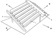
Fig. 1 is the perspective view of the heat pipe type composite parabolic heat collector placed of East and West direction that first embodiment that the utility model provides adopts;
Have among the figure: pipe type composite parabolic heat light-condensing and heat-collecting device 1, heat exchange box 2, fixed support 3;
Fig. 2 is the structural representation of the pipe type composite parabolic heat light-condensing and heat-collecting device 1 that adopts of first embodiment that the utility model provides;
Have among the figure: heat pipe 1-1, composite parabolic solar panel 1-2, glass tube 1-3;
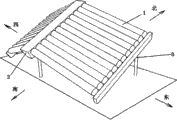
Fig. 3 is the perspective view of the heat pipe type composite parabolic heat collector placed of East and West direction that second embodiment that the utility model provides adopts;
Have among the figure: pipe type composite parabolic heat light-condensing and heat-collecting device 1, heat exchange box 2, fixed support 3;
Fig. 4 is the structural representation of the pipe type composite parabolic heat light-condensing and heat-collecting device 1 that adopts of second embodiment that the utility model provides;
Have among the figure: heat pipe 1-1, composite parabolic solar panel 1-2, glass tube 1-3.
The specific embodiment
Below in conjunction with accompanying drawing the utility model is described further.
The heat pipe type composite parabolic heat collector that East and West direction of the present utility model is placed, this heat pipe type composite parabolic heat collector comprises a plurality of pipe type composite parabolic heat light-condensing and heat-collecting devices 1, heat exchange box 2 and plurality of fixed support 3;
The heat-exchange end of pipe type composite parabolic heat light-condensing and heat-collecting device 1 is connected with heat exchange box 2, the thing both sides that are distributed in heat exchange box 2 of a plurality of pipe type composite parabolic heat light-condensing and heat-collecting device 1 symmetries; The direction on the long limit of heat exchange box 2 is that positive north deflection goes up certain angle; The direction on the long limit of the axial and heat exchange box 2 of pipe type composite parabolic heat light-condensing and heat-collecting device 1 is vertical, and the end that pipe type composite parabolic heat light-condensing and heat-collecting device 1 contacts with heat exchange box 2 exceeds certain distance than the other end of this device, to satisfy the normal operation of heat pipe; Plurality of fixed support 3 is connected with pipe type composite parabolic heat light-condensing and heat-collecting device 1 and heat exchange box 2, is used for supporting and fixedly pipe type composite parabolic heat light-condensing and heat-collecting device 1 and heat exchange box 2.
Pipe type composite parabolic heat light-condensing and heat-collecting device 1 comprises glass tube 1-3, is positioned at the heat pipe 1-1 and the composite parabolic solar panel 1-2 of glass tube 1-3 inside; Between heat pipe 1-1 and the glass tube 1-3 is vacuum; Composite parabolic solar panel 1-2 is installed in the outside of glass tube 1-3, the slit is arranged between composite parabolic solar panel 1-2 and the glass tube 1-3 and glass tube 1-3 semi-surrounding is lived.
Pipe type composite parabolic heat light-gathering heat collection pipe 1 comprises glass tube 1-3, is positioned at the heat pipe 1-1 and the composite parabolic solar panel 1-2 of glass tube 1-3 inside; Between heat pipe 1-1 and the glass tube 1-3 is vacuum; Composite parabolic solar panel 1-2 is installed in this vacuum and with glass tube 1-3 and contacts, and the slit is arranged between composite parabolic solar panel 1-2 and the heat pipe 1-1 and heat pipe 1-1 semi-surrounding is lived.
Fixed support 3 adopts the support that can regulate height, can change the long limit of heat exchange box 2 and the angle on ground by regulating this support.
The scope that the optically focused of composite parabolic solar panel 1-2 receives half-angle is 15 °-75 °.
The direction on the long limit of heat exchange box 2 is that positive north deflection goes up certain angle, the scope of this angle be local latitude ± 30 degree.
Embodiment 1
The heat pipe type composite parabolic heat collector that East and West direction is placed comprises 24 pipe type composite parabolic heat light-condensing and heat-collecting devices 1, heat exchange box 2, fixed support 3; The heat-exchange end of pipe type composite parabolic heat light-condensing and heat-collecting device 1 is connected with heat exchange box 2, the thing both sides that are distributed in heat exchange box 2 of 24 pipe type composite parabolic heat light-condensing and heat-collecting device 1 symmetries; The direction on the long limit of heat exchange box 2 is last 32 ° of a positive north deflection; The direction on the long limit of the axial and heat exchange box 2 of pipe type composite parabolic heat light-condensing and heat-collecting device 1 is vertical, and the end that pipe type composite parabolic heat light-condensing and heat-collecting device 1 contacts with heat exchange box 2 exceeds certain distance than the other end of this device, makes the axial and ground of this device be 20 ° angle; Fixed support 3 is connected with pipe type composite parabolic heat light-condensing and heat-collecting device 1 and heat exchange box 2, and is used for supporting and fixedly pipe type composite parabolic heat light-condensing and heat-collecting device 1 and heat exchange box 2.Heat exchange box 2 contains polyurethane insulation coating.Fixed support 3 adopts the support that can regulate height, can change the long limit of heat exchange box 2 and the angle on ground by regulating this support.
Pipe type composite parabolic heat light-condensing and heat-collecting device 1 comprises composite parabolic solar panel 1-2, glass tube 1-3, is positioned at the heat pipe 1-1 of glass tube 1-3 inside; Between heat pipe 1-1 and the glass tube 1-3 is vacuum, and composite parabolic solar panel 1-2 is installed in the outside of glass tube 1-3.Composite parabolic solar panel 1-2 adopts aluminium sheet, and glass tube 1-3 adopts high-boron-silicon glass 3.3.The length of heat pipe 1-1 is 1.5 meters.It is 30 ° that the optically focused of composite parabolic solar panel receives half-angle
The heat pipe type composite parabolic heat collector that the East and West direction that the utility model provides is placed comprises 24 pipe type composite parabolic heat light-gathering heat collection pipes 1, heat exchange box 2 and plurality of fixed support 3.The heat-exchange end of pipe type composite parabolic heat light-gathering heat collection pipe 1 is connected with heat exchange box 2, the thing both sides that are distributed in heat exchange box 2 of 24 pipe type composite parabolic heat light-gathering heat collection pipe 1 symmetries; The direction on the long limit of heat exchange box 2 is last 32 ° of a positive north deflection; The direction on the long limit of the axial and heat exchange box 2 of pipe type composite parabolic heat light-gathering heat collection pipe 1 is vertical, and the end that pipe type composite parabolic heat light-gathering heat collection pipe 1 contacts with heat exchange box 2 exceeds certain distance than the other end of this pipe, makes this pipe and ground be 20 ° angle; Plurality of fixed support 3 is connected with pipe type composite parabolic heat light-gathering heat collection pipe 1 and heat exchange box 2 respectively, and is used for supporting and fixedly pipe type composite parabolic heat light-gathering heat collection pipe 1 and heat exchange box 2.Heat exchange box 2 contains polyurethane insulation coating.Fixed support 3 adopts the support that can regulate height, can change the long limit of heat exchange box 2 and the angle on ground by regulating this support.
Pipe type composite parabolic heat light-gathering heat collection pipe 1 comprises composite parabolic solar panel 1-2, glass tube 1-3, is positioned at the heat pipe 1-1 of glass tube 1-3 inside; Between heat pipe 1-1 and the glass tube 1-3 is vacuum, and composite parabolic solar panel 1-2 is installed in this vacuum and with glass tube 1-3 and contacts, and between composite parabolic solar panel 1-2 and the heat pipe 1-1 slit is arranged.
Composite parabolic solar panel 1-2 adopts aluminium sheet, and glass tube 1-3 adopts high-boron-silicon glass.The length of heat pipe 1-1 is 1.5 meters.The reception half-angle of the optically focused of composite parabolic solar panel 1-2 is 45 °.
The utility model can also have other embodiment, and any trickle modification that all foundations technical spirit of the present invention is adopted, equivalent transformation, alternative formed technical scheme all drop within the claimed scope of the utility model.
Claims (7)
1. the heat pipe type composite parabolic heat collector placed of an East and West direction is characterized in that:
This heat pipe type composite parabolic heat collector comprises a plurality of pipe type composite parabolic heat light-condensing and heat-collecting devices (1), heat exchange box (2) and plurality of fixed support (3);
The heat-exchange end of pipe type composite parabolic heat light-condensing and heat-collecting device (1) is connected with heat exchange box (2), the thing both sides that are distributed in heat exchange box (2) of a plurality of pipe type composite parabolic heat light-condensing and heat-collecting devices (1) symmetry; The direction on the long limit of heat exchange box (2) is that positive north deflection goes up certain angle; The direction on the long limit of the axial and heat exchange box (2) of pipe type composite parabolic heat light-condensing and heat-collecting device (1) is vertical, and the end that pipe type composite parabolic heat light-condensing and heat-collecting device (1) contacts with heat exchange box (2) exceeds certain distance than the other end of this device, to satisfy the normal operation of heat pipe; Plurality of fixed support (3) is connected with pipe type composite parabolic heat light-condensing and heat-collecting device (1) and heat exchange box (2), is used for supporting and fixedly pipe type composite parabolic heat light-condensing and heat-collecting device (1) and heat exchange box (2).
2. the heat pipe type composite parabolic heat collector that East and West direction according to claim 1 is placed is characterized in that: pipe type composite parabolic heat light-condensing and heat-collecting device (1) comprises glass tube (1-3), is positioned at glass tube (1-3) inner heat pipe (1-1) and composite parabolic solar panel (1-2); Between heat pipe (1-1) and the glass tube (1-3) is vacuum; Composite parabolic solar panel (1-2) is installed in the outside of glass tube (1-3), the slit is arranged between composite parabolic solar panel (1-2) and the glass tube (1-3) and glass tube (1-3) semi-surrounding is lived.
3. the heat pipe type composite parabolic heat collector that East and West direction according to claim 1 is placed is characterized in that: pipe type composite parabolic heat light-gathering heat collection pipe (1) comprises glass tube (1-3), is positioned at glass tube (1-3) inner heat pipe (1-1) and composite parabolic solar panel (1-2); Between heat pipe (1-1) and the glass tube (1-3) is vacuum; Composite parabolic solar panel (1-2) is installed in this vacuum and with glass tube (1-3) and contacts, and the slit is arranged between composite parabolic solar panel (1-2) and the heat pipe (1-1) and heat pipe (1-1) semi-surrounding is lived.
4. the heat pipe type composite parabolic heat collector that East and West direction according to claim 1 is placed is characterized in that: fixed support (3) adopts the support that can regulate height, can change the long limit of heat exchange box (2) and the angle on ground by regulating this support.
5. according to the heat pipe type composite parabolic heat collector of claim 2 or 3 described East and West directions placements, it is characterized in that: heat exchange box (2) contains polyurethane insulation coating, and composite parabolic solar panel (1-2) adopts aluminium sheet, and glass tube (1-3) adopts high-boron-silicon glass.
6. according to the heat pipe type composite parabolic heat collector of claim 2 or 3 described East and West directions placements, it is characterized in that: the scope that the optically focused of composite parabolic solar panel (1-2) receives half-angle is 15 °-75 °.
7. the heat pipe type composite parabolic heat collector that East and West direction according to claim 1 is placed is characterized in that: the direction on the long limit of heat exchange box (2) goes up certain angle for positive north deflection, the scope of this angle be local latitude ± 30 spend.
Priority Applications (1)
| Application Number | Priority Date | Filing Date | Title |
|---|---|---|---|
| CN201020166980XU CN201666674U (en) | 2010-04-21 | 2010-04-21 | Transmeridionally placed heat pipe type compound parabolic heat collector |
Applications Claiming Priority (1)
| Application Number | Priority Date | Filing Date | Title |
|---|---|---|---|
| CN201020166980XU CN201666674U (en) | 2010-04-21 | 2010-04-21 | Transmeridionally placed heat pipe type compound parabolic heat collector |
Publications (1)
| Publication Number | Publication Date |
|---|---|
| CN201666674U true CN201666674U (en) | 2010-12-08 |
Family
ID=43267633
Family Applications (1)
| Application Number | Title | Priority Date | Filing Date |
|---|---|---|---|
| CN201020166980XU Expired - Fee Related CN201666674U (en) | 2010-04-21 | 2010-04-21 | Transmeridionally placed heat pipe type compound parabolic heat collector |
Country Status (1)
| Country | Link |
|---|---|
| CN (1) | CN201666674U (en) |
Cited By (2)
| Publication number | Priority date | Publication date | Assignee | Title |
|---|---|---|---|---|
| CN101818945A (en) * | 2010-04-21 | 2010-09-01 | 东南大学 | Heat pipe type composite parabolic heat collector arranged in east-west direction |
| CN102168890A (en) * | 2011-03-28 | 2011-08-31 | 杭州立扬聚光蓄热科技有限公司 | Loop design for slot type solar heat power plant |
-
2010
- 2010-04-21 CN CN201020166980XU patent/CN201666674U/en not_active Expired - Fee Related
Cited By (2)
| Publication number | Priority date | Publication date | Assignee | Title |
|---|---|---|---|---|
| CN101818945A (en) * | 2010-04-21 | 2010-09-01 | 东南大学 | Heat pipe type composite parabolic heat collector arranged in east-west direction |
| CN102168890A (en) * | 2011-03-28 | 2011-08-31 | 杭州立扬聚光蓄热科技有限公司 | Loop design for slot type solar heat power plant |
Similar Documents
| Publication | Publication Date | Title |
|---|---|---|
| CN201259343Y (en) | Multi-surface compound wire focusing groove type solar medium and high temperature heat collection and heat storage system | |
| CN102589159B (en) | Photovoltaic and photo-thermal composite parabolic condenser with vacuum tube | |
| CN102954601A (en) | Pantile solar concentration heat collector | |
| CN101699191A (en) | Integrally packaged type solar heat collector with combined curved surface for light collection and vacuum tube for heat collection | |
| KR101997761B1 (en) | Combined solar thermal and photovoltaics system using hybird solar cell based on concentrated type and planar type | |
| CN102013843A (en) | Controllable double-state light reflecting and concentrating solar heat collecting generator | |
| CN201352013Y (en) | Novel solar light and heat collecting system | |
| CN201926020U (en) | Photoelectric driven solar air heater | |
| CN201666674U (en) | Transmeridionally placed heat pipe type compound parabolic heat collector | |
| CN103673320A (en) | Solar heat collection device | |
| CN203286779U (en) | Road space three-dimensional linear Fresnel type solar condensation device | |
| CN101169286A (en) | Reflection type straightforward focusing high temperature solar energy heat collector | |
| CN101929744A (en) | Tower type solar concentrating system | |
| WO2014026575A1 (en) | Device for integrating solar energy and building | |
| CN101876516A (en) | Distributed new energy supply method for town | |
| CN207320145U (en) | A kind of concentrating photovoltaic photo-thermal component and array for being disposed with double side photovoltaic battery piece | |
| CN101818945A (en) | Heat pipe type composite parabolic heat collector arranged in east-west direction | |
| CN101867320A (en) | Photoelectric photo-thermal combined vacuum straight-through heat collector for trench light condensing system | |
| CN101976973A (en) | Controllable double-state light-reflecting and light-condensing solar heat-collecting generating device | |
| CN201740267U (en) | Wire tower-type solar energy light-gathering heat collecting system | |
| CN102683461B (en) | A kind of Photospot solar device | |
| CN201637144U (en) | Wall-mounted heat collector adopting semi-edge compound parabolic light condensing devices | |
| CN101876480A (en) | Distributed new energy supply system for town | |
| CN201583011U (en) | Movable compound parabolic condenser | |
| CN201063556Y (en) | Solar energy concentration photovoltaic and photothermal cogeneration device |
Legal Events
| Date | Code | Title | Description |
|---|---|---|---|
| C14 | Grant of patent or utility model | ||
| GR01 | Patent grant | ||
| C17 | Cessation of patent right | ||
| CF01 | Termination of patent right due to non-payment of annual fee |
Granted publication date: 20101208 Termination date: 20130421 |