CN201662427U - Portable weighing support for livestock - Google Patents
Portable weighing support for livestock Download PDFInfo
- Publication number
- CN201662427U CN201662427U CN201020156938XU CN201020156938U CN201662427U CN 201662427 U CN201662427 U CN 201662427U CN 201020156938X U CN201020156938X U CN 201020156938XU CN 201020156938 U CN201020156938 U CN 201020156938U CN 201662427 U CN201662427 U CN 201662427U
- Authority
- CN
- China
- Prior art keywords
- sleeve pipe
- weighing
- pipe
- horizontal
- screw
- Prior art date
- Legal status (The legal status is an assumption and is not a legal conclusion. Google has not performed a legal analysis and makes no representation as to the accuracy of the status listed.)
- Expired - Fee Related
Links
Images

Landscapes
- Catching Or Destruction (AREA)
Abstract
The utility model relates to a weighing device for livestock husbandry, in particular to a portable weighing support for livestock, which is applicable to on-site use, and comprises a weighing cloth bag, a weighing support and a fastener which are matched with one another, wherein the weighing support consists of a vertical casing, a vertical core tube, an upper horizontal casing, an upper horizontal core tube, a lower horizontal casing and a lower horizontal core tube which are symmetrical, as well as T-shaped frames which are symmetrical; the body of the weighting support is provided with a winding roller which rotates by a hand-operated handle; the winding roller is connected with a steel wire by a winding manner; the other end of the steel wire is coupled at the upper end of the weighing support bypass a guide pulley; the other end of the steel wire is served as a connecting shackle of the suspension end; the weighting cloth bag is formed by matching connection of a cloth piece and coupling ropes; and the symmetric coupling ropes are respectively and fixedly connected at two sides of the cloth piece. The portable weighing support for livestock has advantages of simple and reasonable structure, convenient and fast use, flexible weighing, smartness and convenient carrying without hurt to the livestock, and facilitates the wide application in practical production of a pasturing area.
Description
Technical field
The utility model relates to the weighing device that a kind of animal husbandry is used, and is applicable to on-the-spot use, the particularly portable frame of weighing for animals.
Background technology
Weighing of hog continued to use traditional mode always in animal husbandry is produced, mainly be after pinioning the four limbs of livestock it to be lifted, carry out weighing, this main mode with the manually-operated load-bearing not only expends great amount of manpower, and the speed of weighing is also very slow, waste time and energy, when the four limbs of binding pin livestock, the four limbs of livestock are easy to by ankle injury, if anaphase is untimely, the four limbs of livestock cause infection easily, cause once and cause selling to be worth and reducing of sheep etc. after unexpected, promptly cause the livestock selling price to reduce, influence economic benefit.
The utility model content
The purpose of this utility model is to provide a kind of portable frame of weighing for animals, and it is simple and reasonable for structure, and is convenient to use, weigh flexibly, small and exquisite, easy to carry, can not injure livestock, is convenient to be used widely in the actual production in pastoral area.
The purpose of this utility model is achieved in that a kind of portable frame of weighing for animals, by the pocket of weighing, frame and the securing member composition that matches of weighing, the perpendicular sleeve pipe of frame of weighing by symmetry, perpendicular core pipe, go up horizontal sleeve pipe, go up horizontal core pipe, following horizontal sleeve pipe, the T shape of horizontal core pipe and symmetry is configured to down, the perpendicular sleeve pipe bottom of symmetry respectively affixed horizontal sleeve pipe and horizontal core pipe down down, horizontal core pipe is set in down in the horizontal sleeve pipe movingly down, perpendicular core pipe is installed respectively in the perpendicular sleeve pipe of symmetry movingly, perpendicular core pipe upper end affixed respectively go up horizontal sleeve pipe and last horizontal core pipe, going up horizontal core pipe is set in the horizontal sleeve pipe movingly, the inboard, middle part of the perpendicular sleeve pipe of symmetry is being provided with respectively being much of, following pipe box and T shape frame, T shape frame is made of with vertical affixed galianconism with it long-armed, long-armed its upper end engage sleeves of T shape frame is connected in the pipe box, and long-armed its lower end engage sleeves of T shape frame is connected to down in the pipe box; Weigh the winding roller that rotates by crank handle is installed on the frame support body, the steel wire that has been intertwined and connected on the winding roller, the steel wire other end are walked around leading block and are articulated in the frame upper end of weighing, and the steel wire other end is as dangling the end connecting shackle; Weigh pocket by the cloth sheet with articulate rope and be connected and constitute, symmetry articulate the both sides that rope is fixed in the cloth sheet respectively; Perpendicular core pipe is installed in the perpendicular sleeve pipe and fixes movingly and by the length that fixture stretches out in the perpendicular sleeve pipe perpendicular core pipe with it, last horizontal core pipe is installed in the horizontal sleeve pipe to be fixed with it movingly and by the length that fixture makes horizontal core pipe stretch out horizontal sleeve pipe, and following horizontal core pipe is installed in down in the horizontal sleeve pipe and fixes movingly and by the length that fixture makes down horizontal core pipe stretch out following horizontal sleeve pipe with it.
The utility model is applicable to calf, lamb, weighing measurement and the body measurement of the livestocks such as sheep that grow up, makes the breeding work personnel livestocks such as calf, lamb of can conveniently weighing.The utility model is made of sleeve pipe and core pipe on the whole, can adjust the height and the width of the frame of weighing according to different needs of work flexibly, during use, it is vertically stretched fixing that vertical stretching will be erected the core pipe, cross directional stretch is pulled out upper and lower horizontal sleeve pipe respectively simultaneously with upper and lower horizontal core pipe and is fixed, T shape frame is taken out (making the upper and lower pipe box of long-armed disengaging of T shape frame) from the frame of weighing, stretch out the length that sleeve pipe stretches out by fixture fixed core pipe, and then the galianconism of T shape frame stretched into perpendicular sleeve bottom is fixing to get final product.When weighing, earlier with livestock four limbs pockets such as lamb or calves in the pocket of weighing, the pocket of will weighing again hangs on the hook by suspension strop, is connected the weighing apparatus that articulates on the rope and observes, writes down its body weight by being serially connected in.If during insufficient height, can rotate the length that winding roller is regulated steel wire, to regulate the height that lamb or calf etc. hang by crank handle.The utility model is simple and reasonable for structure, and is convenient to use, weigh flexibly, small and exquisite, easy to carry, can not injure livestock, is convenient to be used widely in the actual production in pastoral area.
Description of drawings
The utility model is described in further detail below in conjunction with accompanying drawing.
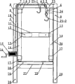
Fig. 1 is in the structural representation of contraction state for the utility model embodiment 1;
Fig. 2 is the weigh structural representation of pocket of the utility model;
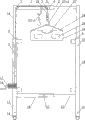
Fig. 3 is in the structural representation of extended state for the utility model;
Fig. 4 is the side-looking structural representation of Fig. 3;
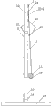
Fig. 5 is the side-looking structural representation of the utility model embodiment 2.
Embodiment
A kind of portable frame of weighing for animals, extremely shown in Figure 5 as Fig. 1, by the pocket of weighing, frame and the securing member composition that matches of weighing, the perpendicular sleeve pipe 8 of frame of weighing by symmetry, perpendicular core pipe 10, go up horizontal sleeve pipe 4, go up horizontal core pipe 2, following horizontal sleeve pipe 18, the T shape of down horizontal core pipe 21 and symmetry is configured to, perpendicular sleeve pipe 8 bottoms of symmetry respectively affixed down horizontal sleeve pipe 18 and horizontal core pipe 21 down, horizontal core pipe 21 is set in down in the horizontal sleeve pipe 18 movingly down, perpendicular core pipe 10 is installed respectively in the perpendicular sleeve pipe 8 of symmetry movingly, perpendicular core pipe 10 upper ends affixed respectively go up horizontal sleeve pipe 4 and last horizontal core pipe 2, going up horizontal core pipe 2 is set in the horizontal sleeve pipe 4 movingly, the inboard, middle part of the perpendicular sleeve pipe 8 of symmetry is being provided with respectively being much of, following pipe box 6,17 and T shape frame, T shape frame constitutes with vertical affixed galianconism 13 with it by long-armed 14, long-armed 14 its upper end engage sleeves of T shape frame are connected in the pipe box 6, and long-armed 14 its lower end engage sleeves of T shape frame are connected to down in the pipe box 17; Weigh the winding roller 15 that rotates by crank handle 16 is installed on the frame support body, the steel wire 5 that has been intertwined and connected on the winding roller 15, the steel wire other end are walked around leading block and are articulated in the frame upper end of weighing, and the steel wire other end is as the end connecting shackle 25-2 that dangles; Weigh pocket by cloth sheet 29 with articulate rope 28 and be connected and constitute, symmetry articulate the both sides that rope 28 is fixed in cloth sheet 29 respectively; Perpendicular core pipe 10 is installed in the perpendicular sleeve pipe 8 and fixes movingly and by the length that fixture stretches out in the perpendicular sleeve pipe 8 perpendicular core pipe 10 with it, last horizontal core pipe 2 is installed in the horizontal sleeve pipe 4 to be fixed with it movingly and by the length that fixture makes horizontal core pipe 2 stretch out horizontal sleeve pipe 4, and following horizontal core pipe 21 is installed in down in the horizontal sleeve pipe 18 and fixes movingly and by the length that fixture makes down horizontal core pipe 21 stretch out following horizontal sleeve pipe 18 with it.
Also match with perpendicular sleeve pipe 8 lower port in galianconism 13 its terminations of T shape frame, in use, T shape frame is taken out (making the upper and lower pipe box of long-armed disengaging of T shape frame) from the frame of weighing, the galianconism 13 of T shape frame can cooperate to stretch into perpendicular sleeve pipe 8 bottom tube chambers and cooperates with long-armed 14 of T shape frame makes the frame setting of weighing, the pocket of will weighing again hangs over hook by suspension strop and goes up (articulate rope 28 cooperate to be articulated in make 29 suspentions of cloth sheet on the suspension hook 25-2), is connected the weighing apparatus that articulates on the rope and observes, writes down its body weight by being serially connected in.
Stretch in horizontal cross and to weigh in the process of frame, can make overlap joint sleeve pipe 11 break away from the galianconism 13 of T shape framves, T shape frame can be broken away from the frame support body of weighing then, the galianconism 13 of T shape frame is inserted in the perpendicular sleeve pipe 8 bottom mouths of pipe.
Described fixture is made of bolt and nut, and bolt is made of upper lateral fastening bolt 31, the horizontal fastening bolt 33 of vertical fastening bolt 32 in top and middle part; Vertical fastening bolt 32 its screw rods in top pass the screw 26 of setting on the perpendicular core pipe 10 and the screw 9 that perpendicular sleeve pipe 8 tops are provided with by screw thread, on this screw rod body of rod that stretches out perpendicular sleeve pipe 8 tube walls through screw 9 nut is installed, nut and this screw rod length that makes perpendicular core pipe 10 stretch out the perpendicular sleeve pipe 8 upper end mouths of pipe that matches is fixed; Upper lateral fastening bolt 31 its screw rods pass on the horizontal core pipe 2 screw 23 that is provided with on the screw 1 that is provided with and the last horizontal sleeve pipe 4 by screw thread, on this screw rod body of rod that stretches out horizontal sleeve pipe 4 tube walls through screw 23 nut is installed, nut and this screw rod length that makes horizontal core pipe 2 stretch out the horizontal sleeve pipe 4 upper end mouths of pipe that matches is fixed; Vertical fastening bolt 33 its screw rods in bottom pass down the screw 19 that is provided with on the horizontal core pipe 21 and descend the screw 22 that is provided with on the horizontal sleeve pipe 18 by screw thread, on this screw rod body of rod that stretches out following horizontal sleeve pipe 18 tube walls through screw 22 nut is installed, nut and this screw rod match and make down horizontal core pipe 21 stretch out the length of horizontal sleeve pipe 18 mouths of pipe to fix.
Galianconism 13 cooperations of T shape frame are stretched into perpendicular sleeve pipe 8 bottom tube chambers and by fixture T shape frame and perpendicular sleeve pipe 8 are fixed.Described fixture constitutes (above-mentioned securing member is installed principle as herein) by vertical fastening bolt 34 in bottom and nut 35, vertical fastening bolt 34 its screw rods in bottom pass the screw 12 of setting on the T shape frame galianconism 13 and the screw 20 that perpendicular sleeve pipe 8 bottoms are provided with by screw thread, on this screw rod body of rod that stretches out perpendicular sleeve pipe 8 tube walls through screw 20 nut 35 is installed, nut 35 and this screw rod fix T shape frame and perpendicular sleeve pipe 8.
The installation that matches with ratchet device of described winding roller 15, these ratchet device control winding roller 15 unidirectional rotations are wrapped on the winding roller 15 steel wire 5; The steel wire other end is walked around leading block by weighing apparatus 24 and is articulated in the frame upper end of weighing, described weighing apparatus 24 is positioned at the frame support body upper end of weighing, the end that dangles of steel wire 5 is by weighing apparatus 24 connecting shackle 25-2, suspension hook 25-2 articulates the load-bearing pocket by suspension strop 28, perhaps also affixed hook 25-1 on horizontal sleeve pipe articulates rope 28 and cooperates to be articulated in by weighing apparatus 24 cloth sheet 29 is articulated on the hook 25-1; Weighing apparatus 24 is electronic scale treasure or spring balance treasure.
As shown in Figure 2, described cloth sheet 29 is rectangle and is made of canvas, the rope 27 that is connecting symmetry in cloth sheet 29 both sides respectively, homonymy is being provided with rope 27 and suspension strop 28 on each side of the relative both sides of cloth sheet 29, rope 27 length are trapped among wherein less than the suspension strop 28 and the rope 28 that is draped, can when holding up fast built on stilts such as lamb or calf with the load-bearing pocket, lift, wrap up lamb or calf etc. with rope 27.
Offering four through holes 30 on the described cloth sheet, the livestock four limbs are being passed wherein, making its four limbs be in vacant state, keeping the trunk lower surface of livestock directly to contact cloth diaper sheet 29 inside surfaces of weighing, conveniently weighing.
As shown in Figure 5, roller 35 is installed, after frame is weighed in contraction, can carries out by this roller 35 in perpendicular sleeve pipe 8 lower ends.Leading block is made of to pulley 3 and secondary leading block 7 leading, dominates and is installed in horizontal sleeve pipe 4 mouth of pipe places to pulley 3, and secondary leading block 7 is installed in perpendicular core pipe 1 upper end or is installed in the junction of horizontal sleeve pipe 4 and perpendicular core pipe 1.
The galianconism 13 of T shape frame stretches into overlap joint sleeve pipe 11 respectively movingly is sleeved on the galianconism 13 overlap joint sleeve pipe 11.
Claims (10)
1. portable frame of weighing for animals, it is characterized in that: by the pocket of weighing, frame and the securing member composition that matches of weighing, the perpendicular sleeve pipe (8) of frame of weighing by symmetry, perpendicular core pipe (10), go up horizontal sleeve pipe (4), go up horizontal core pipe (2), following horizontal sleeve pipe (18), the T shape of horizontal core pipe (21) and symmetry is configured to down, perpendicular sleeve pipe (8) bottom of symmetry respectively affixed horizontal sleeve pipe (18) and time horizontal core pipe (21) down, horizontal core pipe (21) is set in down in the horizontal sleeve pipe (18) movingly down, perpendicular core pipe (10) is installed respectively in the perpendicular sleeve pipe (8) of symmetry movingly, perpendicular core pipe (10) upper end affixed respectively go up horizontal sleeve pipe (4) and last horizontal core pipe (2), going up horizontal core pipe (2) is set in the horizontal sleeve pipe (4) movingly, the inboard, middle part of the perpendicular sleeve pipe (8) of symmetry is being provided with respectively being much of, following pipe box (6), (17) and T shape frame, T shape frame is made of with vertical affixed galianconism (13) with it long-armed (14), long-armed (14) of T shape frame its upper end engage sleeves is connected in the pipe box (6), and long-armed (14) its lower end engage sleeves of T shape frame is connected to down in the pipe box (17); Weigh the winding roller (15) that rotates by crank handle (16) is installed on the frame support body, steel wire (5) has been intertwined and connected on the winding roller (15), the steel wire other end is walked around leading block and is articulated in the frame upper end of weighing, and the steel wire other end is as the end connecting shackle (25-2) that dangles; Weigh pocket by cloth sheet (29) with articulate rope (28) formation that is connected, symmetry articulate the both sides that rope (28) is fixed in cloth sheet (29) respectively; Perpendicular core pipe (10) is installed in the perpendicular sleeve pipe (8) and fixes movingly and by the length that fixture stretches out in the perpendicular sleeve pipe (8) perpendicular core pipe (10) with it, last horizontal core pipe (2) is installed in the horizontal sleeve pipe (4) to be fixed with it movingly and by the length that fixture makes horizontal core pipe (2) stretch out horizontal sleeve pipe (4), and following horizontal core pipe (21) is installed in down in the horizontal sleeve pipe (18) and fixes movingly and by the length that fixture makes down horizontal core pipe (21) stretch out following horizontal sleeve pipe (18) with it.
2. the portable frame of weighing for animals according to claim 1, it is characterized in that: described fixture is made of bolt and nut, and bolt is made of upper lateral fastening bolt (31), the horizontal fastening bolt of vertical fastening bolt in top (32) and middle part (33); Its screw rod of the vertical fastening bolt in top (32) passes perpendicular core pipe (10) by screw thread and goes up the screw (26) of setting and the screw (9) that perpendicular sleeve pipe (8) top is provided with, on this screw rod body of rod that stretches out perpendicular sleeve pipe (8) tube wall through screw (9) nut is installed, nut and this screw rod length that makes perpendicular core pipe (10) stretch out perpendicular sleeve pipe (8) the upper end mouth of pipe that matches is fixed; Its screw rod of upper lateral fastening bolt (31) passes horizontal core pipe (2) by screw thread and goes up the screw (1) of setting and the screw (23) that last horizontal sleeve pipe (4) upward is provided with, on this screw rod body of rod that stretches out horizontal sleeve pipe (4) tube wall through screw (23) nut is installed, nut and this screw rod match and make horizontal core pipe (2) stretch out on the horizontal sleeve pipe (4) length of the mouth of pipe to fix; Its screw rod of the vertical fastening bolt in bottom (33) passes down horizontal core pipe (21) by screw thread and goes up the screw (19) of setting and the screw (22) that following horizontal sleeve pipe (18) upward is provided with, on this screw rod body of rod that stretches out following horizontal sleeve pipe (18) tube wall through screw (22) nut is installed, nut and this screw rod match and make down horizontal core pipe (21) stretch out the length of horizontal sleeve pipe (18) mouth of pipe to fix.
3. the portable frame of weighing for animals according to claim 1 is characterized in that: galianconism (13) cooperation of T shape frame is stretched into perpendicular sleeve pipe (8) bottom tube chamber and by fixture T shape frame and perpendicular sleeve pipe (8) is fixed.
4. the portable frame of weighing for animals according to claim 3, it is characterized in that: described fixture is made of vertical fastening bolt in bottom (34) and nut (35), its screw rod of the vertical fastening bolt in bottom (34) passes T shape frame galianconism (13) by screw thread and goes up the screw (12) of setting and the screw (20) that perpendicular sleeve pipe (8) bottom is provided with, on this screw rod body of rod that stretches out perpendicular sleeve pipe (8) tube wall through screw (20) nut (35) is installed, nut (35) and this screw rod fix T shape frame and perpendicular sleeve pipe (8).
5. the portable frame of weighing for animals according to claim 1 is characterized in that: described winding roller (15) installation that matches with ratchet device, and the unidirectional rotation of this ratchet device control winding roller (15) is wrapped on the winding roller (15) steel wire (5); The steel wire other end is walked around leading block by weighing apparatus (24) and is articulated in the frame upper end of weighing, described weighing apparatus (24) is positioned at the frame support body upper end of weighing, the end that dangles of steel wire (5) is by weighing apparatus (24) connecting shackle (25-2), suspension hook (25-2) articulates the load-bearing pocket by suspension strop (28), perhaps also affixed hook (25-1) on horizontal sleeve pipe articulates rope (28) and cooperates to be articulated in by weighing apparatus (24) cloth sheet (29) is articulated on the hook (25-1); Weighing apparatus (24) is electronic scale treasure or spring balance treasure.
6. the portable frame of weighing for animals according to claim 1, it is characterized in that: described cloth sheet (29) is rectangle and is made of canvas, the rope (27) that is connecting symmetry in cloth sheet (29) both sides respectively, homonymy is being provided with rope (27) and suspension strop (28) on each side of the relative both sides of cloth sheet (29), and rope (27) length is trapped among wherein less than the suspension strop (28) and the rope (28) that is draped.
7. the portable frame of weighing for animals according to claim 1 is characterized in that: offering four through holes (30) on the described cloth sheet.
8. the portable frame of weighing for animals according to claim 1 is characterized in that: in perpendicular sleeve pipe (8) lower end roller (35) is installed.
9. the portable frame of weighing for animals according to claim 1, it is characterized in that: leading block is made of to pulley (3) and secondary leading block (7) leading, dominate and be installed in horizontal sleeve pipe (4) mouth of pipe place to pulley (3), secondary leading block (7) is installed in perpendicular core pipe (1) upper end or is installed in horizontal sleeve pipe (4) and the junction of perpendicular core pipe (1).
10. the portable frame of weighing for animals according to claim 1 is characterized in that: the galianconism (13) of T shape frame stretches into overlap joint sleeve pipe (11) respectively movingly is sleeved on the galianconism (13) overlap joint sleeve pipe (11).
Priority Applications (1)
| Application Number | Priority Date | Filing Date | Title |
|---|---|---|---|
| CN201020156938XU CN201662427U (en) | 2010-04-13 | 2010-04-13 | Portable weighing support for livestock |
Applications Claiming Priority (1)
| Application Number | Priority Date | Filing Date | Title |
|---|---|---|---|
| CN201020156938XU CN201662427U (en) | 2010-04-13 | 2010-04-13 | Portable weighing support for livestock |
Publications (1)
| Publication Number | Publication Date |
|---|---|
| CN201662427U true CN201662427U (en) | 2010-12-01 |
Family
ID=43232846
Family Applications (1)
| Application Number | Title | Priority Date | Filing Date |
|---|---|---|---|
| CN201020156938XU Expired - Fee Related CN201662427U (en) | 2010-04-13 | 2010-04-13 | Portable weighing support for livestock |
Country Status (1)
| Country | Link |
|---|---|
| CN (1) | CN201662427U (en) |
Cited By (8)
| Publication number | Priority date | Publication date | Assignee | Title |
|---|---|---|---|---|
| CN103416319A (en) * | 2012-12-06 | 2013-12-04 | 华中农业大学 | Holding electronic cage scale for live pigs |
| CN108344480A (en) * | 2018-01-25 | 2018-07-31 | 北京农业信息技术研究中心 | A kind of poultry automatic weighing method and system |
| CN109387270A (en) * | 2018-11-26 | 2019-02-26 | 大连派欧机电设备有限公司 | A kind of Internet of Things meausring apparatus and method |
| CN109612560A (en) * | 2018-11-29 | 2019-04-12 | 江苏好三由信息科技有限公司 | A kind of tonnage of ship gauge |
| CN109804942A (en) * | 2019-04-02 | 2019-05-28 | 浙江省农业科学院 | A kind of livestock-raising weighing device |
| CN110006512A (en) * | 2019-05-07 | 2019-07-12 | 贵州师范大学 | A kind of Karst region cattle and sheep weighing device and its weighing method |
| CN112040778A (en) * | 2018-05-01 | 2020-12-04 | 马瑞奥家禽肉私人有限公司 | System for processing slaughter products and method for adjusting the mutual positioning of product carriers of such a system |
| CN112110358A (en) * | 2020-08-12 | 2020-12-22 | 刘�东 | Multifunctional weighing device for animal husbandry |
-
2010
- 2010-04-13 CN CN201020156938XU patent/CN201662427U/en not_active Expired - Fee Related
Cited By (11)
| Publication number | Priority date | Publication date | Assignee | Title |
|---|---|---|---|---|
| CN103416319A (en) * | 2012-12-06 | 2013-12-04 | 华中农业大学 | Holding electronic cage scale for live pigs |
| CN103416319B (en) * | 2012-12-06 | 2014-09-03 | 华中农业大学 | Holding electronic cage scale for live pigs |
| CN108344480A (en) * | 2018-01-25 | 2018-07-31 | 北京农业信息技术研究中心 | A kind of poultry automatic weighing method and system |
| CN108344480B (en) * | 2018-01-25 | 2023-12-22 | 北京农业信息技术研究中心 | Automatic weighing method and system for poultry |
| CN112040778A (en) * | 2018-05-01 | 2020-12-04 | 马瑞奥家禽肉私人有限公司 | System for processing slaughter products and method for adjusting the mutual positioning of product carriers of such a system |
| CN112040778B (en) * | 2018-05-01 | 2022-02-25 | 马瑞奥家禽肉私人有限公司 | System for processing slaughter products and method for adjusting the mutual positioning of product carriers of such a system |
| CN109387270A (en) * | 2018-11-26 | 2019-02-26 | 大连派欧机电设备有限公司 | A kind of Internet of Things meausring apparatus and method |
| CN109612560A (en) * | 2018-11-29 | 2019-04-12 | 江苏好三由信息科技有限公司 | A kind of tonnage of ship gauge |
| CN109804942A (en) * | 2019-04-02 | 2019-05-28 | 浙江省农业科学院 | A kind of livestock-raising weighing device |
| CN110006512A (en) * | 2019-05-07 | 2019-07-12 | 贵州师范大学 | A kind of Karst region cattle and sheep weighing device and its weighing method |
| CN112110358A (en) * | 2020-08-12 | 2020-12-22 | 刘�东 | Multifunctional weighing device for animal husbandry |
Similar Documents
| Publication | Publication Date | Title |
|---|---|---|
| CN201662427U (en) | Portable weighing support for livestock | |
| CN207163606U (en) | A kind of Physical Experiment weight beam | |
| CN202270087U (en) | Livestock binding frame | |
| CN206196723U (en) | A kind of full-automatic fishing net | |
| CN106720219B (en) | Automatic kelp airing system | |
| CN201817047U (en) | Suspension transportation device for greenhouse | |
| CN206725057U (en) | A kind of aquatic products weighing system | |
| CN202620603U (en) | Multifunctional combined household body-building device | |
| CN205124384U (en) | Laborsaving apple device of plucking | |
| CN208741192U (en) | Sheep operation Shelf for keeing | |
| CN201358764Y (en) | Balance weight structure of vertical oil extractor | |
| CN205242117U (en) | Suspension type clothing water -collection device that dries in air | |
| CN210784820U (en) | Baoding device for breeding | |
| CN207877090U (en) | A kind of container suspender | |
| CN201705011U (en) | Multifunctional fence | |
| CN207118552U (en) | Can rain-proof fish flake | |
| CN205631432U (en) | Setting device of bicycle tube | |
| CN205035665U (en) | Clothes hanger is shone to hand formula | |
| CN206294726U (en) | Plastic-steel belt composite membrane cultivates frame | |
| CN109042439A (en) | A kind of mariculture feed system with weighing system feeder | |
| CN109042440A (en) | A kind of mariculture feed system with seawater slug feeder | |
| CN220951005U (en) | A hand plate hoist for manual jack-up | |
| CN205061132U (en) | Stone device on carding machine | |
| CN208934525U (en) | A kind of portable outdoor safety fence | |
| CN109042438A (en) | A kind of mariculture feed system with feeder and crane |
Legal Events
| Date | Code | Title | Description |
|---|---|---|---|
| C14 | Grant of patent or utility model | ||
| GR01 | Patent grant | ||
| C17 | Cessation of patent right | ||
| CF01 | Termination of patent right due to non-payment of annual fee |
Granted publication date: 20101201 Termination date: 20130413 |