CN201658728U - Anesthetic reciprocating loop inhaling device - Google Patents
Anesthetic reciprocating loop inhaling device Download PDFInfo
- Publication number
- CN201658728U CN201658728U CN2010201642493U CN201020164249U CN201658728U CN 201658728 U CN201658728 U CN 201658728U CN 2010201642493 U CN2010201642493 U CN 2010201642493U CN 201020164249 U CN201020164249 U CN 201020164249U CN 201658728 U CN201658728 U CN 201658728U
- Authority
- CN
- China
- Prior art keywords
- anesthetic
- air bag
- breathing mask
- anesthesia
- anesthetis
- Prior art date
- Legal status (The legal status is an assumption and is not a legal conclusion. Google has not performed a legal analysis and makes no representation as to the accuracy of the status listed.)
- Expired - Fee Related
Links
Images
Abstract
The utility model provides an anesthetic reciprocating loop inhaling device, which belongs to the technical field of medical appliances, and structurally comprises an anesthetic air bag, a threaded pipe and a breathing mask, wherein a CO2 absorber is connected between the anesthetic air bag and the breathing mask, an elbow is connected at the other end of the threaded pipe, the breathing mask is connected at the tail end of the threaded pipe, an expiratory valve and an oxygen connecting pipe are arranged on the elbow respectively, an alternate air source connecting pipe is arranged on the elbow, and an anesthetic injecting connector is arranged at the tail part of the anesthetic air bag. The CO2 absorber additionally arranged between the anesthetic air bag and the threaded pipe of the anesthetic reciprocating loop inhaling device is adopted to absorb the expiratory air, so as to re-inhale the anesthetic air, furthermore, other extra air sources can be added according to the condition of an anesthesia patient to enable the anesthesia to be operated smoothly.
Description
Technical field
This utility model relates to technical field of medical instruments, the reciprocal loop of specifically a kind of anesthetis suction apparatus.
Background technology
General, the anesthesia incoming call device under the prior art is the operating room apparatus mostly, and it is bulky, the use complex operation, and corrective maintenance expense height is masterly at the anesthesia procedure of operating room.Yet in the open air or when going out first aid, can't use large-scale anesthesia equipment, can only revert to easy anesthesia outfit, great majority can adopt injecting anesthetic, but the injecting anesthetic risk is higher, sometimes be difficult to calculate rapidly and determine dosage and control, this moment, suction anesthesia then can be played beneficial effect to a certain extent.But the inhalation anaesthesia apparatus of some closed circuit uses and can not produce operation fast and easily because the equipment of circulating system is loaded down with trivial details, causes to a certain extent negative effect for first aid and open-air operation.
Summary of the invention
Technical assignment of the present utility model is to solve the deficiencies in the prior art, and the reciprocal loop of a kind of anesthetis suction apparatus is provided.
The technical solution of the utility model realizes in the following manner, the reciprocal loop of this anesthetis suction apparatus, and its structure comprises anesthesia air bag, corrugated tubing and breathing mask, is connected with CO between anesthesia air bag and the corrugated tubing
2Absorber, the other end of corrugated tubing is connected with bend pipe, and the bend pipe end is connected with breathing mask, is respectively arranged with expiratory valve and oxygen on the bend pipe and takes over.
Also being provided with bailout gas on the described bend pipe takes over.
Described anesthesia air bag afterbody is provided with the anesthetis fill nipple.
The beneficial effect that this utility model is compared with prior art produced is:
The reciprocal loop of this anesthetis suction apparatus is by setting up CO between anesthesia air bag and corrugated tubing
2Absorber is realized the absorption of breath, thus realize anesthetic gases revert to take drugs into, can set up according to anesthesia patient's state of an illness demand in use and connect various extra sources of the gas, in order to carrying out smoothly of anesthesia surgery.
The reciprocal loop of this anesthetis suction apparatus is reasonable in design, simple in structure, safe and reliable, easy to use, be easy to safeguard etc., for anesthesia surgery has played very big assosting effect, anaesthetic effect is stable, safety to a certain extent, help improving the first aid quality, alleviate first aid load equipment amount.
Description of drawings
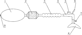
Accompanying drawing 1 is a structural representation of the present utility model.
Labelling in the accompanying drawing is represented respectively:
1, anesthesia air bag, 2, CO
2Absorber, 3, corrugated tubing, 4, bend pipe, 5, expiratory valve, 6, oxygen takes over, 7, bailout gas takes over, 8, breathing mask, 9, the anesthetis fill nipple.
The specific embodiment
Below in conjunction with accompanying drawing the reciprocal loop of anesthetis of the present utility model suction apparatus is done following detailed description the in detail.
As shown in Figure 1, the reciprocal loop of anesthetis of the present utility model suction apparatus, its structure comprises anesthesia air bag 1, corrugated tubing 3 and breathing mask 8, is connected with CO between anesthesia air bag 1 and the corrugated tubing 3
2Absorber 2, the other end of corrugated tubing 3 is connected with bend pipe 4, and bend pipe 4 ends are connected with breathing mask 8, are respectively arranged with expiratory valve 5 and oxygen on the bend pipe 4 and take over 6.Also be provided with bailout gas on the bend pipe 4 and take over 7.Anesthesia air bag 1 afterbody is provided with anesthetis fill nipple 9.
Claims (3)
1. the reciprocal loop of anesthetis suction apparatus comprises anesthesia air bag, corrugated tubing and breathing mask, it is characterized in that anaesthetizing between air bag and the corrugated tubing being connected with CO
2Absorber, the other end of corrugated tubing is connected with bend pipe, and the bend pipe end is connected with breathing mask, is respectively arranged with expiratory valve and oxygen on the bend pipe and takes over.
2. the reciprocal loop of anesthetis according to claim 1 suction apparatus is characterized in that also being provided with on the described bend pipe bailout gas and takes over.
3. the reciprocal loop of anesthetis according to claim 1 suction apparatus is characterized in that described anesthesia air bag afterbody is provided with the anesthetis fill nipple.
Priority Applications (1)
| Application Number | Priority Date | Filing Date | Title |
|---|---|---|---|
| CN2010201642493U CN201658728U (en) | 2010-04-21 | 2010-04-21 | Anesthetic reciprocating loop inhaling device |
Applications Claiming Priority (1)
| Application Number | Priority Date | Filing Date | Title |
|---|---|---|---|
| CN2010201642493U CN201658728U (en) | 2010-04-21 | 2010-04-21 | Anesthetic reciprocating loop inhaling device |
Publications (1)
| Publication Number | Publication Date |
|---|---|
| CN201658728U true CN201658728U (en) | 2010-12-01 |
Family
ID=43229136
Family Applications (1)
| Application Number | Title | Priority Date | Filing Date |
|---|---|---|---|
| CN2010201642493U Expired - Fee Related CN201658728U (en) | 2010-04-21 | 2010-04-21 | Anesthetic reciprocating loop inhaling device |
Country Status (1)
| Country | Link |
|---|---|
| CN (1) | CN201658728U (en) |
Cited By (1)
| Publication number | Priority date | Publication date | Assignee | Title |
|---|---|---|---|---|
| CN104548302A (en) * | 2014-12-02 | 2015-04-29 | 广西大学 | Inflation bag for containing desflurane |
-
2010
- 2010-04-21 CN CN2010201642493U patent/CN201658728U/en not_active Expired - Fee Related
Cited By (1)
| Publication number | Priority date | Publication date | Assignee | Title |
|---|---|---|---|---|
| CN104548302A (en) * | 2014-12-02 | 2015-04-29 | 广西大学 | Inflation bag for containing desflurane |
Similar Documents
| Publication | Publication Date | Title |
|---|---|---|
| CN204671697U (en) | Novel anesthetic gas machine | |
| CN201244267Y (en) | Cyclic closed device for respiration anesthesia | |
| CN205867254U (en) | Novel anesthesia machine that has disinfection function | |
| CN201658728U (en) | Anesthetic reciprocating loop inhaling device | |
| CN204219556U (en) | A kind of split-type breathes anesthesia outfit | |
| CN203123235U (en) | Pressurization type portable artificial respirator | |
| CN204073013U (en) | A kind of breathing circuit for anesthesia structure | |
| CN204655715U (en) | A kind of anesthetic ventilator | |
| CN203634609U (en) | Oxygen mask with oxygen bag | |
| CN201564928U (en) | Respiration device for rescuing infectious patient | |
| CN202951074U (en) | Artificial respirator for respiration medicine | |
| CN202961422U (en) | Respirator for cardiology department | |
| CN203043218U (en) | Artificial respirator for department of cardiology | |
| CN203954405U (en) | A kind of novel dual noinvasive Ventilation mask | |
| CN202105283U (en) | Oxygen inhaling nose stuffer | |
| CN203263975U (en) | Multifunctional laryngeal mask | |
| CN203468991U (en) | Novel artificial respiration device | |
| CN102488952A (en) | Double-airbag breathing apparatus | |
| CN209361599U (en) | CPAP pipeline locking cap | |
| CN207024364U (en) | A kind of portable severe first-aid respirator | |
| CN201070493Y (en) | Three-way pipe gas tube joint for breathing machine | |
| CN201426904Y (en) | Autogenous cutting oxygen storage breathing apparatus | |
| CN201959214U (en) | Novel artificial respirator | |
| CN201735034U (en) | Adapting interface from German standard oxygen terminal to Chinese standard oxygen terminal | |
| CN203123255U (en) | Clinical anaesthetic mask |
Legal Events
| Date | Code | Title | Description |
|---|---|---|---|
| C14 | Grant of patent or utility model | ||
| GR01 | Patent grant | ||
| C17 | Cessation of patent right | ||
| CF01 | Termination of patent right due to non-payment of annual fee |
Granted publication date: 20101201 Termination date: 20130421 |