CN201655657U - Outdoor vacuum circuit breaker - Google Patents
Outdoor vacuum circuit breaker Download PDFInfo
- Publication number
- CN201655657U CN201655657U CN201020147597XU CN201020147597U CN201655657U CN 201655657 U CN201655657 U CN 201655657U CN 201020147597X U CN201020147597X U CN 201020147597XU CN 201020147597 U CN201020147597 U CN 201020147597U CN 201655657 U CN201655657 U CN 201655657U
- Authority
- CN
- China
- Prior art keywords
- circuit breaker
- vacuum circuit
- operating mechanism
- outdoor vacuum
- actuating mechanism
- Prior art date
- Legal status (The legal status is an assumption and is not a legal conclusion. Google has not performed a legal analysis and makes no representation as to the accuracy of the status listed.)
- Expired - Fee Related
Links
Images
Landscapes
- Driving Mechanisms And Operating Circuits Of Arc-Extinguishing High-Tension Switches (AREA)
Abstract
The utility model discloses an outdoor vacuum circuit breaker, in particular to a new-generation large-volume outdoor vacuum circuit breaker, which has the advantages of small size, high performance, low power consumption and environmental protection and is provided with a spring permanent magnet optimized compound mechanism capable of realizing electric and manual division and combination. The outdoor vacuum circuit breaker mainly comprises an general actuating mechanism box, a transmission box, a mounting bracket, an upper and lower inlet/outlet terminal combination and three solid-sealed poles; wherein the general actuating mechanism box is formed by combining a buckle-free spring actuating mechanism and a permanent magnet actuating mechanism, and the three solid-sealed poles are vertically arranged on the general actuating mechanism box in parallel; and the transmission box is connected with the general actuating mechanism box, and the upper and lower inlet/outlet terminal combination is arranged on the three solid-sealed poles. The utility model has the advantages of long service life, no (little) maintenance, small size, low power consumption during operation (thereby directly improving the performance of the mechanism), multiple backup actuating performances and capability of avoiding (reducing) electrical accidents caused by product faults.
Description
Technical field
The utility model relates to circuit breaker, specifically a kind of outdoor vacuum circuit breaker.
Background technology
At domestic and international electrical network power station the more and more harsher performance requirement that the active service switch proposes (is especially required to possess simultaneously miniaturization, the big big capacity of electric current, the long-life, highly reliable, exempt from the switch of (lacking) maintainability), the switch of original design can not satisfy the requirement of modern electric.
The utility model content
(1) technical problem that will solve
The purpose of this utility model is the defective that exists at prior art, and a kind of outdoor vacuum circuit breaker is provided, and has solved the tall and big heaviness that prior art exists, high maintenance cost, low operation lifetime, the defective and the problem of no reserve actuating function.
(2) technical scheme
The technical scheme that its technical problem that solves the utility model adopts is: a kind of outdoor vacuum circuit breaker, its structure mainly comprise overall operating mechanism case, transmission case, mounting bracket, pass in and out line terminals combination and three poles up and down; Described overall operating mechanism case is to adopt the claspless spring operating mechanism to combine with permanent-magnet manipulating mechanism to form, and described three poles vertically are installed on the overall operation mechanism case side by side; Described transmission case is connected on the overall operating mechanism case, describedly passes in and out the line terminals aggregate erection up and down on three poles.
Described pole comprises the inlet wire conducting rod, go up vacuum interrupter that inlet wire conducting rod lower end connects, the silicon rubber full skirt of being flexible coupling of vacuum interrupter lower end, vacuum interrupter Soft Roll, epoxy resin human body, epoxy resin human body outer surface, outlet conducting rod external member and following outlet conducting rod external member down.
The insulated tension pole of described vacuum interrupter lower end by with transmission case in the branch modular converter that closes be connected again with operating mechanism in the overall operating mechanism case and link to each other.
Described transmission case comprise top close comprise in the sub-unit scalable tripping spring connected directed slide close branch connecting rod and connection thereof close branch conversion connecting lever.
Described spring operating mechanism and permanent-magnet manipulating mechanism comprise that a master closes the permanent magnet mechanism of branch and the spring operation means of connected claspless.
1. adopt three-phase under insulated tension pole, directly to set up the spring switching-off device, optimized the whole kinoplaszm amount of structure decrease, save unnecessary unnecessary object and participate in motion, reduce useless power consumption, more optimization and improvement switch just-off speed in the phase I.
2. adopting combined floodgate holding position direction and arc control device dynamic component to be subjected to force direction is that the arrangement of same center line and the big or small connecting lever that adds are combined into an angle of 90 degrees employing pulling force closing position snap close, make the operating mechanism of biconditional operation merit can drive bigger other load of more high power capacity level, employing is closed subangle and has also been made the whole actuating active power of raising switch more perfect less than the designs of 22 degree, and reduce the wearing and tearing of mechanical position, improved mechanical endurance.
3. adopted big or small connecting lever 90 degree to close the design that branch conversion combination comprises switching-off device, made pulling force combined floodgate connecting rod integral accounts for separating brake motion power as moving-mass very fraction well below the power consumption of old type switch before.
4. the new machinery combined floodgate permanent magnet mechanism device design that adopts permanent magnet mechanism to combine, closing by hand function that newly adds and motor combined floodgate two-way safeguarding function with spring operating mechanism make switch compare with operating reliability whole mechanical endurance the design before the switch of any way improved a grade.
(3) beneficial effect
A kind of outdoor vacuum circuit breaker of the present utility model is compared with prior art, has following beneficial effect:
1. realize the product long-life, exempt from (lacking) and safeguard;
2. realize product manufacturing miniaturization, reduce operation power consumption (directly improving mechanism performance);
3. realize how standby actuating function, avoid (minimizing) electric power accident because of the product bug development.
Description of drawings
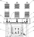
Fig. 1 is the structure left side pseudosection of a kind of outdoor vacuum circuit breaker of the present utility model;
Fig. 2 is the structural front view of a kind of outdoor vacuum circuit breaker of the present utility model;
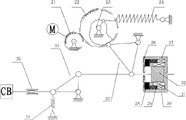
Fig. 3 is the global design scheme principle sketch of a kind of outdoor vacuum circuit breaker of the present utility model.
Among the figure: 1, pass in and out the line terminals combination up and down; 2, vacuum interrupter; 3, be flexible coupling; 4, insulated tension pole; 5, close branch connecting lever conversion combination; 6, separating brake composite set; 7, combined floodgate connects combination; 8, combination actuator; 9, pole; 10, go up input terminal; 11, the spacing buffering combination of separating brake; 12, insulated tension pole; 13, transmission macro-axis; 14, close branch and connect combination; 15, the electric combination of switch state; 16, secondary control outlet connector; 17, sub-unit is closed on top; 18, mounting bracket; 19, overall operating mechanism case;
21, energy storage pinion; 22, energy storage gear wheel; 23, output cam; 24, energy-stored spring; 25, combined floodgate output toggle arm; 26, permanent magnet mechanism baffle plate; 27, permanent magnet mechanism yoke; 28, insulated ring; 29, permanent magnet; 30, permanent magnetism switching winding; 31, permanent magnetism closing coil; 32, iron core; 33, close the branch connecting lever; 34, tripping spring; 35, sliding connection block.
Embodiment
Next explain below with reference to Figure of description a kind of outdoor vacuum circuit breaker of the present utility model being done.
A kind of outdoor vacuum circuit breaker, its structure mainly comprise overall operating mechanism case 19, transmission case, mounting bracket 18, pass in and out 1 and three pole 9 of line terminals combination up and down; Described overall operating mechanism case is to adopt the claspless spring operating mechanism to combine with permanent-magnet manipulating mechanism to form, and described three poles vertically are installed on the overall operation mechanism case 19 side by side; Described transmission case is connected on the overall operating mechanism case, describedly passes in and out line terminals combination 1 up and down and is installed on three poles 9.Realize that the branch that closes of global switch realizes functions such as protection, switching, contact to power circuit.
Described pole comprises the inlet wire conducting rod, go up vacuum interrupter 2 that inlet wire conducting rod lower end connects, the vacuum interrupter lower end be flexible coupling 3, the silicon rubber full skirt of vacuum interrupter Soft Roll, epoxy resin human body, epoxy resin human body outer surface, outlet conducting rod external member and following outlet conducting rod external member down.
The insulated tension pole of described vacuum interrupter lower end by with transmission case in the branch modular converter that closes be connected again with operating mechanism in the overall operating mechanism case and link to each other.
Described transmission case comprise top close comprise in the sub-unit scalable tripping spring connected directed slide close branch connecting rod and connection thereof close branch conversion connecting lever.Close among sub-module and scalable separating brake assembly such as Fig. 3 13 to 15 all interior unit constructions in the described transmission case.
Described spring operating mechanism and permanent-magnet manipulating mechanism comprise that a master closes the permanent magnet mechanism of branch and the spring operation means of connected claspless.As all parts in 1 to 12 among Fig. 3.
The above embodiment is a kind of of the more preferably concrete execution mode of the utility model, and common variation that those skilled in the art carries out in the technical solutions of the utility model scope and replacement all should be included in the protection range of the present utility model.
Claims (5)
1. outdoor vacuum circuit breaker, its structure mainly comprise overall operating mechanism case, transmission case, mounting bracket, pass in and out line terminals combination and three poles up and down; It is characterized in that: described overall operating mechanism case is to adopt the claspless spring operating mechanism to combine with permanent-magnet manipulating mechanism to form, and described three poles vertically are installed on the overall operation mechanism case side by side; Described transmission case is connected on the overall operating mechanism case, describedly passes in and out the line terminals aggregate erection up and down on three poles.
2. a kind of outdoor vacuum circuit breaker according to claim 1 is characterized in that: described pole comprises the inlet wire conducting rod, go up vacuum interrupter that inlet wire conducting rod lower end connects, the silicon rubber full skirt of being flexible coupling of vacuum interrupter lower end, vacuum interrupter Soft Roll, epoxy resin human body, epoxy resin human body outer surface, outlet conducting rod external member and following outlet conducting rod external member down.
3. a kind of outdoor vacuum circuit breaker according to claim 2 is characterized in that: the insulated tension pole of described vacuum interrupter lower end by with transmission case in the branch modular converter that closes be connected again with operating mechanism in the overall operating mechanism case and link to each other.
4. a kind of outdoor vacuum circuit breaker according to claim 1 and 2 is characterized in that: described transmission case comprise top close comprise in the sub-unit scalable tripping spring connected directed slide close branch connecting rod and connection thereof close branch conversion connecting lever.
5. a kind of outdoor vacuum circuit breaker according to claim 1 and 2 is characterized in that: described spring operating mechanism and permanent-magnet manipulating mechanism comprise that a master closes the permanent magnet mechanism of branch and the spring operation means of connected claspless.
Priority Applications (1)
| Application Number | Priority Date | Filing Date | Title |
|---|---|---|---|
| CN201020147597XU CN201655657U (en) | 2010-04-01 | 2010-04-01 | Outdoor vacuum circuit breaker |
Applications Claiming Priority (1)
| Application Number | Priority Date | Filing Date | Title |
|---|---|---|---|
| CN201020147597XU CN201655657U (en) | 2010-04-01 | 2010-04-01 | Outdoor vacuum circuit breaker |
Publications (1)
| Publication Number | Publication Date |
|---|---|
| CN201655657U true CN201655657U (en) | 2010-11-24 |
Family
ID=43120901
Family Applications (1)
| Application Number | Title | Priority Date | Filing Date |
|---|---|---|---|
| CN201020147597XU Expired - Fee Related CN201655657U (en) | 2010-04-01 | 2010-04-01 | Outdoor vacuum circuit breaker |
Country Status (1)
| Country | Link |
|---|---|
| CN (1) | CN201655657U (en) |
Cited By (6)
| Publication number | Priority date | Publication date | Assignee | Title |
|---|---|---|---|---|
| CN102789924A (en) * | 2011-05-20 | 2012-11-21 | 湖南丰日电源电气股份有限公司 | Intelligent outdoor on-pole vacuum circuit breaker |
| CN104576180A (en) * | 2014-12-31 | 2015-04-29 | 安徽宇腾真空电气有限责任公司 | Permanent magnetic mechanism circuit breaker |
| CN104599896A (en) * | 2014-12-31 | 2015-05-06 | 安徽宇腾真空电气有限责任公司 | Horizontal permanent magnetic mechanism circuit breaker |
| CN104599898A (en) * | 2014-12-31 | 2015-05-06 | 安徽宇腾真空电气有限责任公司 | Horizontal permanent magnetic mechanism breaker |
| CN105161352A (en) * | 2015-09-23 | 2015-12-16 | 陕西西高开关有限责任公司 | Novel high-voltage circuit breaker |
| CN109416997A (en) * | 2016-06-27 | 2019-03-01 | Abb瑞士股份有限公司 | Middle piezoelectricity way switch or medium voltage breaker |
-
2010
- 2010-04-01 CN CN201020147597XU patent/CN201655657U/en not_active Expired - Fee Related
Cited By (8)
| Publication number | Priority date | Publication date | Assignee | Title |
|---|---|---|---|---|
| CN102789924A (en) * | 2011-05-20 | 2012-11-21 | 湖南丰日电源电气股份有限公司 | Intelligent outdoor on-pole vacuum circuit breaker |
| CN104576180A (en) * | 2014-12-31 | 2015-04-29 | 安徽宇腾真空电气有限责任公司 | Permanent magnetic mechanism circuit breaker |
| CN104599896A (en) * | 2014-12-31 | 2015-05-06 | 安徽宇腾真空电气有限责任公司 | Horizontal permanent magnetic mechanism circuit breaker |
| CN104599898A (en) * | 2014-12-31 | 2015-05-06 | 安徽宇腾真空电气有限责任公司 | Horizontal permanent magnetic mechanism breaker |
| CN105161352A (en) * | 2015-09-23 | 2015-12-16 | 陕西西高开关有限责任公司 | Novel high-voltage circuit breaker |
| CN109416997A (en) * | 2016-06-27 | 2019-03-01 | Abb瑞士股份有限公司 | Middle piezoelectricity way switch or medium voltage breaker |
| CN109416997B (en) * | 2016-06-27 | 2020-03-31 | Abb瑞士股份有限公司 | Medium-voltage circuit switch or medium-voltage circuit breaker |
| US10714274B2 (en) | 2016-06-27 | 2020-07-14 | Abb Schweiz Ag | Medium voltage circuit switch or breaker |
Similar Documents
| Publication | Publication Date | Title |
|---|---|---|
| CN201655657U (en) | Outdoor vacuum circuit breaker | |
| CN101533736B (en) | Small spring operating mechanism for vacuum load switch or vacuum breaker | |
| CN101877289B (en) | Seal vacuum circuit breaker of outdoor high-voltage permanent-magnetic mechanism | |
| CN202034297U (en) | Outdoor high-pressure permanent-magnet vacuum circuit breaker | |
| CN101807487B (en) | Permanent magnet high-voltage vacuum circuit breaker | |
| CN202495384U (en) | Indoor side mounted solid sealed pole vacuum circuit breaker | |
| CN102426975A (en) | Permanent magnetic operation mechanism | |
| CN201732720U (en) | Permanent-magnet high-voltage vacuum circuit breaker | |
| CN201732722U (en) | Indoor permanent magnetic seal high-voltage vacuum breaker | |
| CN201673852U (en) | Outdoor high-voltage solidified vacuum circuit breaker with permanent magnet mechanism | |
| CN204884994U (en) | Vacuum permanent magnetism circuit breaker | |
| CN201112263Y (en) | High voltage vacuum breaker | |
| CN212517024U (en) | Quick-acting magnetic control vacuum circuit breaker | |
| CN205230925U (en) | Transformer substation is with controlling vacuum circuit breaker mutually | |
| CN202339884U (en) | Permanent operating mechanism | |
| CN101814393A (en) | Vacuum contactor with mixed magnetic field | |
| CN110718411B (en) | Can save space's box-type circuit breaker altogether | |
| CN201387840Y (en) | Spring operating mechanism for miniature vacuum load switch or vacuum circuit breaker | |
| CN102683097A (en) | Multi-station combination outdoor vacuum switch device | |
| CN103280373B (en) | Permanent magnetism in outdoor three-phase column vacuum breaker and spring dual operation mechanisms | |
| CN202394795U (en) | Indoor solid-sealed pole type vacuum breaker | |
| CN209087689U (en) | Intelligent outdoor high-voltage vacuum breaker with conduit connection row's protective device | |
| CN202394799U (en) | Solid-sealed type vacuum circuit breaker | |
| CN201918308U (en) | Solid-sealed vacuum circuit breaker | |
| CN205487932U (en) | Outdoor interchange high pressure permanent magnetism vacuum circuit breaker |
Legal Events
| Date | Code | Title | Description |
|---|---|---|---|
| C14 | Grant of patent or utility model | ||
| GR01 | Patent grant | ||
| C17 | Cessation of patent right | ||
| CF01 | Termination of patent right due to non-payment of annual fee |
Granted publication date: 20101124 Termination date: 20130401 |