CN201652566U - An asymmetric series heating device - Google Patents
An asymmetric series heating device Download PDFInfo
- Publication number
- CN201652566U CN201652566U CN2010201864639U CN201020186463U CN201652566U CN 201652566 U CN201652566 U CN 201652566U CN 2010201864639 U CN2010201864639 U CN 2010201864639U CN 201020186463 U CN201020186463 U CN 201020186463U CN 201652566 U CN201652566 U CN 201652566U
- Authority
- CN
- China
- Prior art keywords
- heating
- series
- unit
- utility
- heating unit
- Prior art date
- Legal status (The legal status is an assumption and is not a legal conclusion. Google has not performed a legal analysis and makes no representation as to the accuracy of the status listed.)
- Expired - Fee Related
Links
- 238000010438 heat treatment Methods 0.000 title claims abstract description 93
- 238000000605 extraction Methods 0.000 claims abstract description 23
- XLYOFNOQVPJJNP-UHFFFAOYSA-N water Substances O XLYOFNOQVPJJNP-UHFFFAOYSA-N 0.000 abstract description 15
- 238000010248 power generation Methods 0.000 abstract description 2
- 238000010586 diagram Methods 0.000 description 4
- 238000000034 method Methods 0.000 description 2
- 230000009286 beneficial effect Effects 0.000 description 1
- 238000005516 engineering process Methods 0.000 description 1
Images


Landscapes
- Steam Or Hot-Water Central Heating Systems (AREA)
Abstract
本实用新型公开了属于能源技术领域的能够使供热机组供热抽汽压力降低的一种非对称式串联供热装置。两台供热机组的供热抽汽控制阀各连接一台热网加热器,两台热网加热器为非对称式串联。本实用新型采用非对称式串联供热装置降低供热机组的供热抽汽压力,实现对循环水的逐级加热,能量的梯级利用,与常规的并联布置方式相比,在供热量相同的情况下,能够提高循环水出口温度;降低第一供热机组的供热抽汽压力,这样大大降低了供热机组的供热抽汽压力,提高了机组的发电量,在供热量相同的情况下,可以多发电,增加热电厂的经济效益。
The utility model discloses an asymmetrical series heating device which belongs to the technical field of energy and can reduce the pressure of heating and extracting steam of a heating unit. The heating and extraction control valves of the two heating units are connected to a heating network heater respectively, and the two heating network heaters are asymmetrically connected in series. The utility model adopts an asymmetrical series heating device to reduce the heat supply and steam extraction pressure of the heating unit, realize the step-by-step heating of the circulating water, and use the energy in steps. Compared with the conventional parallel arrangement, the utility model has the same heat supply Under the circumstances, the outlet temperature of the circulating water can be increased; the heating and extraction pressure of the first heating unit can be reduced, which greatly reduces the heating and extraction pressure of the heating unit and increases the power generation of the unit. Under certain circumstances, more power can be generated and the economic benefits of thermal power plants can be increased.
Description
技术领域technical field
本实用新型属于能源技术领域。特别涉及能够使供热机组供热抽汽压力降低的一种非对称式串联供热装置。The utility model belongs to the field of energy technology. In particular, it relates to an asymmetric series heating device capable of reducing the pressure of heating and extracting steam of a heating unit.
背景技术Background technique
目前国内供热机组布置特点主要是作为供热装置的热网加热器并联布置,在两台供热装置(热网加热器)并联布置系统中,每台供热机组的供热抽汽带一台供热装置,如图1所示的并联布置方式供热装置的示意图,第二级热网加热器3和第一级热网加热器4并联。在两台供热装置并联运行时,两台供热机组对两台供热装置相互之间没有影响,每台供热机组的供热抽汽参数相同,抽汽压力相同,对循环水的加热温度一样,但是对要求提供温度比较高的热水,则要求供热机组的供热抽汽压力比较高。还有一种布置方式是串联布置,即两台供热装置串联布置,其中,每台供热机组的供热抽汽带一台供热装置,但是对循环水的加热温度不一样,是逐级加热,能量的梯级利用,可以提供温度比较高的热水。At present, the layout of domestic heating units is mainly characterized by the parallel arrangement of heating network heaters as heating devices. In the parallel arrangement system of two heating devices (heating network heaters), the heating and extraction of each heating unit takes A heat supply device, a schematic diagram of a parallel arrangement heating device as shown in Figure 1, the second-stage
实用新型内容Utility model content
本实用新型的目的是针对现有技术中采用两台供热装置并联布置方式,对要求提供温度比较高的热水,供热机组的供热抽汽压力则比较高的不足而提供一种非对称式串联供热装置,其特征在于,两台供热机组的供热抽汽控制阀各连接一台热网加热器,两台热网加热器串联。The purpose of this utility model is to provide a non-standard heating system for the prior art that adopts the parallel arrangement of two heating devices to provide hot water with a relatively high temperature, and the heating and extraction pressure of the heating unit is relatively high. The symmetrical series heating device is characterized in that the heating extraction control valves of the two heating units are respectively connected to a heating network heater, and the two heating network heaters are connected in series.
所述两台热网加热器串联为非对称式串联,即两台供热机组所带热网加热器的换热面积不一样,其他结构参数相同。The two heating network heaters are connected in asymmetrical series connection, that is, the heat exchange areas of the heating network heaters of the two heating units are different, and other structural parameters are the same.
本实用新型的有益效果是非对称式串联供热装置降低供热机组的供热抽汽压力,实现对循环水的逐级加热,能量的梯级利用,与常规的并联布置方式相比,在供热量相同的情况下,能够提高循环水出口温度;并且适当增加第一供热机组所带第二级热网加热器的面积,降低第一供热机组的供热抽汽压力,这样大大降低了供热机组的供热抽汽压力,提高了机组的发电量,在供热量相同的情况下,可以多发电,增加热电厂的经济效益。The beneficial effect of the utility model is that the asymmetric series heating device reduces the heating and extraction pressure of the heating unit, realizes the step-by-step heating of the circulating water, and uses the energy in steps. In the case of the same quantity, the outlet temperature of circulating water can be increased; and the area of the second-stage heat network heater carried by the first heating unit can be appropriately increased to reduce the heating and extraction pressure of the first heating unit, which greatly reduces the The heat supply and steam extraction pressure of the heating unit increases the power generation of the unit. Under the same heat supply, it can generate more power and increase the economic benefits of the thermal power plant.
附图说明Description of drawings
图1为并联布置方式供热装置的示意图。Fig. 1 is a schematic diagram of a heating device arranged in parallel.
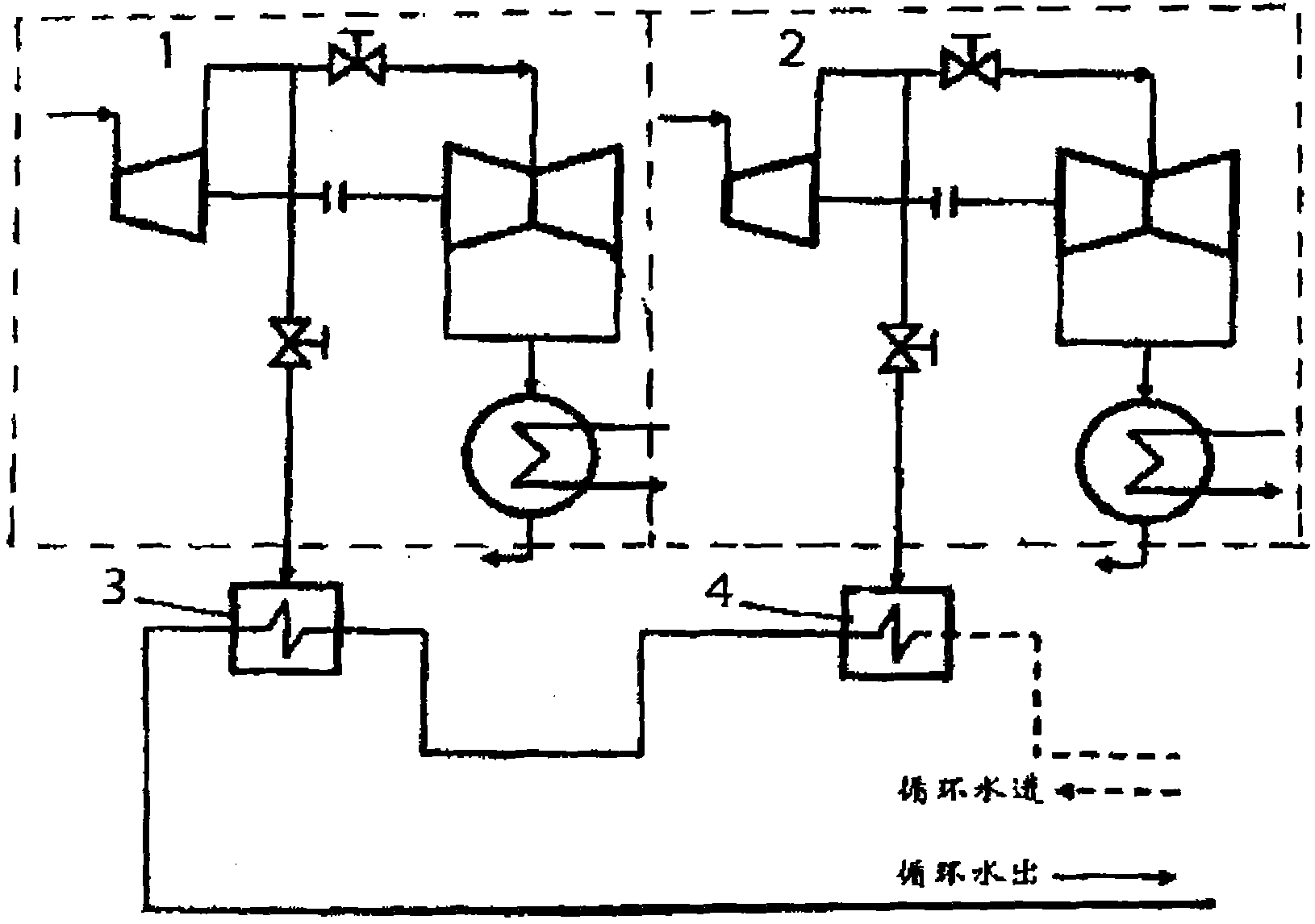
图2为串联布置方式供热装置的示意图。Fig. 2 is a schematic diagram of a heating device arranged in series.
图中符号:Symbols in the figure:
1-第一供热机组;2-第二供热机组;3-第二级热网加热器;4-第一级热网加热器。1-First heating unit; 2-Second heating unit; 3-Second stage heating network heater; 4-First stage heating network heater.
具体实施方式Detailed ways
本实用新型提供一种非对称式串联供热装置。下面结合附图和实例对本实用新型进行说明。The utility model provides an asymmetric series heating device. Below in conjunction with accompanying drawing and example the utility model is described.
图2所示为串联布置方式供热装置的示意图。第一供热机组的供热抽汽控制阀连接第二级热网加热器3第二供热机组2的供热抽汽控制阀连接第一级热网加热器4,第二级热网加热器3和第一级热网加热器4进行非对称式串联。所述两台热网加热器串联为非对称式串联,即两台供热机组所带热网加热器的换热面积不一样,其他结构参数相同,一台供热机组所带的第二级热网加热器的换热面积比另一台供热机组所带第一级热网加热器的换热面积大,增加了第二级热网加热器的传热性能,使第二级热网加热器加热热网水所需的抽汽压力降低Figure 2 is a schematic diagram of a heating device arranged in series. The heat supply and extraction control valve of the first heating unit is connected to the second-stage
所述供热装置的运行流程如下,以200MW供热机组为例:The operation process of the heating device is as follows, taking a 200MW heating unit as an example:
如果采用并联的供热模式,结合图1,每台热网加热器的水量为528kg/s,进口温度为70℃,出口温度为125℃,每台供热机组的供热抽汽压力为0.33MPa,流量360t/h。If the parallel heating mode is used, referring to Figure 1, the water volume of each heating network heater is 528kg/s, the inlet temperature is 70°C, the outlet temperature is 125°C, and the heating and extraction pressure of each heating unit is 0.33 MPa, flow rate 360t/h.
如果采用串联的供热模式,热网供、回水温度为125/70℃时,结合图2,与第二供热机组连接的第一级热网加热器4的循环水量为1056kg/s,循环水进口温度为70℃,出口温度为97.5℃,第一级供热机组抽汽压力为0.21MPa,流量360t/h;与第一供热机组连接的第二级热网加热器3的循环水量1056kg/s,进口温度为97.5℃,出口温度为125℃,第一级供热机组抽汽压力为0.33MPa,流量360t/h。If the heating mode in series is adopted, when the heating network supply and return water temperature is 125/70°C, referring to Figure 2, the circulating water volume of the first stage
Claims (2)
Priority Applications (1)
| Application Number | Priority Date | Filing Date | Title |
|---|---|---|---|
| CN2010201864639U CN201652566U (en) | 2010-05-04 | 2010-05-04 | An asymmetric series heating device |
Applications Claiming Priority (1)
| Application Number | Priority Date | Filing Date | Title |
|---|---|---|---|
| CN2010201864639U CN201652566U (en) | 2010-05-04 | 2010-05-04 | An asymmetric series heating device |
Publications (1)
| Publication Number | Publication Date |
|---|---|
| CN201652566U true CN201652566U (en) | 2010-11-24 |
Family
ID=43117805
Family Applications (1)
| Application Number | Title | Priority Date | Filing Date |
|---|---|---|---|
| CN2010201864639U Expired - Fee Related CN201652566U (en) | 2010-05-04 | 2010-05-04 | An asymmetric series heating device |
Country Status (1)
| Country | Link |
|---|---|
| CN (1) | CN201652566U (en) |
Cited By (3)
| Publication number | Priority date | Publication date | Assignee | Title |
|---|---|---|---|---|
| CN102287870A (en) * | 2011-06-01 | 2011-12-21 | 山东泓奥电力科技有限公司 | Device of transformation of straight condensing unit into heat supply unit for improving heat supply economical effect |
| CN105065071A (en) * | 2015-09-25 | 2015-11-18 | 东方电气集团东方汽轮机有限公司 | High-pressure heat supply method for thermal power plant |
| CN111678187A (en) * | 2020-05-23 | 2020-09-18 | 中国大唐集团科学技术研究院有限公司火力发电技术研究院 | Double-machine back pressure flexible heat supply system with heat storage tank and method |
-
2010
- 2010-05-04 CN CN2010201864639U patent/CN201652566U/en not_active Expired - Fee Related
Cited By (3)
| Publication number | Priority date | Publication date | Assignee | Title |
|---|---|---|---|---|
| CN102287870A (en) * | 2011-06-01 | 2011-12-21 | 山东泓奥电力科技有限公司 | Device of transformation of straight condensing unit into heat supply unit for improving heat supply economical effect |
| CN105065071A (en) * | 2015-09-25 | 2015-11-18 | 东方电气集团东方汽轮机有限公司 | High-pressure heat supply method for thermal power plant |
| CN111678187A (en) * | 2020-05-23 | 2020-09-18 | 中国大唐集团科学技术研究院有限公司火力发电技术研究院 | Double-machine back pressure flexible heat supply system with heat storage tank and method |
Similar Documents
| Publication | Publication Date | Title |
|---|---|---|
| CN104121047A (en) | Thermal power plant heat supply and steam extraction overbottom pressure utilization system with back pressure turbine | |
| CN202734015U (en) | Rough vacuum circulating water heat supply system of thermal power plant | |
| CN204404312U (en) | The heat network system of efficiency utilization steam power plant heating steam | |
| CN203464249U (en) | Condensed water heat regenerative system with absorption heat pump | |
| CN105956732A (en) | Energy saving amount calculating method after replacing electric pump by steam pump for circulating water of heat supply network | |
| CN204404316U (en) | A kind of high-efficiency multi-stage heat supply network heating system of applicable Air-cooled Unit steam power plant | |
| CN206345827U (en) | A kind of crude distillation tower top WHRS | |
| CN201652566U (en) | An asymmetric series heating device | |
| CN101881190A (en) | System for supplying heat and heating condensate water by extracting residual heat of power plant through heat pump | |
| CN204612228U (en) | A kind of low temperature heat system | |
| CN108361797A (en) | A kind of high-temperature heat accumulation type power peak regulation cogeneration of heat and power waste-heat recovery device and method | |
| CN104100313A (en) | Thermal power plant heat supply extraction steam residual pressure utilization system adopting back pressure extraction turbine | |
| CN207960696U (en) | A kind of micro- thermal process again of steam turbine and implementation system | |
| CN103759316A (en) | Cascade heating system for heat supply network circulation water | |
| CN213300193U (en) | Steam turbine set heat utilization system | |
| CN204461025U (en) | A kind of heat-conducting oil heating system utilizing synthetic leather baking oven waste heat | |
| CN202253581U (en) | Energy-saving softened water heating device for thermal power plant | |
| CN101881437A (en) | System for heating condensate water by extracting residual heat of power plant through heat pump | |
| CN205579710U (en) | Heat pump municipal heating systems heating system is united to low vacuum | |
| CN205156097U (en) | Novel recirculated cooling water water supply system | |
| CN204691834U (en) | A kind of energy-saving and emission-reduction system utilizing low-grade extraction for heat supply | |
| CN205316925U (en) | Steam heat transfer device | |
| CN211176872U (en) | Multipurpose flue gas waste heat recovery device for thermal power plant | |
| CN204717665U (en) | A kind of double reheat power generation sets economizer variable area bootstrap system | |
| CN203174081U (en) | Plate type heat exchanger for vinegar making |
Legal Events
| Date | Code | Title | Description |
|---|---|---|---|
| C14 | Grant of patent or utility model | ||
| GR01 | Patent grant | ||
| CF01 | Termination of patent right due to non-payment of annual fee |
Granted publication date: 20101124 Termination date: 20150504 |
|
| EXPY | Termination of patent right or utility model |