CN201629184U - Photoelectric composite sea power cable - Google Patents
Photoelectric composite sea power cable Download PDFInfo
- Publication number
- CN201629184U CN201629184U CN2010201430860U CN201020143086U CN201629184U CN 201629184 U CN201629184 U CN 201629184U CN 2010201430860 U CN2010201430860 U CN 2010201430860U CN 201020143086 U CN201020143086 U CN 201020143086U CN 201629184 U CN201629184 U CN 201629184U
- Authority
- CN
- China
- Prior art keywords
- power cable
- steel wire
- core
- conductor
- layer
- Prior art date
- Legal status (The legal status is an assumption and is not a legal conclusion. Google has not performed a legal analysis and makes no representation as to the accuracy of the status listed.)
- Expired - Lifetime
Links
Images


Abstract
A photoelectric composite sea power cable comprises cores (1), shield layers (2), insulation layers (3), insulator shield layers and inner protective layers (4), an armor inner cushion (5), an armor layer (6) and an armor outer protective layer (7). Optical fiber units (A) consists of the cores (1), the shield layers (2), the insulation layers (3) and the insulator shield layers and inner protective layers (4) which are sequentially arranged from inside to outside; and three groups of the optical fiber units (A) are mutually overlapped together. The sea power cable is characterized in that each core (1) consists of a steel wire lead and an aluminum lead; the steel wire lead is positioned in the middle of the core (1); and the steel wire lead and the aluminum lead jointly wind to form the core (1) formed by a steel core aluminum winding wire structure. Compared with the prior art, the sea power cable with the structure has the advantages that copper is replaced by aluminum to save cost and lead conductivity to completely conform to standards, and the winding wire by winding the steel wire lead with the aluminum lead can freely compensate shortage of insufficient tensile strength of the aluminum lead. The sea power cable reduces production cost, and conforms to required standards of the conductivity and tensile strength.
Description
Technical field
The utility model relates to a kind of submarine cable technical field that is used for, and especially refers to the sea electric power cable that a kind of sea floor optoelectronic is compound.
Background technology
Existing a kind of patent No. discloses a kind of structure for the Chinese utility model patent that the CN200820034047.X name is called " seabed fiber compound power cable ", its structure comprises conductor, insulating barrier, water blocking layer, metal sheath layer, inner restrictive coating, inner cushion layer, external sheath layer, armour, serving, be outside equipped with insulating barrier at conductor, be outside equipped with water blocking layer at insulating barrier, be outside equipped with metal sheath layer at water blocking layer, be outside equipped with inner restrictive coating at metal sheath layer; The sea electric power cable most external is a serving, and armour is housed in the serving, and armour adopts steel wire, and inner cushion layer is housed in the armour; Device has the seabed fiber unit in the power cable core gap, seabed in inner cushion layer.But its shortcoming is conductor not to be improved, the conductor of this cable mostly adopts copper, because of copper had both satisfied good electrical conductivity, can satisfy cable again and have enough tensile strength, but,, and adopt other material not enough because of tensile strength so cost of manufacture is higher because of copper price height, therefore develop and a kind ofly can satisfy good electrical conductivity, the submarine cable that has enough tensile strength again is ready-made to be the interesting gesture of a kind of development.
Summary of the invention
Technical problem to be solved in the utility model is to provide at above-mentioned prior art present situation that a kind of cost of manufacture is low, cable tensile strength reaches the compound sea electric power cable of the qualified photoelectricity of conductivity greatly.
The utility model solves the problems of the technologies described above the technical scheme that is adopted: the sea electric power cable that this photoelectricity is compound; include core; screen; insulating barrier; insulator screen and sheath; the armouring inner cushion layer; armour and armouring external protection; described core; screen; insulating barrier; insulator screen and sheath set gradually the fiber unit that forms from the inside to the outside; described fiber unit has three groups also to stack together mutually; described armouring inner cushion layer; armour and armouring external protection are wrapped in three groups of fiber units the inside from the inside to the outside successively; the space is provided with filler between three groups of fiber units and armouring inner cushion layer; it is characterized in that: described core is made up of steel wire lead and aluminum conductor; described steel wire lead is positioned at the center of core, and steel wire lead and aluminum conductor are the formed core of steel reinforced aluminium conductor structure.
As improvement, described steel reinforced aluminium conductor structure is meant: some strands of steel wire leads are positioned at the center, and some strands of aluminum conductors are outside the steel wire lead and be twisted into the steel reinforced aluminium conductor conductor mutually.
As improvement, described screen comprises semi-conductor electricity band and conductor shield, and core is wrapped in the semi-conductor electricity band, and the semi-conductor electricity band is wrapped in the conductor shield.
Improve again, described insulator screen comprises insulation screen, semiconductive water-blocking buffer layer, copper strips lapping layer, semiconductive water-blocking buffer layer, and described sheath comprises plumbous cover and insulation inner cushion layer, and arrangement position is for being followed successively by insulation screen, semiconductive water-blocking buffer layer, copper strips lapping layer, semiconductive water-blocking buffer layer, plumbous cover and insulation inner cushion layer from the inside to the outside.
Improve, described armouring inner cushion layer is preferably the pitch inner cushion layer of polypropylene rope as inner reinforcement again.
Improve, described armouring external protection can be the pitch outer wrapping layer of polypropylene rope as inner reinforcement again.
Improve, described armour is made up of many galvanized steel wire ropes again, and described galvanized steel wire rope is positioned at the structure of same periphery distribution with cross section and the protective layer that forms.
Improve, described filler can be the poly-third ethene rope again.
Compared with prior art, the utility model adopts core to be made up of steel wire lead and aluminum conductor, and described steel wire lead is positioned at the center of core, and steel wire lead and aluminum conductor are twisted into the formed core of steel reinforced aluminium conductor structure jointly.The advantage of this structure is, replaced copper by aluminium, not only provide cost savings, and the also complete conformance with standard of conductivity, and the twisted wire of the strand of steel wire lead wherein aluminum conductor, can exempt to mend the problem of aluminum conductor tensile strength deficiency again, so the cable that the utility model is made had both reduced production cost, and conductivity and tensile strength standard all up to specification.
Description of drawings
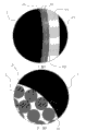
Fig. 1 is the structural representation of the utility model embodiment;
Fig. 2 is the structure for amplifying schematic diagram of fiber unit A among Fig. 1;
Fig. 3 is the enlarged drawing of I portion among Fig. 2;
Fig. 4 is the enlarged drawing of II portion among Fig. 2;
Fig. 5 is the cutaway view of the recombination line cross section of steel wire alclad among Fig. 1.
Embodiment
Embodiment describes in further detail the utility model below in conjunction with accompanying drawing.
As Fig. 1; Fig. 3; Fig. 4 and shown in Figure 5; the sea electric power cable that the photoelectricity of present embodiment is compound; include core 1; screen 2; insulating barrier 3; insulator screen and sheath 4; armouring inner cushion layer 5; armour 6 and armouring external protection 7; described core 1; screen 2; insulating barrier 3; insulator screen and sheath 4 set gradually the fiber unit A that forms from the inside to the outside; described fiber unit A has three groups also to stack together mutually; described armouring inner cushion layer 5; armour 6 and armouring external protection 7 are wrapped in three groups of fiber unit A the inside from the inside to the outside successively; the space is provided with filler 8 between three groups of fiber unit A and armouring inner cushion layer 5, and filler 8 is the poly-third ethene rope.Core 1 is that wherein steel wire lead 11 is positioned at the center of core 1 by the mutual stranded conductor that forms of blend of many aluminum conductors with the steel wire lead 11 strand aluminum conductors 12 that can increase cable tensile strength.Above-mentioned screen 2 comprises semi-conductor electricity band 22 and conductor shield 21, sees shown in Figure 4ly, and core 1 is wrapped in the semi-conductor electricity band 22, and semi-conductor electricity band 22 is wrapped in the conductor shield 21.And
Above-mentioned insulator screen comprises insulation screen 41, semiconductive water-blocking buffer layer 42, copper strips lapping layer 43, semiconductive water-blocking buffer layer 42, and described sheath 4 comprises plumbous cover 44 and insulation inner cushion layer 45, and arrangement position is for being followed successively by insulation screen 41, semiconductive water-blocking buffer layer 42, copper strips lapping layer 43, semiconductive water-blocking buffer layer 42, plumbous cover 44 and insulation inner cushion layer 45 from the inside to the outside.
See 2 and shown in Figure 3.And armouring inner cushion layer 5 is the pitch inner cushion layer of polypropylene rope as inner reinforcement; and the armouring external protection is the pitch outer wrapping layer of polypropylene rope as inner reinforcement; described armour 6 is made up of many galvanized steel wire ropes 61, and described galvanized steel wire rope 61 is positioned at the structure that same periphery distributes and the protective layer that forms with cross section.
Claims (8)
1. sea electric power cable that photoelectricity is compound; include core (1); screen (2); insulating barrier (3); insulator screen and sheath (4); armouring inner cushion layer (5); armour (6) and armouring external protection (7); described core (1); screen (2); insulating barrier (3); insulator screen and sheath (4) set gradually the fiber unit (A) that forms from the inside to the outside; described fiber unit (A) has three groups also to stack together mutually; described armouring inner cushion layer (5); armour (6) and armouring external protection (7) are wrapped in three groups of fiber units (A) the inside from the inside to the outside successively; the space is provided with filler (8) between three groups of fiber units (A) and armouring inner cushion layer (5); it is characterized in that: described core (1) is made up of steel wire lead and aluminum conductor; described steel wire lead is positioned at the center of core (1), and steel wire lead and aluminum conductor are the formed core of steel reinforced aluminium conductor structure (1).
2. according to the described power cable that is used for the seabed of claim 1, it is characterized in that: described steel reinforced aluminium conductor structure is meant: some strands of steel wire leads are positioned at the center, and some strands of aluminum conductors are outside the steel wire lead and be twisted into the steel reinforced aluminium conductor conductor mutually.
3. power cable according to claim 1, it is characterized in that: described screen (2) comprises semi-conductor electricity band (22) and conductor shield (21), core (1) is wrapped in the semi-conductor electricity band (22), and semi-conductor electricity band (22) is wrapped in the conductor shield (21).
4. power cable according to claim 1, it is characterized in that: described insulator screen comprises insulation screen (41), semiconductive water-blocking buffer layer (42), copper strips lapping layer (43), semiconductive water-blocking buffer layer (42), and described sheath (4) comprises plumbous cover (44) and insulation inner cushion layer (45), and arrangement position is for being followed successively by insulation screen (41), semiconductive water-blocking buffer layer (42), copper strips lapping layer (43), semiconductive water-blocking buffer layer (42), plumbous cover (44) and insulation inner cushion layer (45) from the inside to the outside.
5. power cable according to claim 1 is characterized in that: described armouring inner cushion layer (5) is the pitch inner cushion layer of polypropylene rope as inner reinforcement.
6. power cable according to claim 1 is characterized in that: described armouring external protection is the pitch outer wrapping layer of polypropylene rope as inner reinforcement.
7. according to the described power cable that is used for the seabed of arbitrary claim in the claim 1 to 6; it is characterized in that: described armour (6) is made up of many galvanized steel wire ropes (61), and described galvanized steel wire rope (61) is positioned at the structure that same periphery distributes and the protective layer that forms with cross section.
8. according to the described power cable that is used for the seabed of arbitrary claim in the claim 1 to 6, it is characterized in that: described filler (8) is the poly-third ethene rope.
Priority Applications (1)
| Application Number | Priority Date | Filing Date | Title |
|---|---|---|---|
| CN2010201430860U CN201629184U (en) | 2010-03-29 | 2010-03-29 | Photoelectric composite sea power cable |
Applications Claiming Priority (1)
| Application Number | Priority Date | Filing Date | Title |
|---|---|---|---|
| CN2010201430860U CN201629184U (en) | 2010-03-29 | 2010-03-29 | Photoelectric composite sea power cable |
Publications (1)
| Publication Number | Publication Date |
|---|---|
| CN201629184U true CN201629184U (en) | 2010-11-10 |
Family
ID=43060583
Family Applications (1)
| Application Number | Title | Priority Date | Filing Date |
|---|---|---|---|
| CN2010201430860U Expired - Lifetime CN201629184U (en) | 2010-03-29 | 2010-03-29 | Photoelectric composite sea power cable |
Country Status (1)
| Country | Link |
|---|---|
| CN (1) | CN201629184U (en) |
Cited By (2)
| Publication number | Priority date | Publication date | Assignee | Title |
|---|---|---|---|---|
| CN104103352A (en) * | 2014-07-16 | 2014-10-15 | 中天科技海缆有限公司 | Environment-friendly sea-worm-proof double-steel-wire armored optical fiber composite submarine cable |
| US11069501B2 (en) | 2017-10-30 | 2021-07-20 | Aem Components (Suzhou) Co., Ltd. | Miniature super surface mount fuse and manufacturing method thereof |
-
2010
- 2010-03-29 CN CN2010201430860U patent/CN201629184U/en not_active Expired - Lifetime
Cited By (2)
| Publication number | Priority date | Publication date | Assignee | Title |
|---|---|---|---|---|
| CN104103352A (en) * | 2014-07-16 | 2014-10-15 | 中天科技海缆有限公司 | Environment-friendly sea-worm-proof double-steel-wire armored optical fiber composite submarine cable |
| US11069501B2 (en) | 2017-10-30 | 2021-07-20 | Aem Components (Suzhou) Co., Ltd. | Miniature super surface mount fuse and manufacturing method thereof |
Similar Documents
| Publication | Publication Date | Title |
|---|---|---|
| CN101807453B (en) | Power cable for seabed | |
| CN101807450B (en) | Sea electric power cable | |
| CN101807455B (en) | Photoelectric combined submarine power cable | |
| CN102290135B (en) | Three-core photoelectric composite submarine cable with 220kV rated voltage | |
| CN201829222U (en) | Vehicle-mounted composite cable | |
| CN201725627U (en) | Undersea power cable | |
| CN201274185Y (en) | Photoelectric fire-retarding electric cable in 8 font shape | |
| CN203910320U (en) | Cold-resistant, twist-resistant and flame-retardant wind energy power cable | |
| CN201629184U (en) | Photoelectric composite sea power cable | |
| CN201717056U (en) | Photoelectric composite cable for FTTH | |
| CN203596212U (en) | Signal cable | |
| CN202839006U (en) | Photoelectric control composite cable | |
| CN102222541A (en) | Anti-corrosion submarine cable with low armoring loss for communication monitoring | |
| CN202134240U (en) | Low armour loss anticorrosion submarine cable capable of being monitored by communication | |
| CN103500613A (en) | Signal cable | |
| CN202976931U (en) | Mining-signal-combination flexible cable | |
| CN201741470U (en) | High-temperature-resistant anticorrosion computer shielded cable | |
| CN201732600U (en) | Multi-core shield sheath cable for railway vehicle | |
| CN201237936Y (en) | 35KV and below water-resistant cable | |
| CN211376237U (en) | Bearing type overhead insulated cable for power transmission and communication | |
| CN202196609U (en) | High tensile power cable | |
| CN201946367U (en) | Inflaming-retarding environment-friendly polrvinyl chloride (PVC) insulating cable | |
| CN202003717U (en) | Rare-earth shielded cable | |
| CN203480881U (en) | Rhombic low-radiation cable | |
| CN213844872U (en) | Low-inductance photoelectric hybrid cable for 5G communication |
Legal Events
| Date | Code | Title | Description |
|---|---|---|---|
| C14 | Grant of patent or utility model | ||
| GR01 | Patent grant | ||
| CX01 | Expiry of patent term | ||
| CX01 | Expiry of patent term |
Granted publication date: 20101110 |