CN201621200U - Manual series motorcycle clutch - Google Patents
Manual series motorcycle clutch Download PDFInfo
- Publication number
- CN201621200U CN201621200U CN200920294290XU CN200920294290U CN201621200U CN 201621200 U CN201621200 U CN 201621200U CN 200920294290X U CN200920294290X U CN 200920294290XU CN 200920294290 U CN200920294290 U CN 200920294290U CN 201621200 U CN201621200 U CN 201621200U
- Authority
- CN
- China
- Prior art keywords
- damping spring
- hole
- driven gear
- outer cover
- group
- Prior art date
- Legal status (The legal status is an assumption and is not a legal conclusion. Google has not performed a legal analysis and makes no representation as to the accuracy of the status listed.)
- Expired - Fee Related
Links
Images


Abstract
The utility model relates to manual series motorcycle clutches. In the first improved technical scheme, the buffer sleeve of the existing clutch is changed into two sets of damping springs which are uniformly arranged on the periphery of a gear and a cover, the first group of damping springs operate under a low-load condition, the second group of damping springs operate under a high-load condition, and since the springs realize smooth damping, have small deformation at high temperature and can not easily fail, the utility model can prolong the service life of the clutch and reduce the noise of the clutch. In the second improved technical scheme, the central hole of the cover is designed as an optical hole, and the central hole of the driven gear is designed as an inner spline hole, thereby ensuring that the cover can not be easily damaged and prolonging the service life of the clutch. In the third improved technical scheme, the outside diameter of the addendum of the central sleeve and the inside diameter of the press plate are reduced, and the area for frictional contact, the number of springs and the positive pressure are all increased, thereby achieving the effect of increasing the transmission torque and satisfying the special demands of the user for long-term heavy-load application.
Description
Technical field
The utility model belongs to the clutch of motorcycle technical field, is specifically related to a kind of clutch that is applicable to 125 serial manual clutch motorcycles.
Background technique
The basic element of character of existing 125 type manual clutch clutch of motorcycle comprises driven gear, outer cover, cushion collar damping, central sleeve, platen, butterfly spring, plain washer, cover plate, friction plate, steel disc, spring, lift slab, rivet and bolt etc.There are problems in said structure: design has the cushion collar damping between first outer cover and the driven gear, and the easy premature ageing of cushion collar lost efficacy.It two is that outer cover connects with engine spindle by inner splined hole, because the outer cover material mostly is aluminum alloy, the outer cover inner splined hole is easy to wear and cause clutch to lose efficacy.The 3rd, because design basis and detection reference disunity cause difficult assurances such as end face run-out, Error of Gears.The 4th, this structure friction area is little, transmitting torque can not satisfy the long-term heavy duty requirements of user.
Summary of the invention
The purpose of this utility model is that inefficacys of cushion collar premature ageing, outer cover internal spline easy damaged, the benchmark disunity at existing 125 manual clutch clutch of motorcycle causes to beat after the driven gear assembling and is difficult for difficult problems such as assurance, transmitting torque Applicable scope be little, proposes a kind of manual series motorcycle clutch of new structure.
The technical solution of the utility model is as follows:
A kind of manual series motorcycle clutch, described clutch comprises driven gear, outer cover, central sleeve, platen, damping spring, butterfly spring, plain washer, cover plate, friction plate, steel disc, spring, lift slab, rivet and bolt.
One of improvement structure of the present utility model is that the cushion collar that will have clutch now has made two groups of damping springs into.It is distributed with two groups of damping spring holes on the circumferential surface of driven gear, and the corresponding position on the circumferential surface of outer cover is distributed with two groups of damping spring grooves, and these two groups of damping spring holes or groove are deposited difference dimensionally, vary in size, and cross-distribution at interval.Two groups of damping springs of corresponding installation in these two groups of damping spring holes and groove, the steel wire diameter of described first group of damping spring, free length, stiffness, compressive force value are all less than second group of damping spring.First group of damping spring is installed in slightly little one group of damping spring hole and the damping spring groove, and second group of damping spring is installed in the big slightly one group of damping spring hole and big damping spring groove.When first group of damping spring packed in the hole of outer cover and driven gear, the both ends of the surface in the damping spring hole on the both ends of the surface of first group of damping spring and the outer cover and the both ends of the surface of the damping spring groove on the driven gear contacted.And the damping spring hole of driven gear that second group of damping spring be installed is greater than the damping spring groove of outer cover, second group of damping spring is in the hole of outer cover and driven gear of packing into the time, because the damping spring hole of driven gear is greater than the damping spring groove of outer cover, the both ends of the surface of second group of damping spring only contact with damping spring groove both ends of the surface on the outer cover, do not contact with the damping spring hole both ends of the surface of driven gear.Outer cover and driven gear are connected as one by rivet by the cover plate that is pressed in the driven gear outer surface, and the rivet hole on the driven gear is a slotted hole, greater than the rivet hole on the outer cover.
Improve as seen by said structure, the cushion collar that the utility model will have clutch now has made two groups of damping springs into, be evenly distributed on the circumference of gear and outer cover, first group of (3) damping spring worked under low loaded-up condition, and second group of (3) damping spring is participation work under the high loading state.Under low load condition, first group of damping spring is in running order, and when being in high loading state following time, because the power value of first group of damping spring can not overcome suffered resistance, driven gear rotates a certain angle with respect to outer cover, this moment, one end of damping spring contacted with outer cover and the other end just contacts with driven gear, thus damping spring participation work.Since under the stable buffering of spring, the condition of high temperature distortion little, be difficult for losing efficacy, can improve making the life-span and reducing the noise of clutch of clutch.
Further, in order to improve the reliability of clutch, the rivet hole with the rivet hole on the described outer cover is designed to protrude injects in the rivet hole corresponding on the driven gear.
In addition, the both ends of the surface that the damping spring hole of driven gear can be contacted with the damping spring tapered in form (promptly having certain included angle a ° with another side on one side, about 4 degree) that is designed to narrow also towards the driven gear center.Can guarantee its second group of damping spring when high loading like this, the stressed parallel axes with its spring of both ends of the surface, prevent spring easily normal distortion takes place under stress and prolong clutch working life, guarantee the clutch running steadily, the reduction noise.
Two of improvement of the present utility model is: the center hole of outer cover is designed to unthreaded hole, and the center hole of driven gear then is designed to inner splined hole.Because what the outer cover material adopted usually is aluminum alloy, the main shaft that inner splined hole and motor be set on outer cover links and is subjected to certain impulsive load, greatly reduce the intensity of outer cover, inner splined hole is easy to wear and cause clutch to lose efficacy, reduced the working life of clutch, the utility model changes it into unthreaded hole, can guarantee that like this outer cover is not fragile, thereby improves the working life of clutch.And inner splined hole is adjusted on the driven gear, because of driven gear adopts is the high-precision compacting of powdered metallurgical material, so the intensity of gear is higher, it is not easy to wear that inner splined hole is set on the driven gear, long service life, and its detection reference of driven gear and outer cover riveted joint back reaches unified with design basis is so driven gear and outer cover make up the assurances that are easy to get such as the end face run-out, radial composite error of back driven gear, improve product percent of pass, reduce the noise of clutch.
Further, design has the butterfly spring groove on the mating face of described outer cover and driven gear, and butterfly spring is installed in it, and purpose is the axial clearance that reduces between driven gear and the outer cover, reduces noise.
Three of improvement of the present utility model is: reduce the tooth top external diameter of central sleeve, be designed to φ 80~φ 83, reduce the internal diameter of platen simultaneously, be φ 81~φ 85, can increase the rubbing contact area like this.Simultaneously can also increase number of springs and positive pressure, thereby reach the effect that increases transmitting torque, to satisfy the special usage requirement of the long-term heavy duty of user.
By above-mentioned improvement, the utlity model has following advantage:
1, the problem of cushion collar premature ageing inefficacy is solved;
So 2, outer cover does not have internal spline and is difficult for being damaged;
3, the consistent driven gear end face run-out of benchmark, radial composite error assurances (design basis is unified with the detection reference realization) that be easy to get;
4, transmitting torque can satisfy the specific (special) requirements (platen, central sleeve, friction plate, steel disc increase the contact friction area, increase positive pressure, thereby increase transmitting torque) of partly user's heavy duty.
Description of drawings
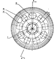
Fig. 1 is the utility model sectional drawing;
Fig. 2 is two groups of damping spring distribution maps;
Fig. 3 is the floor map of outer cover;
Fig. 4 is the A-A sectional view of Fig. 3;
Fig. 5 is the floor map of driven gear;
Fig. 6 is the B-B sectional view of Fig. 5;
Fig. 7 is the sectional structure chart after the assemblings such as outer cover, driven gear;
Fig. 8 is the floor map of central sleeve;
Fig. 9 is the C-C sectional drawing of Fig. 8;
Figure 10 is the floor map of platen;
Figure 11 is the D-D sectional drawing of Figure 10.
Among the figure:
Second group of damping spring of 1---first group of damping spring 2---
3---driven gear 4---outer cover
5---outer cover unthreaded hole 6---belleville spring groove
7---driven gear splined hole 8---outer covers and driven gear riveted joint back driven gear end are jumped
9---outer cover and driven gear riveted joint back driven gear radial composite error
10---central sleeve 11---central sleeve tooth top external diameter
12---platen 13---platen internal diameter
14---belleville spring 15---plain washer
16---cover plate 17---rivet
18---friction plate 19---steel disc
20---spring 21---lift slab
The big damping spring groove of 22---bolts 23---
24---little damping spring groove 25---outer cover rivet hole
Big damping spring hole, 26---little damping spring holes 27---
28---the driven gear rivet hole
Embodiment
Referring to Fig. 1, this clutch comprises driven gear 3, outer cover 4, central sleeve 10, first group of damping spring 1, second group of damping spring 2, platen 12, butterfly spring 14, plain washer 15, cover plate 16, friction plate 18, steel disc 19, spring 20, lift slab 21, rivet 17 and bolt 22.
Referring to Fig. 3, Fig. 4, Fig. 5, Fig. 6 and Fig. 7, be distributed with two groups of damping spring holes on the circumferential surface of driven gear 3, three every group, little damping spring hole 26 is less than big damping spring hole 27, and the cross arrangement of big or small damping spring span.And the corresponding position on the circumferential surface of outer cover 4 is distributed with two groups of damping spring grooves, and every group also is three, big damping spring groove 23 greater than with little damping spring groove 24, also be cross arrangement at interval.Two groups of damping springs of corresponding installation in these two groups of damping spring holes and groove, the steel wire diameter of first group of damping spring 1, free length, stiffness, compressive force value are all less than second group of damping spring 2, after the installation, the both ends of the surface of the both ends of the surface in the both ends of the surface of first group of damping spring 1 and the little damping spring hole 26 of outer cover 4 and the little damping spring groove 23 of driven gear 3 all contact; And the big damping spring hole 27 of driven gear 3 that second group of damping spring 2 be installed is greater than big damping spring groove 24 corresponding on the outer cover 4, after the installation, second group of damping spring 2 both ends of the surface only contact with big damping spring groove 24 both ends of the surface of outer cover 4, do not contact with the both ends of the surface in big damping spring hole 27 on the driven gear 3.The both ends of the surface that damping spring hole 27 on the driven gear 3 contacts with damping spring can be designed to the tapered in form that narrows towards driven gear 3 centers.And the rivet hole on the driven gear 3 is a slotted hole 28, and greater than rivet hole 25 corresponding on the outer cover 4, the rivet hole of rivet hole 25 for protruding on the outer cover 4 injects in the slotted hole 28 corresponding on the driven gear 3.Said structure makes that the problem that the cushion collar premature ageing lost efficacy is solved.
In addition, the center hole of outer cover 4 is a unthreaded hole 5, and the center hole of driven gear 3 then is an inner splined hole 7, and design has butterfly spring groove 6 on the mating face of outer cover 4 and driven gear 3, and butterfly spring 14 is installed in it.Inner splined hole 7 is not easy to wear on the driven gear 3 like this, long service life, and after driven gear and the outer cover riveted joint, its detection reference and design basis reach unified, so assurances that are easy to get such as the end face run-out 8 of driven gear and outer cover combination back driven gear and radial composite error 9, improve product percent of pass, reduce the noise of clutch.
Combination is referring to Fig. 8 and Fig. 9 again, and the tooth top external diameter 11 of central sleeve 10 is φ 81, and referring to Figure 10 and Figure 11, the internal diameter 13 of platen 12 is φ 82, has increased the contact friction area thus, increases positive pressure, thereby increases transmitting torque.
Again referring to Fig. 1 and Fig. 2, the assembly relation of this clutch is: in the belleville spring groove 6 of the outer cover 4 of earlier plain washer 15 being packed into, belleville spring 14 is contained on the plain washer 15, then driven gear 3 is contained on the belleville spring 14, first group of damping spring 1 and second group of damping spring 2 are contained in respectively in the damping spring hole and damping spring groove of driven gear 3 and outer cover 4, cover plate 16 is contained on the driven gear 3, rivet 17 is contained in the rivet hole of cover plate 16 and outer cover 4, riveted joint firmly.Then central sleeve 10 is contained in the outer cover 4, friction plate 18 is contained on the central sleeve 10, steel plate 19 is contained on the friction plate 18, platen 12 is contained in the screw hole of central sleeve 10,5 springs 20 are contained on the spring seat of central sleeve 10 and platen 12 formation, lift slab 21 is contained on the post of platen 12, bolt 22 is contained in the screw hole of lift slab 21 and platen 12.
The working procedure of this clutch: motor is given driven gear 3 with transmission of power, pass to outer cover 4 again by first group of damping spring 1 or second group of damping spring 2, outer cover 4 is by contacting with friction plate 18, give steel disk 19 with transmission of power, under spring 20 elastic force effects, compress steel plate 19, friction plate 18, platen 12, central sleeve 10, thereby give central sleeve 10 with transmission of power, central sleeve 10 is connected with engine spindle, thereby the transmission of power of motor is arrived motor cycle rear wheel.
Claims (6)
1. manual series motorcycle clutch, described clutch comprises driven gear (3), outer cover (4), central sleeve (10), platen (12), butterfly spring (14), plain washer (15), cover plate (16), friction plate (18), steel disc (19), spring (20), lift slab (21), rivet (17) and bolt (22);
It is characterized in that: be distributed with two groups on the circumferential surface of described driven gear (3) and vary in size and interval cross arrangement damping spring hole, be respectively little damping spring hole (26) and big damping spring hole (27), and the corresponding position on the circumferential surface of outer cover (4) is distributed with two groups and varies in size and cross arrangement damping spring groove at interval, is respectively little damping spring groove (24) and damping spring groove (23) greatly;
In driven gear (3) and last corresponding damping spring hole of outer cover (4) and groove, damping spring is installed respectively, the steel wire diameter of described first group of damping spring (1), free length, compressive force value are all less than second group of damping spring (2), first group of damping spring (1) is installed in little damping spring hole (26) and the little damping spring groove (24), and second group of damping spring (2) is installed in big damping spring hole (27) and the big damping spring groove (23);
The both ends of the surface of the both ends of the surface in the both ends of the surface of first group of damping spring (1) and the little damping spring hole (26) of outer cover (4) and the little damping spring groove (14) of driven gear (3) contact;
The big damping spring hole (27) of the driven gear (3) of second group of damping spring (2) is installed goes up corresponding big damping spring groove (23) greater than outer cover (4), second group of damping spring (2) both ends of the surface only contact with big damping spring groove (23) both ends of the surface of outer cover (4), do not contact with the both ends of the surface in the big damping spring hole (27) of driven gear (3);
Described outer cover (4) and driven gear (3) are connected as one by rivet by the cover plate (16) that is pressed in driven gear (3) outer surface; Rivet hole on the described driven gear (3) is slotted hole (28), goes up corresponding rivet hole (25) greater than outer cover (4).
2. manual series motorcycle clutch according to claim 1 is characterized in that, the rivet hole of the rivet hole (25) on the described outer cover (4) for protruding injects driven gear (3) and go up in the corresponding slotted hole (28).
3. manual series motorcycle clutch according to claim 1 is characterized in that, the center hole of described outer cover (4) is unthreaded hole (5), and the center hole of driven gear (3) then is an inner splined hole (7); Design has butterfly spring groove (6) on the mating face of described outer cover (4) and driven gear (3), and butterfly spring (14) is installed in it.
4. manual series motorcycle clutch according to claim 1 is characterized in that, the both ends of the surface that the big damping spring hole (27) on the described driven gear (3) contacts with damping spring are designed to the tapered in form that narrows towards driven gear (3) center.
5. manual series motorcycle clutch according to claim 1 is characterized in that, the tooth top external diameter (11) of described central sleeve (10) is φ 80~φ 83, and the internal diameter (13) of platen (12) is φ 81~φ 85.
6. manual series motorcycle clutch according to claim 1 is characterized in that, described spring (20) quantity is 5.
Priority Applications (1)
| Application Number | Priority Date | Filing Date | Title |
|---|---|---|---|
| CN200920294290XU CN201621200U (en) | 2009-12-31 | 2009-12-31 | Manual series motorcycle clutch |
Applications Claiming Priority (1)
| Application Number | Priority Date | Filing Date | Title |
|---|---|---|---|
| CN200920294290XU CN201621200U (en) | 2009-12-31 | 2009-12-31 | Manual series motorcycle clutch |
Publications (1)
| Publication Number | Publication Date |
|---|---|
| CN201621200U true CN201621200U (en) | 2010-11-03 |
Family
ID=43024655
Family Applications (1)
| Application Number | Title | Priority Date | Filing Date |
|---|---|---|---|
| CN200920294290XU Expired - Fee Related CN201621200U (en) | 2009-12-31 | 2009-12-31 | Manual series motorcycle clutch |
Country Status (1)
| Country | Link |
|---|---|
| CN (1) | CN201621200U (en) |
Cited By (3)
| Publication number | Priority date | Publication date | Assignee | Title |
|---|---|---|---|---|
| CN102889316A (en) * | 2012-10-23 | 2013-01-23 | 重庆赛特尔机械有限公司 | Friction plate component of automobile clutch |
| CN103814229A (en) * | 2011-11-17 | 2014-05-21 | 株式会社F.C.C. | Clutch device |
| CN111692226A (en) * | 2019-03-13 | 2020-09-22 | Tvs电机股份有限公司 | Internal combustion engine for a motor vehicle |
-
2009
- 2009-12-31 CN CN200920294290XU patent/CN201621200U/en not_active Expired - Fee Related
Cited By (5)
| Publication number | Priority date | Publication date | Assignee | Title |
|---|---|---|---|---|
| CN103814229A (en) * | 2011-11-17 | 2014-05-21 | 株式会社F.C.C. | Clutch device |
| CN103814229B (en) * | 2011-11-17 | 2016-08-31 | 株式会社F.C.C. | Clutch apparatus |
| CN102889316A (en) * | 2012-10-23 | 2013-01-23 | 重庆赛特尔机械有限公司 | Friction plate component of automobile clutch |
| CN111692226A (en) * | 2019-03-13 | 2020-09-22 | Tvs电机股份有限公司 | Internal combustion engine for a motor vehicle |
| CN111692226B (en) * | 2019-03-13 | 2022-03-22 | Tvs电机股份有限公司 | Internal combustion engine for a motor vehicle |
Similar Documents
| Publication | Publication Date | Title |
|---|---|---|
| CN201621200U (en) | Manual series motorcycle clutch | |
| CN103307124B (en) | High speed rotor location connecting structure | |
| CN201615149U (en) | Clutch housing assembly of manual clutch motorbike | |
| CN202628727U (en) | Split crankshaft gear of high-power diesel engine | |
| CN211778656U (en) | Hydraulic brake | |
| CN111288089A (en) | Wind power coupling | |
| CN210510228U (en) | Torsion arm and pin shaft connecting structure of wind power gear box and wind power gear box | |
| CN201723440U (en) | Gear pump | |
| CN204784288U (en) | Realize wet clutch structure of concentricity output | |
| CN201196223Y (en) | Pneumatic friction clutch | |
| CN201615147U (en) | Clutch driven gear of manual clutch motorbike | |
| CN216589763U (en) | Torsional vibration damping system of transmission system | |
| CN202690958U (en) | Duplex rack wheel group for coal mining machine | |
| CN201615148U (en) | Clutch housing of manual clutch motorbike | |
| CN201687915U (en) | Balance gear for motorcycle engine | |
| CN200968381Y (en) | Manual wet clutch | |
| CN208294979U (en) | Wear-resistant temperature-resistant formula tractor clutch clutch drived disk assy | |
| CN206889525U (en) | A kind of gearbox wet clutch | |
| CN101959706B (en) | Drive for a hybrid vehicle and clutch with release mechanism | |
| CN200978897Y (en) | Hand-operated wet clutch | |
| CN205715485U (en) | A kind of 2AT variator of lock ring and application thereof | |
| CN108180231A (en) | Wear-resistant temperature-resistant formula clutch driven disc assembly | |
| CN212616028U (en) | Brake clearance automatic adjustment arm device | |
| CN220748878U (en) | Air pressure disc brake clearance self-adjusting device | |
| CN215409850U (en) | Friction ring |
Legal Events
| Date | Code | Title | Description |
|---|---|---|---|
| C14 | Grant of patent or utility model | ||
| GR01 | Patent grant | ||
| CF01 | Termination of patent right due to non-payment of annual fee |
Granted publication date: 20101103 Termination date: 20141231 |
|
| EXPY | Termination of patent right or utility model |