CN201598809U - Anchoring batten - Google Patents
Anchoring batten Download PDFInfo
- Publication number
- CN201598809U CN201598809U CN2010201331687U CN201020133168U CN201598809U CN 201598809 U CN201598809 U CN 201598809U CN 2010201331687 U CN2010201331687 U CN 2010201331687U CN 201020133168 U CN201020133168 U CN 201020133168U CN 201598809 U CN201598809 U CN 201598809U
- Authority
- CN
- China
- Prior art keywords
- base
- gland
- anchoring batten
- anchoring
- location division
- Prior art date
- Legal status (The legal status is an assumption and is not a legal conclusion. Google has not performed a legal analysis and makes no representation as to the accuracy of the status listed.)
- Expired - Fee Related
Links
Images
Landscapes
- Building Environments (AREA)
Abstract
The utility model discloses an anchoring batten, which belongs to building materials, and structurally comprises a gland and a base, wherein the gland consists of a lapping portion and a positioning portion. The positioning portion is disposed on the lower portion of the lapping portion, the gland is a strip which is provided with T-shaped section and extends along the length, the base is a strip groove engaged with the gland, the base is fixed with a wall via a tightening device, and anti-release structures engaged mutually are arranged at an engagement position of the positioning portion of the gland and the base. Compared with the prior art, battens and plates can be adhered tightly, and the anchoring batten has the advantages of avoiding forming clearances among the battens and the plates, avoiding water and wind entry, improving protective performance and decorative effect, achieving convenient installation, obviously improving and enhancing comfortableness in using state and the like, and then has fine popularization and application values.
Description
Technical field
The utility model relates to a kind of constructional materials, especially a kind of anchoring batten.
Background technology
Now in carrying out the sheet material installation process, the capital is to expand with heat and contract with cold to leave enough extendable room seams, but present employed mode is to use the fixed press strip of one, during use, earlier press strip and body of wall are fixed, and then sheet material is inserted in the press strip, this mode need be reserved the surplus slit is installed, after sheet material inserts in the press strip, also can have the slit, and this slit can cause wind or water to enter between sheet material and the body of wall, the water that enters penetrates between sheet material and the body of wall, cause sheet material to drop from body of wall, cause damage, and inconvenience is installed, can not fit tightly between press strip and the sheet material, leave the slit, influence attractive in appearance.At present, good solution is not also arranged.
The utility model content
Technical assignment of the present utility model is to provide a kind of anchoring batten at above-mentioned deficiency of the prior art; this anchoring batten has between press strip and the sheet material and can fit tightly; avoided there is the slit between press strip and the sheet material; avoid into water air intake; its protective value and decorative effect have been improved, characteristics easy for installation.
The technical scheme that its technical problem that solves the utility model adopts is: it comprises gland and base, described gland comprises clinch and location division, described location division is arranged on the bottom of clinch, described gland is the bar shape that has T section and extend along length, the bar grooved of described base for matching with gland, described base is fixed by fastener and body of wall, and the location division of described gland and base cooperation place are provided with the disconnecting prevention structure that can cooperatively interact.
Described disconnecting prevention structure is the fluking type disconnecting prevention structure that hangs tag.
Described fastener is a fastening bolt, and base is provided with a plurality of bolts hole, and base passes bolt hole by fastening bolt and body of wall fixes.
The top side turnover edge part of described clinch is a curved portions.
Anchoring batten of the present utility model is compared with prior art; has following outstanding beneficial effect: can fit tightly between press strip and the sheet material; avoided there is the slit between press strip and the sheet material; avoid into water air intake; its protective value and decorative effect have been improved; easy for installation, and can significantly improve its characteristics such as comfortableness when user mode.
Description of drawings
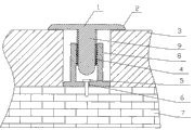
Accompanying drawing 1 is the structural representation of anchoring batten;
Description of reference numerals: 1, clinch, 2, curved portions, 3, sheet material, 4, disconnecting prevention structure, 5, fastener, 6, bolt hole, 7, body of wall, 8, base, 9, the location division.
The specific embodiment
With reference to explaining below 1 pair of anchoring batten work of the present utility model of Figure of description.
Anchoring batten of the present utility model, its structure comprises gland and base 8, described gland comprises clinch 1 and location division 9, described location division 9 is arranged on the bottom of clinch 1, described gland is the bar shape that has T section and extend along length, the bar grooved of described base 8 for matching with gland, described base 8 is fixing with body of wall 7 by fastener 5, and the location division 9 and base 8 cooperation places of described gland are provided with the disconnecting prevention structure 4 that can cooperatively interact.
Described disconnecting prevention structure 4 is the fluking type disconnecting prevention structure that hangs tag.
Described fastener 5 is a fastening bolt, and base 8 is provided with a plurality of bolts hole 6, and base 8 passes bolt hole 6 by fastening bolt and fixes with body of wall 7.
The top side turnover edge part of described clinch 1 is a curved portions 2.Improve its protective value and decorative effect, and can significantly improve its comfortableness when user mode.
Be fixed in base 8 on the body of wall 7 of sheet material 3 seam portions by fastener 5 during use, again the location division on the gland 9 is pressed into base 8, this moment matches with disconnecting prevention structure 4 on the base 8 in location division 9, closely matched with base 8 in location division 9 on the gland, clinch 1 on the gland and the sheet material 3 of seam cooperate and cover the seam of 3 of sheet materials, have avoided the seam crossing water inlet.
Except that the described technical characterictic of manual, be the known technology of those skilled in the art.
Claims (4)
1. anchoring batten, it is characterized in that: comprise gland and base, described gland comprises clinch and location division, described location division is arranged on the bottom of clinch, described gland is the bar shape that has T section and extend along length, the bar grooved of described base for matching with gland, described base is fixed by fastener and body of wall, and the location division of described gland and base cooperation place are provided with the disconnecting prevention structure that can cooperatively interact.
2. according to the said anchoring batten of claim 1, it is characterized in that: described disconnecting prevention structure is the fluking type disconnecting prevention structure that hangs tag.
3. anchoring batten according to claim 1 is characterized in that: described fastener is a fastening bolt, and base is provided with a plurality of bolts hole, and base passes bolt hole by fastening bolt and body of wall fixes.
4. anchoring batten according to claim 1 is characterized in that: the top side turnover edge part of described clinch is a curved portions.
Priority Applications (1)
| Application Number | Priority Date | Filing Date | Title |
|---|---|---|---|
| CN2010201331687U CN201598809U (en) | 2010-03-17 | 2010-03-17 | Anchoring batten |
Applications Claiming Priority (1)
| Application Number | Priority Date | Filing Date | Title |
|---|---|---|---|
| CN2010201331687U CN201598809U (en) | 2010-03-17 | 2010-03-17 | Anchoring batten |
Publications (1)
| Publication Number | Publication Date |
|---|---|
| CN201598809U true CN201598809U (en) | 2010-10-06 |
Family
ID=42809862
Family Applications (1)
| Application Number | Title | Priority Date | Filing Date |
|---|---|---|---|
| CN2010201331687U Expired - Fee Related CN201598809U (en) | 2010-03-17 | 2010-03-17 | Anchoring batten |
Country Status (1)
| Country | Link |
|---|---|
| CN (1) | CN201598809U (en) |
Cited By (2)
| Publication number | Priority date | Publication date | Assignee | Title |
|---|---|---|---|---|
| CN101806140A (en) * | 2010-03-17 | 2010-08-18 | 山东德宝建筑节能技术有限公司 | Anchoring batten |
| CN104499627A (en) * | 2014-12-18 | 2015-04-08 | 无锡王兴幕墙装饰工程有限公司 | Ceiling expansion joint with aluminum plates |
-
2010
- 2010-03-17 CN CN2010201331687U patent/CN201598809U/en not_active Expired - Fee Related
Cited By (2)
| Publication number | Priority date | Publication date | Assignee | Title |
|---|---|---|---|---|
| CN101806140A (en) * | 2010-03-17 | 2010-08-18 | 山东德宝建筑节能技术有限公司 | Anchoring batten |
| CN104499627A (en) * | 2014-12-18 | 2015-04-08 | 无锡王兴幕墙装饰工程有限公司 | Ceiling expansion joint with aluminum plates |
Similar Documents
| Publication | Publication Date | Title |
|---|---|---|
| CN103469971B (en) | A kind of metal Roof system | |
| CN202467009U (en) | External hanging catching groove structure of plug-in type upright side hidden-interlocking roof panel | |
| CN101806140A (en) | Anchoring batten | |
| CN201598809U (en) | Anchoring batten | |
| CN205348493U (en) | Aluminum covered steel curtain wall section material structure | |
| CN206016135U (en) | A kind of concealed metope outside plate | |
| CN201268905Y (en) | Roofing ceiling underplate | |
| CN208899760U (en) | A kind of connection system of metal Roof decorative panel | |
| CN204290834U (en) | Photovoltaic watt | |
| CN202577782U (en) | Aluminum alloy buckling strip and fittings thereof, sun sheet fittings and connection structure | |
| CN201043429Y (en) | Clamping groove for sealing strip on door of baking finish house | |
| CN202787851U (en) | Horizontal hanging element for clay plate | |
| CN201665937U (en) | Roof-wall panel and fixed support combined barb-shaped pull-out resistant locking structure | |
| CN219411566U (en) | Lower-mounted photovoltaic car shed system | |
| CN206769090U (en) | A kind of wall body structure of Double-layer profiled steel sheet complex heat-preservation | |
| CN202534668U (en) | Fixing support for mounting solar cell panel without damaging roof sheathing | |
| CN205777142U (en) | The roof board system of wind uplift resistance can be improved | |
| CN213927116U (en) | Special-shaped double-layer waterproof metal roof structure | |
| CN209723419U (en) | A kind of flashing plate system and side gable, ridge, cornice, parapet with metal support | |
| CN108842969A (en) | A kind of the connection system and its operating method of metal Roof decorative panel | |
| CN204781631U (en) | Special steel bottom plate of individual layer prepared roofing | |
| CN217461143U (en) | Easily install assembled suspended ceiling structure of tearing open | |
| CN203412209U (en) | Rain-tight lighting tile | |
| CN220539033U (en) | Various steel tile structure convenient to photovoltaic board installation | |
| CN203867084U (en) | Pitched roof photovoltaic color steel tile installing and fixing device |
Legal Events
| Date | Code | Title | Description |
|---|---|---|---|
| C14 | Grant of patent or utility model | ||
| GR01 | Patent grant | ||
| CF01 | Termination of patent right due to non-payment of annual fee | ||
| CF01 | Termination of patent right due to non-payment of annual fee |
Granted publication date: 20101006 Termination date: 20180317 |