CN201439039U - Water filtration device - Google Patents
Water filtration device Download PDFInfo
- Publication number
- CN201439039U CN201439039U CN2009201633862U CN200920163386U CN201439039U CN 201439039 U CN201439039 U CN 201439039U CN 2009201633862 U CN2009201633862 U CN 2009201633862U CN 200920163386 U CN200920163386 U CN 200920163386U CN 201439039 U CN201439039 U CN 201439039U
- Authority
- CN
- China
- Prior art keywords
- filtering
- plate
- dividing plate
- chamber
- filtering chamber
- Prior art date
- Legal status (The legal status is an assumption and is not a legal conclusion. Google has not performed a legal analysis and makes no representation as to the accuracy of the status listed.)
- Expired - Fee Related
Links
Images


Abstract
The utility model discloses a water filtration device, which comprises a shell and a partition board device arranged in the shell; the partition board device divides the interior of the shell into a plurality of pre-filter chambers and a main filter chamber; individual pre-filter chambers are filled with filter material and is communicated with a water inlet on the shell; the main filter chamber is communicated with a water outlet on the shell, and the main filter chamber is provided with at least a filter element; and when raw water is led into the shell through the water inlet, the raw water is first filtered by the filter material in the pre-filter chambers, and then overflows to the main filter chamber and is filtered into pure water by the filter element, and the filtered pure water can flow out through the water outlet for use.
Description
Technical field
The utility model provides a kind of water treatment plant, is meant especially a kind ofly by filter material former water to be filtered so that the water treatment plant of water purification to be provided.
Background technology
The escalator machine room top in roof, staircase or the building of general family disposes mostly and can store running water or phreatic water tower or pond the people has a bath, washed, the usefulness of washing dish and diet to provide.Advanced the unclean of water easily and influenced but store water quality in water tower or pond, especially, along with progress of industry, chemical plant, manufacturing industry factory (as steel plant, factory etc. dyes cloth) stand in great numbers, cause sewage emissions amount day more to promote, make also to be subjected to severe contamination by still very clean in the past underground water.
For ensureing the security of people's water, the multiple purifier that provides the water tower water storage to use is provided in the utility model designer design, uses former water is filtered earlier to remove filth, is transported in water tower or the pond again and stores.These purifiers have good effect in the use.
Up to the present, be the clean-up effect of increasing water quality, the utility model designer has generation of the present utility model after design improved.
Summary of the invention
Edge this, main purpose of the present utility model is providing a kind of water treatment plant, the filter chamber that this water treatment plant has a multiple tracks is in order to forming clean water with the contaminant filter in the former water, and this water treatment plant has simple structure.
The water treatment plant that constitutes according to a preferred embodiment of the present utility model comprises a housing, a baffle plate device and a filter element device; This housing has a top board, a base plate and the side plate between this top board and base plate, has a water inlet and a delivery port on this housing; This baffle plate device comprises plural dividing plate, and this is counted dividing plate this enclosure interior is separated into a plural pre-filtering chamber and a main filter chamber, and this is counted, and pre-filtering is indoor to be filled with filter material individually and to be communicated with the water inlet of this housing, and this main filter chamber is communicated with this delivery port; This filter element device is installed in the main filter chamber of this housing and comprises at least one filter core; After former water is introduced in this housing via this water inlet, can flow through in regular turn that this is counted the pre-filtering chamber and counts the indoor filter material of pre-filtering for this and filter earlier, overflow is to this main filter chamber and be that the filter element filtering of this filter element device becomes water purification again.
In the preferred embodiment, the side plate of this housing comprises header board, back plate, left plate and right plate, and this baffle plate device comprises first dividing plate, second partition and the 3rd dividing plate; First dividing plate is located at this room top obliquely and has the upper end that is combined in the left plate top inner wall and be combined in the lower end of right plate inwall; This second partition is located in this room obliquely and is positioned at the below of this first dividing plate, and this second partition has the lower end that is combined in this left plate inwall and is combined in the upper end of the lower end of contiguous this first dividing plate; The 3rd dividing plate is positioned at the below of this second partition and generally is cylindric, defines this main filter chamber in the 3rd dividing plate, and this main filter chamber provides this filter element device to take in.
In the preferred embodiment, form one first pre-filtering chamber between this first dividing plate, this housing top board and this housing side plate, this first pre-filtering chamber is communicated with this water inlet; Form second a pre-filtering chamber that is communicated with this first pre-filtering chamber between this first dividing plate, this second partition and this housing side plate; Form one the 3rd pre-filtering chamber between the 3rd dividing plate, this second partition and this housing right plate; Form one the 4th pre-filtering chamber between the 3rd dividing plate, this second partition and this housing left plate; In each pre-filtering chamber, individually put into filter material.This top board is provided with a filter material feed pipe, and the upper end of this feed pipe has plural slotted eye, makes this first pre-filtering chamber be connected with this second pre-filtering chamber; Be provided with a webmaster between the upper end of this second partition and this first dividing plate, the front end of this webmaster has an opening, makes this second pre-filtering chamber be connected with the 3rd pre-filtering chamber; The lower end of the 3rd dividing plate has plural aperture, makes the 3rd pre-filtering chamber be connected with the 4th pre-filtering chamber; The bottom surface of this second partition is provided with a conduit, and the lower end of this conduit is positioned at the 4th pre-filtering chamber and the upper end extends to this main filter chamber, makes the top of the 4th pre-filtering chamber be connected with this main filter chamber.
In the preferred embodiment, this water inlet is located on this top board, and the bottom of this water inlet extends in this room top and has the bore that dwindles and form a nozzle.This delivery port is located on this base plate, this delivery port is positioned at the bottom of a funnelform outlet pipe, the top periphery of this outlet pipe combines with the periphery of this filter core seat board, and this outlet pipe and this filter core seat board are fixed on this base plate jointly, and this filter element device is installed on this filter core seat board.。
About other purpose of the present utility model, advantage and feature, can understand by following DETAILED DESCRIPTION OF THE PREFERRED and with reference to accompanying drawing.
Description of drawings
Fig. 1 is the stereogram according to the water treatment plant of embodiment formation of the present utility model.
Fig. 2 is the assembly exploded view of the water treatment plant of demonstration Fig. 1.
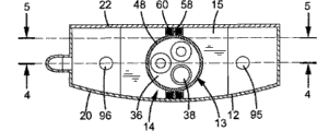
Fig. 3 is a transverse sectional view of the water treatment plant of demonstration Fig. 1.
The cutaway view that Fig. 4 is intercepted for the 4-4 line along Fig. 3.
The cutaway view that Fig. 5 is intercepted for the 5-5 line along Fig. 3.
Fig. 6 is the enforcement state reference map of the water treatment plant of demonstration Fig. 1.
[primary clustering symbol description]
10. water treatment plant 12. housings
13. filter element device 14. baffle plate devices
15. room 16. top boards
18. base plate 20. header boards
22. back plate 24. left plates
26. right plate 28. water inlets
30. bottom 31. taps
32. delivery port 34. outlet pipes
36. filter core seat board 38. filter cores
40. outlet valve 41. main filter chambers
42. first dividing plate, 44. second partitions
48. the 3rd dividing plate 50. upper ends
51. punching net 52. lower ends
54. lower end 55. webmasters
56. upper end 58. flanges
60. aperture 62. first ends
64. second end pre-filtering chambers 66. first
68. the 3rd pre-filtering chamber, the second pre-filtering chamber 70.
72. the 4th pre-filtering chamber 74. feed pipes
75. slotted eye 76. openings
80. conduit 82.84. filter material
86.88. filter material 89. charging apertures
90. sewage outlet 91. charging apertures
92. outlet 93.94. outlet
95.96. outlet 97. former water
The specific embodiment
The utility model can be implemented with multiple different form.Now will only be example but non-embodiment and as follows with regard to preferred structure description of contents of the present utility model with reference to accompanying drawing in order to restriction:
Consult Fig. 1 to Fig. 5, show the water treatment plant 10 that constitutes according to a preferred embodiment of the present utility model, this water treatment plant 10 can provide and be installed in for example kitchen or other place that needs cleandrinking water of general family.
This water treatment plant 10 comprises a housing 12, is located at a filter element device 13 and a baffle plate device 14 of these housing 12 inside; These housing 12 inside have a room 15, and this housing 12 comprises a top board 16, a base plate 18 and the side plate between this top board 16 and base plate 18, and in the present embodiment, the side plate of this housing 12 comprises header board 20, back plate 22, left plate 24 and right plate 26.Have a water inlet 28 on this top board 16, the bottom 30 of this water inlet 28 extends in these room 15 tops and has the bore that dwindles and form a nozzle, and the top of this water inlet 28 can connect a tap 31 (see figure 6)s or supply the water pipe of former water; Has a water outlet 32 on this base plate 18, in the present embodiment, this delivery port 32 is positioned at the bottom of a funnelform outlet pipe 34, the top periphery of this outlet pipe 34 combines with the periphery of a filter core seat board 36, and this outlet pipe 34 is fixed on this base plate 18 jointly with this filter core seat board 36, provides this filter element device 13 installings on this filter core seat board 36, in the present embodiment, this filter element device 13 is located at these room 15 bottoms and comprises three tubular element 38, and this delivery port 32 connects an outlet valve 40 again.
This baffle plate device 14 comprises plural dividing plate in order to this housing 1 internal capacity room 15 is separated into a plural pre-filtering chamber and a main filter chamber 41; In the present embodiment, this baffle plate device 14 comprises first dividing plate 42, second partition 44 and the 3rd dividing plate 48; First dividing plate 42 is located at these room 15 tops obliquely and has the upper end 50 that is combined in left plate 24 top inner wall and be combined in the lower end 52 of right plate 26 inwalls.Below near water inlet 28, be provided with a punching net 51 on this first dividing plate 42.
Form one first pre-filtering chamber 66 between this first dividing plate 42, this housing top board 16 and the housing side plate, this first pre-filtering chamber 66 is communicated with water inlet 28; Form second a pre-filtering chamber 68 that is communicated with this first pre-filtering chamber 66 between first dividing plate 42, second partition 44 and the housing side plate; Form one the 3rd pre-filtering chamber 70 between the 3rd dividing plate 48, second partition 44 and the housing right plate 26; Form one the 4th pre-filtering chamber 72 between the 3rd dividing plate 48, second partition 44 and the housing left plate 24; Be provided with a filter material feed pipe 74 on this top board 16, the upper end of this feed pipe 74 has plural slotted eye 75, and the pre-filtering chamber 66 of winning is connected with the second pre-filtering chamber 68; Be provided with a webmaster 55 between the upper end 56 of this second partition 44 and this first dividing plate 42, the front end of this webmaster 55 has an opening 76, makes the second pre-filtering chamber 68 be connected with the 3rd pre-filtering chamber 70; And as mentioned above, the lower end of the 3rd dividing plate 48 has plural aperture 60, make the 3rd pre-filtering chamber 70 be connected with the 4th pre-filtering chamber 72, be provided with a conduit 80 again in the bottom surface of this second partition 44, the lower end of this conduit 80 is positioned at the 4th pre-filtering chamber 72 and the upper end extends to main filter chamber 41, makes the top of the 4th pre-filtering chamber 72 be connected with main filter chamber 41.
In each pre-filtering chamber 66,68,70,72, individually put into filter material 82,84,86,88.In the present embodiment, fill violent sand filter material pre-filtering chambers 82, the second 68 interior fillings in this first pre-filtering chamber 66 and fill filling medical stone filter material 88 in the exchanger resin filter material pre-filtering chambers 72 86, the four in the active carbon filtration material pre-filtering chambers 70 84, the three.In the present embodiment, this top board 16 is provided with a violent sand charging aperture 89 and fills in violent sand to the first pre-filtering chamber 66 in order to provide, and extend in the second pre-filtering chamber 68 in order to provide in filling activated carbon to the second pre-filtering chamber 68 bottom of above-mentioned filter material feed pipe 74; Right plate 26 is provided with a sewage outlet 90, a resin feeding mouth 91, one violent sand outlet 92, and this sewage outlet 90 is communicated with the first pre-filtering chamber 66 in order to discharge the sewage in the first pre-filtering chamber 66.Punching net 51 on first dividing plate 42 can prevent that violent sand filter material 82 from falling into sewage outlet 90; Left plate 24 is provided with an activated carbon outlet 93 and a medical stone charging aperture 94; Base plate 18 is provided with a resin outlet 95 and a medical stone outlet 96.Violent sand outlet 92, activated carbon outlet 93, resin outlet 95 and medical stone outlet 96 are in sealing at ordinary times, when this water treatment plant 10 uses a period of times and will clean or when changing filter material, can open violent sand outlet 92, activated carbon outlet 93, resin outlet 95 and medical stone outlet 96.
According to the formed water treatment plant 10 of the utility model in the enforcement of drainage, former water 97 (as the arrow indication of Fig. 4) is introduced in the first pre-filtering chamber 66 via water inlet 28, and done preliminary filtration by violent sand filter material 82, then, filter via in the feed pipe 74 inflows second pre-filtering chamber 68 of guiding water function, being done second road by active carbon filtration material 84, flow in the 3rd pre-filtering chamber 70 via webmaster 55 again and done the filtration of the 3rd road by resin filter material 86, after filter by being done the 4th road by medical stone filter material 88 in the 3rd dividing plate 48 inflows the 4th pre-filtering chamber 72, then, flow into main filter chamber 41 interior further filtrations by filter core 38 via conduit 80 and form clean waters, this water purification can flow out by this outlet pipe 34 and supply to take.
According to the formed water treatment plant 10 of the utility model in the process of carrying out water filtration, consult shown in Figure 4, former water 97 flows from pre-filtering chambers 72 66 to the 4th, the first pre-filtering chamber, mostly be just can overflow after former water 97 completely arrives certain altitude to next pre-filtering chamber, so the impurity that is filtered in each pre-filtering chamber will be deposited in the bottom of each pre-filtering chamber and can not flow along with former water 97; Especially, the water of the 4th pre-filtering chamber 72 will completely arrive after the certain altitude just can be via conduit 80 overflows to main filter chamber 41, thereby the impurity that is filtered by the 4th pre-filtering chamber 72 will can not flow in the main filter chamber 41.So water treatment plant 10 of the present utility model can effectively filter former water, and the need of clean water to provide people to live are provided.
Aforementioned is the explanation of structure of the present utility model being made preferred embodiment, is can do multiple variation or modify embodiment and comply with design spirit of the present utility model.So,, will be incorporated within the claim that the utility model advocates for obvious replacement and the modification that the personage who is familiar with this technology can do.
Claims (8)
1. a water treatment plant is characterized in that, comprises:
One housing, its inside has a room, and this housing includes a top board, a base plate and the side plate between this top board and base plate, has a water inlet and a delivery port on this housing;
One baffle plate device, it comprises plural dividing plate, this is counted dividing plate the internal capacity room of this housing is separated into a plural pre-filtering chamber and a main filter chamber, and this is counted, and pre-filtering is indoor to be filled with filter material individually and to be communicated with the water inlet of this housing, and this main filter chamber is communicated with this delivery port; And
One filter element device, it is installed in the main filter chamber of this housing and comprises at least one filter core;
After former water is introduced in this housing via this water inlet, can flowing through in regular turn, this is counted the pre-filtering chamber and is that this is counted the indoor filter material of pre-filtering and filters earlier, overflow is to this main filter chamber and be that the filter element filtering of this filter element device becomes water purification again, and the water purification after the filtration can flow out by this delivery port and supply to take.
2. water treatment plant as claimed in claim 1 is characterized in that, the side plate of this housing comprises header board, back plate, left plate and right plate, and this baffle plate device comprises first dividing plate, second partition and the 3rd dividing plate; This first dividing plate is located at this room top obliquely and has the upper end that is combined in this left plate top inner wall and be combined in the lower end of this right plate inwall; This second partition is located in this room obliquely and is positioned at the below of this first dividing plate, and this second partition has the lower end that is combined in this left plate inwall and is combined in the upper end of the lower end of contiguous this first dividing plate; The 3rd dividing plate is positioned at the below of this second partition and generally is cylindric, defines this main filter chamber in the 3rd dividing plate, and take in for this filter element device this main filter chamber.
3. water treatment plant as claimed in claim 2 is characterized in that, forms one first pre-filtering chamber between this first dividing plate, this housing top board and this housing side plate, and this first pre-filtering chamber is communicated with this water inlet; Form second a pre-filtering chamber that is communicated with this first pre-filtering chamber between this first dividing plate, this second partition and this housing side plate; Form one the 3rd pre-filtering chamber between the 3rd dividing plate, this second partition and this housing right plate; Form one the 4th pre-filtering chamber between the 3rd dividing plate, this second partition and this housing left plate; In each pre-filtering chamber, individually put into filter material.
4. water treatment plant as claimed in claim 3 is characterized in that, this top board is provided with a filter material feed pipe, and the upper end of this feed pipe has plural slotted eye, makes this first pre-filtering chamber be connected with this second pre-filtering chamber; Be provided with a webmaster between the upper end of this second partition and this first dividing plate, the front end of this webmaster has an opening, makes this second pre-filtering chamber be connected with the 3rd pre-filtering chamber; The lower end of the 3rd dividing plate has plural aperture, makes the 3rd pre-filtering chamber be connected with the 4th pre-filtering chamber; The bottom surface of this second partition is provided with a conduit, and the lower end of this conduit is positioned at the 4th pre-filtering chamber and the upper end extends to this main filter chamber, makes the top of the 4th pre-filtering chamber be connected with this main filter chamber.
5. water treatment plant as claimed in claim 4, it is characterized in that, the 3rd dividing plate has first end and second end that is combined on this base plate of the bottom surface that is combined in this second partition, the 3rd dividing plate around and be extended with the flange that is combined in individually on this header board and this back plate, this of the 3rd dividing plate counted the bottom that the aperture is located at each flange.
6. water treatment plant as claimed in claim 5, it is characterized in that the violent sand filter material of the indoor filling of this first pre-filtering, the indoor filling activated carbon filtration of this second pre-filtering material, the indoor filling exchanger resin of the 3rd pre-filtering filter material, the indoor filling medical stone of the 4th pre-filtering filter material; This top board is provided with a violent sand charging aperture in order to provide the violent sand of filling indoor to this first pre-filtering; It is indoor to provide the filling active carbon indoor to this second pre-filtering that this second pre-filtering is extended in the bottom of this filter material feed pipe; This right plate is provided with a sewage outlet, a resin feeding mouth and a violent sand outlet, this sewage outlet is communicated with this first pre-filtering chamber in order to discharging the indoor sewage of this first pre-filtering, and is provided with a punching net below near this water inlet on this first dividing plate and falls into sewage outlet in order to prevent this violent sand filter material.
7. water treatment plant as claimed in claim 3 is characterized in that, this water inlet is located on this top board, and the bottom of this water inlet extends in this room top and has the bore that dwindles and form a nozzle.
8. water treatment plant as claimed in claim 7, it is characterized in that, this delivery port is located on this base plate, this delivery port is positioned at the bottom of a funnelform outlet pipe, the top periphery of this outlet pipe combines with the periphery of this filter core seat board, this outlet pipe and this filter core seat board are fixed on this base plate jointly, and this filter element device is installed on this filter core seat board.
Priority Applications (1)
| Application Number | Priority Date | Filing Date | Title |
|---|---|---|---|
| CN2009201633862U CN201439039U (en) | 2009-07-08 | 2009-07-08 | Water filtration device |
Applications Claiming Priority (1)
| Application Number | Priority Date | Filing Date | Title |
|---|---|---|---|
| CN2009201633862U CN201439039U (en) | 2009-07-08 | 2009-07-08 | Water filtration device |
Publications (1)
| Publication Number | Publication Date |
|---|---|
| CN201439039U true CN201439039U (en) | 2010-04-21 |
Family
ID=42543711
Family Applications (1)
| Application Number | Title | Priority Date | Filing Date |
|---|---|---|---|
| CN2009201633862U Expired - Fee Related CN201439039U (en) | 2009-07-08 | 2009-07-08 | Water filtration device |
Country Status (1)
| Country | Link |
|---|---|
| CN (1) | CN201439039U (en) |
Cited By (4)
| Publication number | Priority date | Publication date | Assignee | Title |
|---|---|---|---|---|
| CN103084002A (en) * | 2013-02-06 | 2013-05-08 | 沛毅工业股份有限公司 | Filter with combined type filter material |
| CN103816713A (en) * | 2014-02-26 | 2014-05-28 | 明圣化工机械(南通)有限公司 | Sewage processor |
| CN104230006A (en) * | 2014-08-21 | 2014-12-24 | 浙江荣晟环保纸业股份有限公司 | Sewage calcium removal device for papermaking industry |
| CN111335850A (en) * | 2020-04-15 | 2020-06-26 | 郑春辉 | Sand control screen pipe capable of adjusting aperture of screen hole |
-
2009
- 2009-07-08 CN CN2009201633862U patent/CN201439039U/en not_active Expired - Fee Related
Cited By (6)
| Publication number | Priority date | Publication date | Assignee | Title |
|---|---|---|---|---|
| CN103084002A (en) * | 2013-02-06 | 2013-05-08 | 沛毅工业股份有限公司 | Filter with combined type filter material |
| CN103084002B (en) * | 2013-02-06 | 2014-11-19 | 沛毅工业股份有限公司 | Filter with combined type filter material |
| CN103816713A (en) * | 2014-02-26 | 2014-05-28 | 明圣化工机械(南通)有限公司 | Sewage processor |
| CN104230006A (en) * | 2014-08-21 | 2014-12-24 | 浙江荣晟环保纸业股份有限公司 | Sewage calcium removal device for papermaking industry |
| CN104230006B (en) * | 2014-08-21 | 2015-10-28 | 浙江荣晟环保纸业股份有限公司 | For the sewage calcium-removing device of paper-making industry |
| CN111335850A (en) * | 2020-04-15 | 2020-06-26 | 郑春辉 | Sand control screen pipe capable of adjusting aperture of screen hole |
Similar Documents
| Publication | Publication Date | Title |
|---|---|---|
| CN201439039U (en) | Water filtration device | |
| CA2656088A1 (en) | Water treatment device | |
| CN207219825U (en) | The New aquarium for improving filter effect based on water circulation system | |
| CN206473882U (en) | A kind of tandem type multi-stage filter | |
| CN209501042U (en) | A kind of filter device | |
| CN205115189U (en) | Efficient integrated sewage treatment equipment | |
| CN102258903B (en) | Filter device with inverted T-shaped filter screen for multiple filtrations | |
| CN201520687U (en) | Gravity type integrated water purifier with ring-shaped water cleaning box | |
| CN211847417U (en) | Full-automatic timing blowdown backwash water purifier without electricity | |
| CN210125227U (en) | Filter element of household water purifier | |
| CN208980533U (en) | A kind of sludge and sewage dual treatment device | |
| CN209161620U (en) | A kind of integral type too many levels pretreatment water tank | |
| CN208911578U (en) | A kind of filter device being not easy to plug | |
| JP4688049B2 (en) | Water purifier and backwash method for water purifier | |
| CN207042051U (en) | Water purifier water route integrated morphology | |
| CN211170198U (en) | Filter | |
| CN104973690B (en) | A kind of purification tank | |
| CN218146028U (en) | Aeration biological filter tank | |
| CN219815581U (en) | Novel sewage filtration system | |
| CN217627928U (en) | Built-in RO filter core with scale inhibition function | |
| CN212236345U (en) | Rainwater composite flow filtering device | |
| CN209501041U (en) | A kind of sewage water filtration inner core | |
| CN2571749Y (en) | Lysine waste water purifier | |
| CN212914739U (en) | Double-bucket double-core instant-washing instant-standby direct drinking machine | |
| CN218980530U (en) | Multistage overflow extraction tank |
Legal Events
| Date | Code | Title | Description |
|---|---|---|---|
| C14 | Grant of patent or utility model | ||
| GR01 | Patent grant | ||
| C17 | Cessation of patent right | ||
| CF01 | Termination of patent right due to non-payment of annual fee |
Granted publication date: 20100421 Termination date: 20110708 |