CN201434809Y - Deep-drawing testing mold of constant blank holder force - Google Patents
Deep-drawing testing mold of constant blank holder force Download PDFInfo
- Publication number
- CN201434809Y CN201434809Y CN2009201278875U CN200920127887U CN201434809Y CN 201434809 Y CN201434809 Y CN 201434809Y CN 2009201278875 U CN2009201278875 U CN 2009201278875U CN 200920127887 U CN200920127887 U CN 200920127887U CN 201434809 Y CN201434809 Y CN 201434809Y
- Authority
- CN
- China
- Prior art keywords
- pressing plate
- discharging screw
- lower platen
- top board
- blank holder
- Prior art date
- Legal status (The legal status is an assumption and is not a legal conclusion. Google has not performed a legal analysis and makes no representation as to the accuracy of the status listed.)
- Expired - Fee Related
Links
Images


Abstract
The utility model discloses a deep-drawing testing mold of constant blank holder force, which comprises a device with forming, locating, blank pressing, fastening, and guidance the five parts. The blank pressing device comprises an upper pressing plate, a lower pressing plate, a spring and a discharging screw, the upper plate and the lower plate are flat plates with circular holes at the middle, the periphery of the upper pressing plate is evenly provided with stepped holes, the corresponding positions of the lower pressing plate are provided with circular through holes; the discharging screwpasses through the upper pressing plate and the lower pressing plate, the head part of the discharging screw is located in the stepped holes of the upper pressing plate, the threaded part is screwed into a concave die; the spring is located between the upper pressing plate and the lower pressing plate, and is sleeved outside the discharging screw. A sheet is located between the lower pressing plate and the concave die; the depth that the discharging screw is screwed into the concave die is adjusted, which can change the clearance between the upper pressing plate and the lower pressing plate (that is the spring compression), therefore, the blank holder force size is changed. When the blank holder force is determined, the discharging screw is fixed to maintain the spring compression unchanged, which ensures the blank holder force stable during the deep-drawing course. The deep-drawing testing mold of constant blank holder force is used in universal material testing machine, and can meetthe testing requirements of limiting drawing ratio, and has the advantages of simple structure, convenient operation, and low cost.
Description
Technical field
The utility model relates to the thin plate cupping tool in a kind of punching press field, particularly requires the test mould of the Limit Drawing ratio of constant pressure-pad-force.
Background technology
In the drawing and forming process of sheet-metal press working, flowing and prevent from wrinkling, drawing crack from need blank be applied certain pressure-pad-force for reasonable control material.Flange fixing installation at present commonly used adopts spring and rubber mostly, and its pressure-pad-force increases along with the increase of pull and stretch stroke, and this exists than big difference with actual required pressure-pad-force.In of the code test (GB/T 15825.3-1995) of limit of utilization pull and stretch than test thin plate drawing and forming performance, to pressure-pad-force and device thereof proposed pressure-pad-force constant and repeat deviation ± 5% with interior strict demand.At present, realize that constant pressure-pad-force mainly contains limited post flanging, double action press rigid blank holder, gas (liquid) pad constant pressure for blank holding and some other mechanical system, though these technology can guarantee the constant of pressure-pad-force to a certain extent, but there are poor stability, complex structure or need the limitation, particularly inconvenience of specialized equipment to be applied in the test of above-mentioned thin plate drawing and forming performance.
Summary of the invention
The purpose of this utility model is at the deficiencies in the prior art, provides a kind of and satisfy constant pressure-pad-force requirement, is mainly used in the mould of thin plate Limit Drawing than test.
To achieve these goals, the technical solution adopted in the utility model is a kind of drawing experiments mould of constant pressure-pad-force.Aspect same as the prior art is, described drawing experiments mould is made up of shaping, location, flanging, fastening, guiding five bigger devices.Main improvements are that described flange fixing installation has comprised top board, lower platen, spring and discharging screw.Wherein, top board, lower platen are rectangle or the circular flat board that center position has circular hole, uniform stepped hole around the top board, and the correspondence position of lower platen then has manhole; The head of discharging screw is put into the stepped hole of top board, passes lower platen simultaneously and screws in die; Spring is in compressive state between top board, lower platen, and is enclosed within on the discharging screw.
During use, blank is placed between lower platen and the die, and the pressure of spring is pushed down blank by lower platen, thereby realizes the flanging to blank.By regulating the degree of depth of discharging screw screw-in die, can change the spacing of top board, lower platen, promptly change the decrement of spring, thereby regulate the pressure-pad-force size.When pressure-pad-force is determined, just fixedly the discharging screw screws in the degree of depth of die, make the decrement of spring and the pressure (being pressure-pad-force) that acts on the lower platen constant, and maintenance is constant in whole drawing process, satisfies the requirement of constant pressure-pad-force.This mould structure is simple, easy to operate, with low cost, can satisfy the requirement of Limit Drawing than test.
Description of drawings
Below in conjunction with drawings and Examples the utility model is described further.
Fig. 1 is a front view of the present utility model;
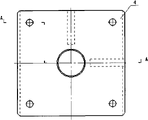
Fig. 2 is a vertical view of the present utility model, and wherein right half part removes cope match-plate pattern (22), screw (15), pin (18), die shank (16) and guide pin bushing (21);
Fig. 3-4 is respectively the main cut-open view vertical view of lower bolster (1);
Fig. 5 is the front view of guide pillar (2);
Fig. 6-7 is respectively the main cut-open view and the vertical view of die (3);
Fig. 8-9 is respectively the main cut-open view and the vertical view of lower platen (4);
Figure 10-11 is main cut-open view and the vertical view of cushion block A (5);
Figure 12-13 is main cut-open view and the vertical view of cushion block B (6);
Figure 14-15 is the main cut-open view and the vertical view of locating piece (7);
Figure 16-17 is the cut-open view and the vertical view of support (10);
Figure 18 is the front view of spring (14);
Figure 19-20 is the front view and the vertical view of die shank (16);
Figure 21-22 is the main cut-open view and the vertical view of punch (19);
Figure 23-24 is the main cut-open view and the vertical view of top board (20);
Figure 25 is the semisectional view of guide pin bushing (21);
Figure 26-27 is the main cut-open view and the vertical view of cope match-plate pattern (22).
Among Fig. 1 to Figure 27:
1. lower bolster, 2. guide pillar, 3. die, 4. lower platen, 5. cushion block A, 6. cushion block B, 7. locating piece, 8. screw, 9. straight pin, 10. locating piece support, 11. screws, 12. screws, 13. the discharging screw, 14. springs, 15. screws, 16. die shanks, 17. straight pin, 18. straight pins, 19. punch, 20. top board, 21. guide pin bushings, 22. cope match-plate patterns.
Embodiment
Among the embodiment shown in Figure 1, constant pressure-pad-force drawing experiments mould comprises shaping, location, flanging, fastening, guiding five bigger devices.Wherein, described flange fixing installation comprises each 1 of top board (20), lower platen (4), and each four on spring (14), discharging screw (13).Top board (20), lower platen (4) have the rectangular flat of circular hole for center position, and punch (19) passes the circular hole of top board (20), lower platen (4) center position; Uniform all around four stepped holes of top board (20), the correspondence position of lower platen (4) then has four manholes; Discharging screw (13) head is put into the stepped hole of top board (20), and passes lower platen (4) screw-in die (3); Spring (14) is enclosed within on the discharging screw (13), is positioned between top board (20), the lower platen (4) and is in compressive state.
This constant pressure-pad-force drawing experiments mould is mainly used on the universal testing machine.During use, circular blank is placed between lower platen (4) and the die (3), the two cover positioning systems that the position is made up of locating piece (7), locating piece support (10), screw (11 and 12) are determined, described positioning system is separately positioned on orthogonal both direction in die (3) surface level, can realize the location of different-diameter blank and guarantee bearing accuracy.Before putting into sample,, make end face to the distance at die (3) center of locating piece (7) equal the radius of sample, fix two locating pieces (7) by screw (12) then according to the position of two locating pieces of size adjustment (7) of sample.
After putting into sample and location, push down sample with lower platen (4), again spring (14), top board (20) and discharging screw (13) are placed on the lower platen (4) according to its position successively, the threaded portion of discharging screw (13) is screwed in die (3), and with the upper surface leveling of top board (20).
After more than operation is finished, 2~4 contour rectangle precompressed cushion blocks (not drawing among the figure) are placed on the upper surface of top board (20), start universal testing machine then, utilize cope match-plate pattern (22) lower surface to push down rectangle precompressed cushion block upper surface, top board (20) is compressed.Read the pressure value of universal testing machine, until equating with required pressure-pad-force estimated value, record compression height at this moment, then with the testing machine backhaul, take out rectangle precompressed cushion block, tighten discharging screw (13) and top board (20) is depressed into the compression height that is write down, the pressure-pad-force of this moment is exactly the constant value of required maintenance in drawing process.The specification of spring (14) is relevant with the size of pressure-pad-force.In the practice, can utilize experimental formula or method for numerical simulation pressure-pad-force size according to a preliminary estimate, determine the specification of spring (14) then.
When pressure-pad-force is determined, the fixing degree of depth of discharging screw (13) screw-in die (3) just, guarantee that the decrement of spring (14) and the pressure (being pressure-pad-force) that acts on the lower platen (4) are constant, and in whole drawing and forming process, keep constant, thereby satisfy the requirement of constant pressure-pad-force.At last, start universal testing machine and finish pull and stretch by the speed of testing requirements.When changing different blanks, need unclamp discharging screw (13).
This mould when satisfying Limit Drawing and requiring than test, also have simple in structure, easy to operate, Characteristics with low cost.
Claims (2)
1, a kind of drawing experiments mould of constant pressure-pad-force, comprise shaping, location, flanging, fastening, guiding five partial devices, it is characterized in that: described flange fixing installation comprises top board (20), lower platen (4) and spring (14), discharging screw (13), top board (20) and lower platen (4) have the flat board of circular hole for the center, top board (20) is evenly equipped with stepped hole all around, and lower platen (4) correspondence position has manhole; Discharging screw (13) passes top board (20), lower platen (4), and head is in top board (20) stepped hole, and threaded portion screws in die (3); Spring (14) is positioned between top board (20) and the lower platen (4), and is enclosed within outside the discharging screw (13).
2, the drawing experiments mould of a kind of constant pressure-pad-force according to claim 1, it is characterized in that: described locating device is made up of locating piece (7), screw (11 and 12) and locating piece support (10), is arranged on the interior orthogonal both direction of surface level of die (3); During drawing experiments, circular blank is placed between lower platen (4) and the die (3), finishes the location by described locating device.
Priority Applications (1)
| Application Number | Priority Date | Filing Date | Title |
|---|---|---|---|
| CN2009201278875U CN201434809Y (en) | 2009-07-02 | 2009-07-02 | Deep-drawing testing mold of constant blank holder force |
Applications Claiming Priority (1)
| Application Number | Priority Date | Filing Date | Title |
|---|---|---|---|
| CN2009201278875U CN201434809Y (en) | 2009-07-02 | 2009-07-02 | Deep-drawing testing mold of constant blank holder force |
Publications (1)
| Publication Number | Publication Date |
|---|---|
| CN201434809Y true CN201434809Y (en) | 2010-03-31 |
Family
ID=42053622
Family Applications (1)
| Application Number | Title | Priority Date | Filing Date |
|---|---|---|---|
| CN2009201278875U Expired - Fee Related CN201434809Y (en) | 2009-07-02 | 2009-07-02 | Deep-drawing testing mold of constant blank holder force |
Country Status (1)
| Country | Link |
|---|---|
| CN (1) | CN201434809Y (en) |
Cited By (11)
| Publication number | Priority date | Publication date | Assignee | Title |
|---|---|---|---|---|
| CN102554035A (en) * | 2011-12-26 | 2012-07-11 | 苏州三维精密机械有限公司 | Integral type structure of location, pressing and discharging for deep-drawing moulds |
| CN102854065A (en) * | 2011-06-29 | 2013-01-02 | 海洋王照明科技股份有限公司 | Hydrostatic pressure test machine |
| CN104858283A (en) * | 2015-05-26 | 2015-08-26 | 中南大学 | Punching device and method for automotive aluminum plate |
| CN109365639A (en) * | 2018-10-26 | 2019-02-22 | 武汉轻工大学 | Cupping tool with adjustable constant force elastic blank holding mechanism |
| CN110160888A (en) * | 2019-06-18 | 2019-08-23 | 苏州弗士达科学仪器有限公司 | A kind of flexible screen folding test device |
| CN111618155A (en) * | 2020-06-10 | 2020-09-04 | 安徽机电职业技术学院 | Deep-drawing die based on variable blank holder force control |
| CN112756464A (en) * | 2020-12-18 | 2021-05-07 | 太原理工大学 | Plate thermal drawing/bulging performance testing device based on universal testing machine |
| CN114433703A (en) * | 2021-12-15 | 2022-05-06 | 福建工程学院 | Variable pressure device and application |
| CN114733951A (en) * | 2022-03-25 | 2022-07-12 | 深圳大学 | Lower die structure and temperature-controllable edge pressing progressive forming die |
| CN114919209A (en) * | 2022-03-31 | 2022-08-19 | 歌尔股份有限公司 | Molding mechanism |
| CN114919209B (en) * | 2022-03-31 | 2024-04-26 | 歌尔股份有限公司 | Mould pressing mechanism |
-
2009
- 2009-07-02 CN CN2009201278875U patent/CN201434809Y/en not_active Expired - Fee Related
Cited By (15)
| Publication number | Priority date | Publication date | Assignee | Title |
|---|---|---|---|---|
| CN102854065A (en) * | 2011-06-29 | 2013-01-02 | 海洋王照明科技股份有限公司 | Hydrostatic pressure test machine |
| CN102854065B (en) * | 2011-06-29 | 2015-03-11 | 海洋王照明科技股份有限公司 | Hydrostatic pressure test machine |
| CN102554035A (en) * | 2011-12-26 | 2012-07-11 | 苏州三维精密机械有限公司 | Integral type structure of location, pressing and discharging for deep-drawing moulds |
| CN102554035B (en) * | 2011-12-26 | 2014-01-15 | 苏州三维精密机械有限公司 | Integral type structure of location, pressing and discharging for deep-drawing moulds |
| CN104858283A (en) * | 2015-05-26 | 2015-08-26 | 中南大学 | Punching device and method for automotive aluminum plate |
| CN109365639A (en) * | 2018-10-26 | 2019-02-22 | 武汉轻工大学 | Cupping tool with adjustable constant force elastic blank holding mechanism |
| CN110160888A (en) * | 2019-06-18 | 2019-08-23 | 苏州弗士达科学仪器有限公司 | A kind of flexible screen folding test device |
| CN110160888B (en) * | 2019-06-18 | 2022-03-29 | 苏州弗士达科学仪器有限公司 | Flexible screen folding testing device |
| CN111618155A (en) * | 2020-06-10 | 2020-09-04 | 安徽机电职业技术学院 | Deep-drawing die based on variable blank holder force control |
| CN112756464A (en) * | 2020-12-18 | 2021-05-07 | 太原理工大学 | Plate thermal drawing/bulging performance testing device based on universal testing machine |
| CN114433703A (en) * | 2021-12-15 | 2022-05-06 | 福建工程学院 | Variable pressure device and application |
| CN114733951A (en) * | 2022-03-25 | 2022-07-12 | 深圳大学 | Lower die structure and temperature-controllable edge pressing progressive forming die |
| CN114733951B (en) * | 2022-03-25 | 2024-01-23 | 深圳大学 | Lower die structure and temperature-controllable edge pressing stage progressive forming die |
| CN114919209A (en) * | 2022-03-31 | 2022-08-19 | 歌尔股份有限公司 | Molding mechanism |
| CN114919209B (en) * | 2022-03-31 | 2024-04-26 | 歌尔股份有限公司 | Mould pressing mechanism |
Similar Documents
| Publication | Publication Date | Title |
|---|---|---|
| CN201434809Y (en) | Deep-drawing testing mold of constant blank holder force | |
| CN201500733U (en) | General nitrogen spring-type mold frame | |
| CN202270830U (en) | Adjustable self-adapting type positioning and supporting device for plate material of hot stamping die | |
| CN105921604B (en) | A kind of punching plates mould and its hole-punching method | |
| CN104209406A (en) | Novel automobile beam forming process and stamping die structure | |
| CN1986102A (en) | Process and apparatus for punching hole in angle steel flange of air duct | |
| CN201385077Y (en) | Compound cold stamping die | |
| CN201855876U (en) | Die structure for compensating bending springback angle | |
| CN209139630U (en) | A kind of high-precision clinching mold | |
| CN203002952U (en) | Precision forming die group for valve pressure diaphragm | |
| CN202291147U (en) | Steel bar bending machine with adjustable curvature | |
| CN205483243U (en) | At last pneumatic testing arrangement who measures two column type weighing sensor of force standard machine | |
| CN205414097U (en) | A prefabricated hole mould for standard hole expansion test | |
| CN204108102U (en) | The piercing and flanging mould used in evaporator fin production process | |
| CN201921933U (en) | Automobile spring rocker arm multistation transfer mold | |
| CN206951935U (en) | A kind of highorder accuracy schemes hole punched device | |
| CN102189170B (en) | Notch blanking die for reel iron core clamp | |
| CN201862694U (en) | Stamping die for diaphragm spring | |
| CN201573081U (en) | Cutter adjustment structure form | |
| CN211915197U (en) | Adjusting rod adjusting wedge die | |
| CN109014122B (en) | Sheet metal die-casting die with positioning and guiding functions | |
| CN201978991U (en) | Notch blanking mold for winding iron core clamp element | |
| CN202015784U (en) | Simple die for bending machine | |
| CN207508071U (en) | A kind of groove stamping die of sheet metal | |
| CN214349147U (en) | Four-column hydraulic press |
Legal Events
| Date | Code | Title | Description |
|---|---|---|---|
| C14 | Grant of patent or utility model | ||
| GR01 | Patent grant | ||
| C17 | Cessation of patent right | ||
| CF01 | Termination of patent right due to non-payment of annual fee |
Granted publication date: 20100331 Termination date: 20100702 |