CN201422832Y - Sucking and blowing dust collector - Google Patents
Sucking and blowing dust collector Download PDFInfo
- Publication number
- CN201422832Y CN201422832Y CN2009201321752U CN200920132175U CN201422832Y CN 201422832 Y CN201422832 Y CN 201422832Y CN 2009201321752 U CN2009201321752 U CN 2009201321752U CN 200920132175 U CN200920132175 U CN 200920132175U CN 201422832 Y CN201422832 Y CN 201422832Y
- Authority
- CN
- China
- Prior art keywords
- dust collector
- collector device
- air
- blowing
- housing
- Prior art date
- Legal status (The legal status is an assumption and is not a legal conclusion. Google has not performed a legal analysis and makes no representation as to the accuracy of the status listed.)
- Expired - Fee Related
Links
Images


Landscapes
- Structures Of Non-Positive Displacement Pumps (AREA)
Abstract
The utility model discloses a sucking and blowing dust collector which comprises a housing, a sucking channel and a knob, wherein an electric motor is arranged in the housing for driving a fan; the sucking channel is formed on one side of the housing, and sucking force is generated in the sucking channel through the fan; a blowing channel is also formed on the housing, and blow force is generatedin the blowing channel through the fan; and the knob is used for controlling the air outlet of the fan to be communicated and disconnected with the blowing channel. Because the sucking and blowing dust collector provided by the utility model adopts the air outlet of the prior dust collector for constraint and blows air out of the opening of the blowing channel, the fan driven by the electric motorof the dust collector is fully utilized to realize the sucking channel and the blow channel at the same time, so that the function setup of the blowing operation on the dust collector is realized andthe function of the dust collector is increased.
Description
Technical field
The utility model relates to a kind of dust collector device, in particular a kind of improvement of pressure-vaccum wind structure of dust catcher.
Background technology
In the prior art, dust catcher is the instrument of using always of keeping a public place clean, its common setting is the fan that an electrical motor driven is set in a housing, form the negative pressure of strong suction by the rotation of fan blade, the opening that utilizes an air-suction channel extend to be provided with forward on housing can for example dust or paper scrap etc. suck air-suction channel with foul; There is a filter bag to be used to filter and install the foul of suction in the rear end of air-suction channel operated by rotary motion, can realizes sweeping the simple operations of health thus.
But because fouls such as dust in the environment and paper scrap may exist in place, in the slit or corner, the dust catcher of prior art just is difficult to realize cleaning up by suction merely; In addition, present dust catcher only has the function of air draught, blows the operation of power for needs, for example gives the inflation of ball or water wing, is helpless.
Therefore, prior art has yet to be improved and developed.
The utility model content
But the purpose of this utility model is to provide a kind of dust collector device of pressure-vaccum wind, at the defective of above-mentioned prior art, provides a kind of dust collector device that air draught and two kinds of operations of blowing can be provided simultaneously.
The technical solution of the utility model is as follows:
But a kind of dust collector device of pressure-vaccum wind, it comprises a housing, is provided with an electro-motor in described housing, is used to drive a fan; And an air-suction channel, be arranged on described housing one side, produce suction therein by described fan; Wherein, on described housing, also be provided with a blowing passage, produce the power of blowing therein by described fan; And a knob, be used to control air outlet and the described blowing channel connection or the disconnection of described fan.
Described dust collector device, wherein, described blowing passage and described air-suction channel are parallel to be provided with, and at described housing with the side opening setting.
Described dust collector device, wherein, described housing is provided with the other ease of an air-out mouthful, and the plate of becalming is set, and is controlled at conversion connection between other ease of described air-out mouthful and the described blowing passage by described knob.
Described dust collector device, wherein, the described plate of becalming is arranged on the motor sub-assembly, described motor sub-assembly comprises that one is located at the cover body of described fan air side, and described cover body is provided with the blowhole with described blowing channel connection, the described plate of becalming is arranged on the described cover body by a pivot, is used for the controlled described blowhole of blocking.
Described dust collector device wherein, also is provided with an interface arrangement, is respectively applied for the opening of peg graft described air-suction channel and described blowing passage.
Described dust collector device, wherein, described interface arrangement comprises that at least one first connects mouth, the opening of the described blowing passage that is used to peg graft; And one first blow gun, be used for to the water wing gas injection.
Described dust collector device, wherein, described interface arrangement comprises that at least one second connects mouth, the opening of the described air-suction channel that is used to peg graft; And one second suction nozzle, be used for bleeding from water wing.
Described dust collector device wherein, also is provided with a blower, is used to connect the opening of described blowing passage, and extends to opening the place ahead setting of described air-suction channel.
Described dust collector device, wherein, described housing setting comprises a left shell and a right shell body, fastening forms.
Described dust collector device wherein, is provided with a dc-battery box in described housing, be used to assemble the battery that drives described electro-motor.
But the dust collector device of a kind of pressure-vaccum wind provided by the utility model, because having adopted the air outlet that will have dust collector device now to retrain also can blow out by the opening of blowing passage, thereby made full use of the fan that the dust catcher electro-motor is driven, can realize air-suction channel and blowing passage simultaneously, thereby on dust catcher, realized the function setting of blowing and operating, the function that has expanded dust catcher; Simultaneously, the blowing passage has also made things convenient for the function that foul is blown out from the position that is difficult to sucking-off to realize.
Description of drawings
But Fig. 1 is the schematic perspective view of the dust collector device of the utility model pressure-vaccum wind;
But Fig. 2 is the decomposition texture schematic diagram of the dust collector device of the utility model pressure-vaccum wind;
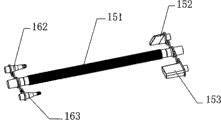
Fig. 3 is the interface arrangement embodiment schematic diagram of the utility model dust catcher;
Fig. 4 a is the partial cutaway schematic of the utility model dust collector device when the pressure-vaccum character and conduct is done;
Fig. 4 b is the partial cutaway schematic of the utility model dust collector device when only air draught is operated;
Fig. 5 a is the schematic perspective view of motor sub-assembly among one of embodiment of the utility model dust collector device;
Fig. 5 b is the decomposition texture schematic diagram of motor sub-assembly shown in Fig. 5 a;
Fig. 5 c is the generalized section of motor sub-assembly shown in Fig. 5 a;
Fig. 6 a is the schematic diagram of assembling blower in another preferred embodiment of the utility model dust collector device;
Fig. 6 b is the schematic diagram that the assembling interface arrangement carries out the water wing charge operation in another preferred embodiment of the utility model dust collector device;
Fig. 6 c is that the assembling interface arrangement carries out the bleed schematic diagram of operation of water wing in another preferred embodiment of the utility model dust collector device.
The specific embodiment
Below preferred embodiment of the present utility model is described in detail.
The utility model dust collector device is a kind of dust collector device that can carry out suction operation simultaneously, be characterized in utilizing electro-motor, drive the rotation of the lid of becalming by knob, change the air channel, change the position of air outlet, connection blowing passage is changed into from the other ease mouth of air-out in the air-out air channel of dust catcher in the prior art, thereby reach two kinds of difference in functionalitys of controllable realization blowing and air draught.The utility model has increased the function of blowing on the basis of common dust catcher, after producing by boasting the dust in the corner, blot clean again; And can realize realization to the air blowing function, and for example balloon or ball inflation are needed, the inflation of water wing is needed or the like.
But the dust collector device 100 of pressure-vaccum wind described in the utility model, as shown in Figure 1, it comprises a housing 110, switch 111 and knob 112 can be set on this housing 110, the former is common as prior art institute, be used for controlling the switch of dust catcher circuit, for example whether the work of described electro-motor; Described knob 112 is used to drive the air channel conversion in the described housing 110, thereby can realize the air channel is converted to the blowing passage from the other ease mouth of the air-out of prior art, as shown in Figure 1, what can see on described housing 110 is the opening of described air-suction channel, it is air intake vent 121, with the opening of the parallel described blowing passage that is provided with of homonymy, promptly air outlet 122.
As shown in Figure 2, in the dust collector device described in the utility model, described housing 110 has comprised a left shell 113 and a right shell body 114, and both can snap together, and install the space that installs of circuit and electro-motor and fan with formation.Described electro-motor 131 forms with motor sub-assembly 130 together with described fan 132, shown in Fig. 2 and Fig. 5 a, Fig. 5 b and Fig. 5 c, can be assemblied in the described housing 110, described housing 110 front ends are provided with one and form air-suction channel and the procapsid 115 of the passage of drying, as shown in Figure 2, and in described housing 110, can also be provided with a dc-battery box 141, be used to assemble the battery that drives described electro-motor, so that realize the portable use of dust collector device described in the utility model.
Shown in Fig. 5 a, Fig. 5 b and Fig. 5 c, in the dust collector device described in the utility model, described electro-motor can be arranged in the motor sub-assembly 130, described electro-motor 131 drives and connects a fan 132, shown in Fig. 5 c, be provided with a cover body 133 in the air side of described electro-motor 131, and in this cover body 133, be provided with the plate 134 of becalming, be articulated on this cover body 133, can by described knob 112 adjust be controlled at the other ease of air-out mouthfuls 135 and and the blowhole 136 connected of described blowing passage between switch.
In the dust collector device 100 described in the utility model, also be provided with an interface arrangement 150, in the preferred embodiment as shown in Figure 3, can be set to a general pipe 151, and be respectively arranged with several the mouth that connects in two side ends, the opening 121,122 of be used to peg graft described air-suction channel and described blowing passage.As shown in Figure 3, can be provided with one first and connect mouth 152, the opening 122 of the blowing passage that is used for pegging graft, simultaneously, first blow gun 162 is set, is used for the various excuses that adaptive air blowing needs at the other end of described general pipe 151, the inflatable mouth of water wing 200 for example is shown in Fig. 6 b.
In addition, also can select or be provided with one second simultaneously to connect mouth 153, the opening 121 of described air-suction channel is used for pegging graft, shown in Fig. 3 and Fig. 6 c, the other end of described general pipe 151 then correspondence one second suction nozzle 163 is set, be used for adaptive various air-breathing needs, for example the inflatable mouth of water wing 200 is used for water wing is exitted.
In the dust collector device described in the utility model, on the described interface arrangement 150 can with described first connect mouth 152, second connect mouth 153 with first blow gun 162, second suction nozzle 163 is arranged to respectively has flexible cord to be connected with described general pipe, to prevent respectively to connect losing of mouth.
In the dust collector device described in the utility model, one blower 161 can also be set, be used for the opening 122 of adaptive described blowing passage, shown in Fig. 6 a, like this, when using dust collector device described in the utility model, the blower of described dust collector device can be reached in the corner or slit that is difficult to reach, after foul blown out again the opening by described air-suction channel 121 foul is sucked dust catcher, guaranteed operating efficiency and convenient handy.
Operation principle of the present utility model, shown in Fig. 4 a and Fig. 4 b, be two groundwork states of the utility model dust collector device.
Shown in Fig. 4 a, when knob being screwed to pressure-vaccum operation simultaneously, air-suction channel 171 is worked as the dust catcher of prior art, under the driving of electro-motor 131, the air that fan 132 drives in the described air-suction channel 171 forms powerful negative-pressure sucking, foul can be sucked cavity 181, and intercept in this cavity 181 by the filtration of filter course 182.When air-flow enters in the described motor sub-assembly, because knob is opened described blowhole 136 with the described plate 134 of becalming, close the other ease mouthful (not shown) of described air-out simultaneously, thus, air-flow enters in the described blowing passage 172, and blows out from described air outlet 122.Under optional state, described blower 161 can be assembled, shown in Fig. 6 a on described air outlet 122.
Shown in Fig. 4 b, when knob described in the utility model is screwed to when the air draught function only is provided, the plate 134 of becalming in described motor sub-assembly is closed described blowhole 136, open the other ease mouth 135 of described air-out simultaneously, at this moment, the operation principle of dust collector device described in the utility model is same as the prior art, does not repeat them here.
Dust collector device described in the utility model by the control of described becalm plate and knob is set, has realized carrying out simultaneously the possibility of air draught and blowing operation on dust catcher, expanded the function of dust catcher.Can be in the utility model dust collector device from dust catcher front end blow gas, make the dust at cleaning dead angle can obtain cleaning, make the dust catcher can better sanitation and hygiene; Simultaneously, can realize inflation, venting function to other equipment that need blow such as water wing, for user's outdoor activity provides more convenience, can portable realization the gas that charges and discharge of water wing, inflatable packer, pneumatic boat etc. be operated with the utility model dust collector device.
Should be understood that, for those of ordinary skills, can be improved according to the above description or conversion, and all these improvement and conversion all should belong to the protection domain of the utility model claims.
Claims (10)
- But 1, a kind of dust collector device of pressure-vaccum wind, it comprises a housing, is provided with an electro-motor in described housing, is used to drive a fan; And an air-suction channel, be arranged on described housing one side, produce suction therein by described fan; It is characterized in that, on described housing, also be provided with a blowing passage, produce the power of blowing therein by described fan; And a knob, be used to control air outlet and the described blowing channel connection or the disconnection of described fan.
- 2, dust collector device according to claim 1 is characterized in that, described blowing passage and described air-suction channel are parallel to be provided with, and at described housing with the side opening setting.
- 3, dust collector device according to claim 2 is characterized in that, described housing is provided with the other ease of an air-out mouthful, and the plate of becalming is set, and is controlled at conversion connection between other ease of described air-out mouthful and the described blowing passage by described knob.
- 4, dust collector device according to claim 3, it is characterized in that, the described plate of becalming is arranged on the motor sub-assembly, described motor sub-assembly comprises that one is located at the cover body of described fan air side, and described cover body is provided with the blowhole with described blowing channel connection, the described plate of becalming is arranged on the described cover body by a pivot, is used for the controlled described blowhole of blocking.
- 5, dust collector device according to claim 2 is characterized in that, also is provided with an interface arrangement, is respectively applied for the opening of peg graft described air-suction channel and described blowing passage.
- 6, dust collector device according to claim 5 is characterized in that, described interface arrangement comprises that at least one first connects mouth, the opening of the described blowing passage that is used to peg graft; And one first blow gun, be used for to the water wing gas injection.
- 7, dust collector device according to claim 5 is characterized in that, described interface arrangement comprises that at least one second connects mouth, the opening of the described air-suction channel that is used to peg graft; And one second suction nozzle, be used for bleeding from water wing.
- 8, dust collector device according to claim 2 is characterized in that, also is provided with a blower, is used to connect the opening of described blowing passage, and extends to opening the place ahead setting of described air-suction channel.
- 9, dust collector device according to claim 1 is characterized in that, described housing setting comprises a left shell and a right shell body, and fastening forms.
- 10, dust collector device according to claim 1 is characterized in that, is provided with a dc-battery box in described housing, is used to assemble the battery that drives described electro-motor.
Priority Applications (1)
| Application Number | Priority Date | Filing Date | Title |
|---|---|---|---|
| CN2009201321752U CN201422832Y (en) | 2009-05-22 | 2009-05-22 | Sucking and blowing dust collector |
Applications Claiming Priority (1)
| Application Number | Priority Date | Filing Date | Title |
|---|---|---|---|
| CN2009201321752U CN201422832Y (en) | 2009-05-22 | 2009-05-22 | Sucking and blowing dust collector |
Publications (1)
| Publication Number | Publication Date |
|---|---|
| CN201422832Y true CN201422832Y (en) | 2010-03-17 |
Family
ID=42022260
Family Applications (1)
| Application Number | Title | Priority Date | Filing Date |
|---|---|---|---|
| CN2009201321752U Expired - Fee Related CN201422832Y (en) | 2009-05-22 | 2009-05-22 | Sucking and blowing dust collector |
Country Status (1)
| Country | Link |
|---|---|
| CN (1) | CN201422832Y (en) |
Cited By (22)
| Publication number | Priority date | Publication date | Assignee | Title |
|---|---|---|---|---|
| CN103315678A (en) * | 2012-03-20 | 2013-09-25 | 田永茂 | Dust collecting and air blowing integrated dust remover |
| CN103315680A (en) * | 2012-03-20 | 2013-09-25 | 田永茂 | Air-blowing dust collector |
| CN104367265A (en) * | 2013-08-13 | 2015-02-25 | 苏州宝时得电动工具有限公司 | Blower-vacuum |
| CN106073629A (en) * | 2016-01-20 | 2016-11-09 | 江苏美的清洁电器股份有限公司 | Hand held cleaner |
| CN104367265B (en) * | 2013-08-13 | 2016-11-30 | 苏州宝时得电动工具有限公司 | Blower |
| US20170202414A1 (en) * | 2016-01-20 | 2017-07-20 | Jiangsu Midea Cleaning Appliances Co., Ltd. | Cleaner |
| WO2017124629A1 (en) * | 2016-01-20 | 2017-07-27 | 江苏美的清洁电器股份有限公司 | Hand-held vacuum cleaner |
| WO2017124627A1 (en) * | 2016-01-20 | 2017-07-27 | 江苏美的清洁电器股份有限公司 | Vacuum cleaner |
| CN107080491A (en) * | 2017-06-01 | 2017-08-22 | 云南电网有限责任公司信息中心 | A kind of electrical maintenance handhold dust exhaust apparatus |
| CN107468149A (en) * | 2017-10-13 | 2017-12-15 | 镇江江润电气设备有限公司 | A kind of wiring board dust catcher |
| JP2018015412A (en) * | 2016-07-29 | 2018-02-01 | 東芝ライフスタイル株式会社 | Vacuum cleaner |
| JP2018015410A (en) * | 2016-07-29 | 2018-02-01 | 東芝ライフスタイル株式会社 | Vacuum cleaner |
| JP2018108229A (en) * | 2016-12-29 | 2018-07-12 | 三菱電機株式会社 | Cleaner |
| CN108697284A (en) * | 2016-07-29 | 2018-10-23 | 东芝生活电器株式会社 | Electric dust collector |
| US20180310786A1 (en) * | 2016-01-20 | 2018-11-01 | Jiangsu Midea Cleaning Appliances Co., Ltd. | Hand-held vacuum cleaner |
| CN108888176A (en) * | 2018-08-22 | 2018-11-27 | 珠海格力电器股份有限公司 | Dust collecting equipment |
| JP2019187958A (en) * | 2018-04-27 | 2019-10-31 | 三菱電機株式会社 | Cleaner and support device |
| US20200046181A1 (en) * | 2018-08-13 | 2020-02-13 | Hall Labs Llc | Vacuum and blower |
| JP2020178884A (en) * | 2019-04-25 | 2020-11-05 | 三菱電機株式会社 | Vacuum cleaner |
| CN112205914A (en) * | 2019-07-09 | 2021-01-12 | 东芝生活电器株式会社 | Blower accessory and electric dust collector |
| CN113842081A (en) * | 2021-09-23 | 2021-12-28 | 台山市冠鑫机械有限公司 | Dust collector and control method |
| WO2024022250A1 (en) * | 2022-07-29 | 2024-02-01 | 苏州市伟克斯电器有限公司 | Pet care machine and pet hair care method |
-
2009
- 2009-05-22 CN CN2009201321752U patent/CN201422832Y/en not_active Expired - Fee Related
Cited By (36)
| Publication number | Priority date | Publication date | Assignee | Title |
|---|---|---|---|---|
| CN103315680B (en) * | 2012-03-20 | 2016-12-07 | 田永茂 | The vacuum cleaner of band blowing |
| CN103315680A (en) * | 2012-03-20 | 2013-09-25 | 田永茂 | Air-blowing dust collector |
| CN103315678A (en) * | 2012-03-20 | 2013-09-25 | 田永茂 | Dust collecting and air blowing integrated dust remover |
| CN103315678B (en) * | 2012-03-20 | 2016-12-07 | 田永茂 | Dust suction, blowing integrated dust remover |
| CN104367265A (en) * | 2013-08-13 | 2015-02-25 | 苏州宝时得电动工具有限公司 | Blower-vacuum |
| CN104367265B (en) * | 2013-08-13 | 2016-11-30 | 苏州宝时得电动工具有限公司 | Blower |
| US20180310786A1 (en) * | 2016-01-20 | 2018-11-01 | Jiangsu Midea Cleaning Appliances Co., Ltd. | Hand-held vacuum cleaner |
| CN106073629A (en) * | 2016-01-20 | 2016-11-09 | 江苏美的清洁电器股份有限公司 | Hand held cleaner |
| WO2017124629A1 (en) * | 2016-01-20 | 2017-07-27 | 江苏美的清洁电器股份有限公司 | Hand-held vacuum cleaner |
| WO2017124627A1 (en) * | 2016-01-20 | 2017-07-27 | 江苏美的清洁电器股份有限公司 | Vacuum cleaner |
| WO2017124633A1 (en) * | 2016-01-20 | 2017-07-27 | 江苏美的清洁电器股份有限公司 | Vacuum cleaner |
| US10624509B2 (en) | 2016-01-20 | 2020-04-21 | Jiangsu Midea Cleaning Appliances Co., Ltd. | Vacuum cleaner |
| US10575688B2 (en) * | 2016-01-20 | 2020-03-03 | Jiangsu Midea Cleaning Appliances Co., Ltd. | Hand-held vacuum cleaner |
| US10531773B2 (en) * | 2016-01-20 | 2020-01-14 | Jiangsu Midea Cleaning Appliances Co., Ltd. | Hand-held vacuum cleaner |
| US20170202414A1 (en) * | 2016-01-20 | 2017-07-20 | Jiangsu Midea Cleaning Appliances Co., Ltd. | Cleaner |
| US20180042436A1 (en) * | 2016-01-20 | 2018-02-15 | Jiangsu Midea Cleaning Appliances Co., Ltd. | Hand-held vacuum cleaner |
| CN106073629B (en) * | 2016-01-20 | 2019-05-10 | 江苏美的清洁电器股份有限公司 | Hand held cleaner |
| US10201259B2 (en) * | 2016-01-20 | 2019-02-12 | Jiangsu Midea Cleaning Appliances Co., Ltd. | Cleaner |
| JP2018015410A (en) * | 2016-07-29 | 2018-02-01 | 東芝ライフスタイル株式会社 | Vacuum cleaner |
| CN108697284A (en) * | 2016-07-29 | 2018-10-23 | 东芝生活电器株式会社 | Electric dust collector |
| JP2018015412A (en) * | 2016-07-29 | 2018-02-01 | 東芝ライフスタイル株式会社 | Vacuum cleaner |
| JP2018108229A (en) * | 2016-12-29 | 2018-07-12 | 三菱電機株式会社 | Cleaner |
| CN107080491A (en) * | 2017-06-01 | 2017-08-22 | 云南电网有限责任公司信息中心 | A kind of electrical maintenance handhold dust exhaust apparatus |
| CN107468149A (en) * | 2017-10-13 | 2017-12-15 | 镇江江润电气设备有限公司 | A kind of wiring board dust catcher |
| JP2022183353A (en) * | 2018-04-27 | 2022-12-08 | 三菱電機株式会社 | Cleaner system |
| JP2019187958A (en) * | 2018-04-27 | 2019-10-31 | 三菱電機株式会社 | Cleaner and support device |
| JP7409463B2 (en) | 2018-04-27 | 2024-01-09 | 三菱電機株式会社 | vacuum cleaner system |
| US20200046181A1 (en) * | 2018-08-13 | 2020-02-13 | Hall Labs Llc | Vacuum and blower |
| US10806312B2 (en) * | 2018-08-13 | 2020-10-20 | Hall Labs Llc | Vacuum and blower |
| CN108888176A (en) * | 2018-08-22 | 2018-11-27 | 珠海格力电器股份有限公司 | Dust collecting equipment |
| CN108888176B (en) * | 2018-08-22 | 2023-11-21 | 珠海格力电器股份有限公司 | Dust collection equipment |
| JP2020178884A (en) * | 2019-04-25 | 2020-11-05 | 三菱電機株式会社 | Vacuum cleaner |
| JP7230670B2 (en) | 2019-04-25 | 2023-03-01 | 三菱電機株式会社 | vacuum cleaner |
| CN112205914A (en) * | 2019-07-09 | 2021-01-12 | 东芝生活电器株式会社 | Blower accessory and electric dust collector |
| CN113842081A (en) * | 2021-09-23 | 2021-12-28 | 台山市冠鑫机械有限公司 | Dust collector and control method |
| WO2024022250A1 (en) * | 2022-07-29 | 2024-02-01 | 苏州市伟克斯电器有限公司 | Pet care machine and pet hair care method |
Similar Documents
| Publication | Publication Date | Title |
|---|---|---|
| CN201422832Y (en) | Sucking and blowing dust collector | |
| CN101205708B (en) | Blowing and sucking machine | |
| CN103321171B (en) | Blower | |
| CN105586846B (en) | Blower | |
| WO2024022250A1 (en) | Pet care machine and pet hair care method | |
| CN104631370B (en) | Suction and blowing device and the method using the suction and blowing device | |
| CN200981987Y (en) | Blowing and sucking machine | |
| CN202851398U (en) | Blower with blowing and sucking functions | |
| CN200996139Y (en) | Pressure-vacuum sucker | |
| CN105212514B (en) | Circuit board cleaning brush | |
| CN201516005U (en) | Blowing/suction machine | |
| CN209059039U (en) | Cleaning vacuum plant | |
| CN207995349U (en) | A kind of sound equipment being convenient to clean dust | |
| CN209899257U (en) | Dust collector capable of switching air blowing | |
| CN207693511U (en) | A kind of hand held cleaner | |
| CN206101395U (en) | Little miniature insect collecting ware of pen type | |
| CN220967203U (en) | Portable vehicle-mounted suction and blowing integrated machine | |
| CN215621884U (en) | Automotive interior clean-up equipment | |
| CN110403520A (en) | One kind holding vertical wireless mute dust collector | |
| CN219998873U (en) | Energy-saving environment-friendly low-voltage cabinet device | |
| CN218304703U (en) | Multifunctional portable handheld wireless dust collector | |
| CN219812869U (en) | Equipment integrating blowing and air suction | |
| CN221683238U (en) | High-speed wireless handheld violent fan | |
| CN212184812U (en) | Mosquito-killing and cooling dual-purpose fan | |
| CN218415390U (en) | Power distribution cabinet with dehumidification device |
Legal Events
| Date | Code | Title | Description |
|---|---|---|---|
| C14 | Grant of patent or utility model | ||
| GR01 | Patent grant | ||
| CF01 | Termination of patent right due to non-payment of annual fee |
Granted publication date: 20100317 Termination date: 20180522 |
|
| CF01 | Termination of patent right due to non-payment of annual fee |