CN201419451Y - Die core pulling mechanism - Google Patents
Die core pulling mechanism Download PDFInfo
- Publication number
- CN201419451Y CN201419451Y CN2009200727010U CN200920072701U CN201419451Y CN 201419451 Y CN201419451 Y CN 201419451Y CN 2009200727010 U CN2009200727010 U CN 2009200727010U CN 200920072701 U CN200920072701 U CN 200920072701U CN 201419451 Y CN201419451 Y CN 201419451Y
- Authority
- CN
- China
- Prior art keywords
- slide block
- product
- backing plate
- fixed
- pulling mechanism
- Prior art date
- Legal status (The legal status is an assumption and is not a legal conclusion. Google has not performed a legal analysis and makes no representation as to the accuracy of the status listed.)
- Expired - Fee Related
Links
Images

Abstract
The utility model provides a die core pulling mechanism which comprises an oil groove backing plate, a slide block arranged on the oil groove backing plate, a product arranged on one side of the slideblock, an angular cam arranged in the middle of the slide block, a back locking device arranged on the other side of the slide block, and an oblique wedge arranged between the slide block and the back locking device and fixed with the angular cam on the cover die. The die core pulling mechanism is characterized in that a groove is arranged on the slide block, one end of the push pin of the slideblock is arranged in the groove and meshed with a push pin fixing block, and the other end of the push pin of the slide block is tightly propped against the push pin fixing block of the product and fixed on the oil groove backing plate. The die core pulling mechanism has the advantages that the slide block push pin is fixed in the ejector die through the push pin fixing block and can not move along with the slide block, thereby pushing the product during the core pulling process through the slide block and enabling the product not to be deformed due to the clamping force of the slide block.
Description
Technical field
The utility model provides a kind of Mold Core-pulling Mechanism, is used for product greatlyyer at the Slipper package power, draws the mould of distortion easily, belongs to the injection molding technology field.
Background technology
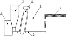
The plastic product of some injection mouldings, because the structural limitations of product, product is bigger than hinge at the Slipper package power of mould, loose core for general slide block and easily product to be drawn distortion, as shown in Figure 1, for traditional mould slide block schematic diagram of loosing core, by product 1, slide block 2, tiltedly carve 3, anti-lock device 4, oil groove backing plate 5 and tiltedly lead and lean on 8 compositions, wherein tiltedly carve 3 and tiltedly lead and lean on 8 and be fixed on the mould cover half, remaining parts is all stayed the dynamic model part.Angle Pin 8 drive slide blocks 2 slide on oil groove backing plate 5 during mould die sinking campaign, thereby make slide block break away from product, and product just can eject safely like this.But because the moulding of product side is many, package power is bigger, pulls product when slide block is loosed core easily, causes scrappage to increase, and influence is produced.
Summary of the invention
The purpose of this utility model provides a kind of product that is difficult for pulling, thereby improves the Mold Core-pulling Mechanism that product percent of pass can make the mould ordinary production.
In order to achieve the above object, the technical solution of the utility model provides a kind of Mold Core-pulling Mechanism, comprise the oil groove backing plate, the oil groove backing plate is provided with slide block, slide block one side is provided with product, the slide block middle part is provided with Angle Pin, the slide block opposite side is provided with anti-lock device, be provided with tiltedly between slide block and the anti-lock device and carve, tiltedly carve with Angle Pin and be fixed on the mould cover half, it is characterized in that, described slide block is provided with groove, one end of slide block thimble is located in the groove and with the thimble fixed block and is meshed, and the other end of slide block thimble is near product, and the thimble fixed block is fixed on the oil groove backing plate.
The utility model has the advantages that described slide block thimble is to be fixed among the dynamic model and can not move with slide block with the thimble fixed block.Can withstand product in the process that slide block is loosed core makes product can not produce distortion because of the package power of slide block.
Description of drawings
Fig. 1 is traditional mould slide block schematic diagram of loosing core;
Fig. 2 is a Mold Core-pulling Mechanism schematic diagram of the present utility model.
The specific embodiment
Further specify the utility model below in conjunction with embodiment.
Embodiment
As shown in Figure 2, be Mold Core-pulling Mechanism schematic diagram of the present utility model, described Mold Core-pulling Mechanism tiltedly carves 3 by slide block 2, and anti-lock device 4, oil groove backing plate 5, slide block thimble 6, thimble fixed block 7 and tiltedly leading are leant on 8 and formed.Wherein, tiltedly carve 3 and tiltedly lead and lean on 8 and be fixed on the mould cover half, remaining parts is all stayed the dynamic model part.
Oil groove backing plate 5 is provided with slide block 2, slide block 2 one sides are provided with product 1, slide block 2 middle parts are provided with Angle Pin 8, slide block 2 opposite sides are provided with anti-lock device 4, are provided with between slide block 2 and the anti-lock device 4 and tiltedly carve 3, tiltedly carve 3 and Angle Pin 8 be fixed on the mould cover half, it is characterized in that, described slide block 2 is provided with groove 10, and an end of slide block thimble 6 is located in the groove 10 and with thimble fixed block 7 and is meshed, and the other end of slide block thimble 6 is fixed on the oil groove backing plate 5 near product 1 thimble fixed block 7.
Angle Pin 8 drive slide blocks 2 slide on oil groove backing plate 5 during mould die sinking campaign, because the slide block thimble 6 of slide block inside is fixed on the template in company with thimble fixed block 7 together, therefore can not move together in company with slide block 2, so this thimble 6 can withstand product 1 all the time, thereby make product can not produce distortion because of the package power of slide block.
By using this novel Mold Core-pulling Mechanism can effectively avoid product in knockout course, to be out of shape because of the caused product of the package power of loosing core, effectively raise the qualification rate of product, reduced production cost, guaranteed the ordinary production of mould.
Claims (1)
1, a kind of Mold Core-pulling Mechanism, comprise oil groove backing plate (5), oil groove backing plate (5) is provided with slide block (2), slide block (2) one sides are provided with product (1), slide block (2) middle part is provided with Angle Pin (8), slide block (2) opposite side is provided with anti-lock device (4), be provided with tiltedly between slide block (2) and the anti-lock device (4) and carve (3), tiltedly carving (3) and Angle Pin (8) is fixed on the mould cover half, it is characterized in that described slide block (2) is provided with groove (10), an end of slide block thimble (6) is located in the groove (10) and with thimble fixed block (7) and is meshed, the other end of slide block thimble (6) is near product (1), and thimble fixed block (7) is fixed on the oil groove backing plate (5).
Priority Applications (1)
| Application Number | Priority Date | Filing Date | Title |
|---|---|---|---|
| CN2009200727010U CN201419451Y (en) | 2009-05-21 | 2009-05-21 | Die core pulling mechanism |
Applications Claiming Priority (1)
| Application Number | Priority Date | Filing Date | Title |
|---|---|---|---|
| CN2009200727010U CN201419451Y (en) | 2009-05-21 | 2009-05-21 | Die core pulling mechanism |
Publications (1)
| Publication Number | Publication Date |
|---|---|
| CN201419451Y true CN201419451Y (en) | 2010-03-10 |
Family
ID=41806100
Family Applications (1)
| Application Number | Title | Priority Date | Filing Date |
|---|---|---|---|
| CN2009200727010U Expired - Fee Related CN201419451Y (en) | 2009-05-21 | 2009-05-21 | Die core pulling mechanism |
Country Status (1)
| Country | Link |
|---|---|
| CN (1) | CN201419451Y (en) |
Cited By (7)
| Publication number | Priority date | Publication date | Assignee | Title |
|---|---|---|---|---|
| CN102114678A (en) * | 2011-01-23 | 2011-07-06 | 杭州电子科技大学 | Device provided with stepping core-pulling mechanism with nested double slide blocks |
| CN102275262A (en) * | 2011-05-11 | 2011-12-14 | 延锋伟世通汽车模具有限公司 | Integrated structure composed of loose core and inclined roof |
| CN102514152A (en) * | 2011-12-03 | 2012-06-27 | 江苏云意电气股份有限公司 | Core-pulling sliding block mechanism of injection mould |
| CN102672913A (en) * | 2012-05-10 | 2012-09-19 | 浙江凯华模具有限公司 | Inclined guide pillar slide block type secondary demolding mechanism of injection mold |
| CN102744814A (en) * | 2012-07-24 | 2012-10-24 | 泰德兴精密电子(昆山)有限公司 | Anti-collision device for slide block |
| CN102848531A (en) * | 2012-09-21 | 2013-01-02 | 东泰精密模具(苏州)有限公司 | Secondary angle core-pulling die with nitrogen spring |
| CN110154327A (en) * | 2019-06-25 | 2019-08-23 | 浙江台州美多模具有限公司 | The dark pumping core-pulling mechanism of injection mold |
-
2009
- 2009-05-21 CN CN2009200727010U patent/CN201419451Y/en not_active Expired - Fee Related
Cited By (10)
| Publication number | Priority date | Publication date | Assignee | Title |
|---|---|---|---|---|
| CN102114678A (en) * | 2011-01-23 | 2011-07-06 | 杭州电子科技大学 | Device provided with stepping core-pulling mechanism with nested double slide blocks |
| CN102114678B (en) * | 2011-01-23 | 2013-01-02 | 杭州电子科技大学 | Device provided with stepping core-pulling mechanism with nested double slide blocks |
| CN102275262A (en) * | 2011-05-11 | 2011-12-14 | 延锋伟世通汽车模具有限公司 | Integrated structure composed of loose core and inclined roof |
| CN102514152A (en) * | 2011-12-03 | 2012-06-27 | 江苏云意电气股份有限公司 | Core-pulling sliding block mechanism of injection mould |
| CN102672913A (en) * | 2012-05-10 | 2012-09-19 | 浙江凯华模具有限公司 | Inclined guide pillar slide block type secondary demolding mechanism of injection mold |
| CN102672913B (en) * | 2012-05-10 | 2014-06-11 | 浙江凯华模具有限公司 | Inclined guide pillar slide block type secondary demolding mechanism of injection mold |
| CN102744814A (en) * | 2012-07-24 | 2012-10-24 | 泰德兴精密电子(昆山)有限公司 | Anti-collision device for slide block |
| CN102848531A (en) * | 2012-09-21 | 2013-01-02 | 东泰精密模具(苏州)有限公司 | Secondary angle core-pulling die with nitrogen spring |
| CN110154327A (en) * | 2019-06-25 | 2019-08-23 | 浙江台州美多模具有限公司 | The dark pumping core-pulling mechanism of injection mold |
| CN110154327B (en) * | 2019-06-25 | 2021-12-14 | 浙江台州美多模具有限公司 | Blind core-pulling mechanism of injection mold |
Similar Documents
| Publication | Publication Date | Title |
|---|---|---|
| CN201419451Y (en) | Die core pulling mechanism | |
| CN102950686A (en) | Inclined roof device of plastic mold | |
| CN203957277U (en) | The mould of dynamic model, the two-way release of cover half | |
| CN202062561U (en) | Sliding block core pulling mechanism capable of realizing auxiliary pressing for product | |
| CN203293487U (en) | Flexible pipe plug injection mold | |
| CN204054517U (en) | A kind of practical large-angle inclined to ejecting pulled core structure | |
| CN103538211B (en) | Die sinking both direction core-pulling mechanism | |
| CN202727249U (en) | Plastic mold | |
| CN204736407U (en) | Prevent mould of product deformation | |
| CN103909626A (en) | Inner core-pulling device of injection mold | |
| CN104985758A (en) | Injection mold capable of preventing product from being damaged under pulling | |
| CN202952490U (en) | Angle pin fixing mechanism | |
| CN202016179U (en) | Ejection mechanism with inclined guide pillar and outer slide block for improved injection mould | |
| CN202200477U (en) | Sliding core-pulling mechanism in inclined guide column at side hole of plastic shell | |
| CN201800201U (en) | Mould realizing forced demoulding | |
| CN202029332U (en) | External bracing demoulding mechanism of automobile bumper injection mould | |
| CN201998398U (en) | Angle ejection structure for injection mould | |
| CN203726741U (en) | Core-pulling forced-demolding mechanism of fast joint pipe mold | |
| CN202480278U (en) | Plastic mould slide thimble device | |
| CN205767317U (en) | A kind of injection mold | |
| CN201950783U (en) | Line thimble structure for injection mold | |
| CN201544409U (en) | Injection mould for toilet lid | |
| CN203542970U (en) | Slider first-back type injection mould | |
| CN204894377U (en) | Can prevent to pull injection mold of product | |
| CN202088411U (en) | Mold stripping mechanism |
Legal Events
| Date | Code | Title | Description |
|---|---|---|---|
| C14 | Grant of patent or utility model | ||
| GR01 | Patent grant | ||
| CF01 | Termination of patent right due to non-payment of annual fee |
Granted publication date: 20100310 Termination date: 20160521 |
|
| CF01 | Termination of patent right due to non-payment of annual fee |